Warehouse 3D Scanning in Warnervale: Designing Around What Is Actually There

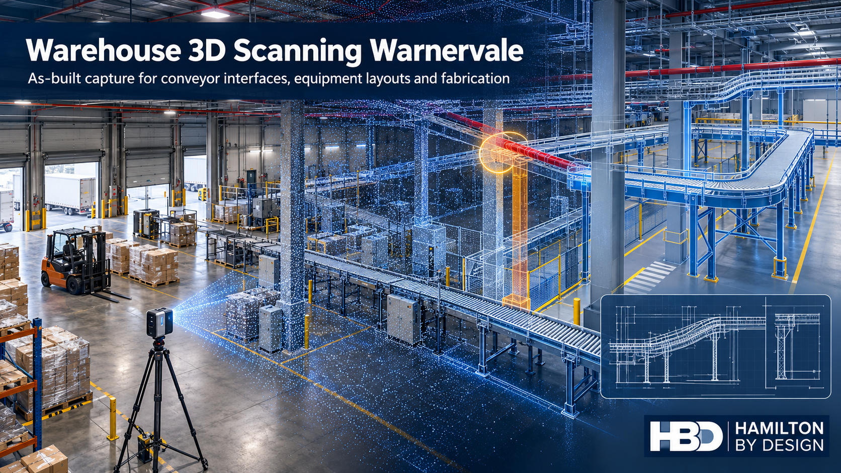
Illustration of a Warnervale warehouse showing a laser scanner, point cloud, conveyor clash and revised CAD layout.
Blue 3D LiDAR scanner icon on a tripod with scanning waves

A warehouse fit-out often begins with a clean drawing. The building on site may tell a different story. A column is slightly out of position, a service crosses the proposed conveyor route, or equipment installed after handover occupies space shown as clear on the original plan. Each difference matters when a new system must be fabricated and installed while the warehouse keeps operating.

Hamilton By Design provides warehouse 3D scanning in Warnervale, NSW, to establish the existing conditions before layouts and mechanical details are finalised. We can turn the scan into a point cloud, an as-built drawing or a CAD model suited to the decision the client needs to make. From there, our mechanical design and drafting services can support conveyor interfaces, equipment layouts and fabrication documentation.

For a new facility, the question may be, โ€œWhat was actually built?โ€ For an established distribution centre, it is more likely, โ€œWill the proposed change fit without disrupting the operation?โ€ Both questions are better answered before components arrive on site.

Why Warnervale needs its own approach

Warnervale is more than a name on a Central Coast service-area list. Its business park sits close to the M1 and Sparks Road interchange, beside Central Coast Airport and near the railway. The precinct includes established distribution activity, while the wider Warnervale area is identified for further industrial, manufacturing, logistics and warehouse uses. That creates two kinds of engineering work: adapting facilities already in use and preparing newer buildings for their first equipment fit-out.

The businesses in and around the precinct illustrate its range. Woolworths has a distribution-centre property at Warnervale. PFD Foodservice has identified a new Warnervale site, while Coastal Transport Services lists its depot and head office on Burnet Road. Sanitarium lists a Development & Innovation location at Warnervale; its listed Central Coast factory is at Berkeley Vale. These examples describe local activity, not projects undertaken by Hamilton By Design.

There is also a geographical detail worth getting right. Warnervale Business Park and Warner Business Park are different developments; the latter is in nearby Jilliby. A facility’s address and site boundaries should be confirmed before its layout, access or planning conditions are discussed.

The point where a drawing becomes an installation problem

Consider a proposed conveyor through an occupied warehouse. On a concept drawing, its route may appear straightforward. On site, the installation team must work around columns, doors, overhead services, existing machines, pedestrian routes and maintenance access. A support frame may need to land in a narrow space that has never been measured for that purpose.

An as-built scan records the visible geometry of the relevant area. The registered point cloud can then be used to review the proposed conveyor against the building and existing equipment. Depending on the project, HBD can develop plan views, sections, selected equipment models and installation details. The aim is to identify difficult interfaces while there is still time to change the design.

This is the connection between 3D LiDAR scanning in Wyong and surrounding areas and practical warehouse engineering. The scan is a starting point for decisions: where the equipment can go, what needs to be moved, which dimensions require direct verification and what the fabricator needs to know.

What should be captured in a Warnervale warehouse?

Scanning an entire building is not automatically the right scope. A project to install one transfer conveyor may need detailed coverage of its route, support locations, connection points and nearby services. A broader warehouse reconfiguration may require a coordinated record of the floor, columns, docks, major equipment and circulation spaces.

A useful scoping discussion starts with the proposed change. HBD can then identify which of the following need to be captured:

  • Building columns, walls, doors, slab levels and relevant overhead features.
  • Existing conveyors, machines, guards and access platforms.
  • Equipment connection points and spaces needed for operation or maintenance.
  • Loading and movement areas affected by a layout change.
  • Selected dimensions that must be checked directly before fabrication.

A point cloud contains a great deal of information, but it does not automatically verify every fabrication dimension. Critical interfaces should be identified early, given suitable access and checked to the tolerance required by the work. HBDโ€™s 3D scanning for fabrication service in Wyong explains how site capture can support components and installation layouts intended to fit existing assets.

From as-built scanning to a workable layout

A warehouse layout has to do more than fit equipment inside a building. It must allow materials to move through the operation and give people room to use, clean and maintain the equipment. A conveyor positioned solely by its footprint may block access to a door or leave too little room to remove a component later.

HBD can use the scan as a reference for alternative equipment positions and mechanical interfaces. The output might be a straightforward two-dimensional floor plan, a three-dimensional model of a congested area, or fabrication drawings for supports and brackets. The required level of detail depends on whether the client is exploring options, seeking approval for a layout or ready to manufacture components.

Our wider Central Coast point-cloud-to-CAD workflow connects site capture with usable models and drawings. For projects that need equipment modification as well as measurement, mechanical engineering services on the Central Coast can support the design and fabrication stages.

3D laser scanning in Warnervale is particularly useful when several contractors are working from different assumptions. A shared as-built reference helps the warehouse operator, equipment supplier, mechanical designer and fabricator discuss the same physical constraints. It also provides a baseline against which later changes can be recorded.

Five problems to resolve before a fit-out

The first problem is unreliable existing drawings. Construction drawings show design intent, while the installed facility may have changed during construction or operation. An as-built survey establishes the features relevant to the proposed work.

The second is equipment that fits on paper but clashes on site. Conveyor routes and machine envelopes should be checked against columns, services, doors and adjacent plant before supports or components are made.

Third is limited installation access. Fabrication drawings need to account for how a component will be brought into the building, positioned and connected. Measuring the final location alone may miss the route required to get it there.

Fourth is the interaction between equipment and people. A layout change can alter access to machinery or the way workers and vehicles move through an area. The operatorโ€™s risk assessment should consider those changes. Scan data and CAD layouts can help document the geometry, but the scan itself is not a safety assessment.

Fifth is the loss of a reliable engineering record. When a project finishes, its measured information can be more valuable than the original concept drawing. Subject to the clientโ€™s agreed confidentiality and retention arrangements, HBD can retain factory point clouds, machine models, conveyor layouts, CAD files, fabrication drawings and equipment-interface information for future modifications.

A record that supports the next change

Warehouses rarely stay in their original arrangement. A tenant may introduce a new product line, move a machine, alter a conveyor or change how an area is used. Each change is easier to plan when the project team can locate a dependable record of the previous one.

That does not mean modelling every bolt in the building. A useful digital record is organised around purpose: the areas captured, the date and revision, the features modelled, and any limits on how the data should be used. When fabrication is involved, the record should also distinguish between general scan geometry and dimensions specifically verified for manufacture.

For an owner or operator, this gives future teams a clearer starting point. For a fabricator, it reduces the number of assumptions hidden in a drawing. For a project manager, it makes an interface question easier to resolve before it becomes a site delay.

Frequently asked questions

Can HBD scan a warehouse that is still operating?

Yes, subject to site access, induction and a suitable scan plan. The survey can be organised around the areas needed for the project. An active site may require coordination with vehicle movements, equipment use and restricted work areas.

Does a new warehouse need as-built scanning if construction drawings already exist?

It may, particularly before closely fitting conveyors, machinery or fabricated supports are installed. The scan can check the relevant built geometry against the proposed equipment layout. The extent of scanning should reflect the fit-out risk rather than an assumption that the whole building needs a detailed model.

What is included in scan to CAD for a Warnervale factory fit-out?

That depends on the agreed deliverables. It may include a registered point cloud, a two-dimensional layout, selected three-dimensional building or machine geometry, sections through congested areas, and drawings for mechanical or fabrication work. HBD can define those outputs with the client before scanning.

Can warehouse scanning help with conveyor design?

Yes. Scanning can establish the available route and the position of existing equipment, structure and services. Mechanical design is then needed to develop the conveyor arrangement, supports and interfaces. The scan provides measured context; it does not design the conveyor by itself.

Is a point cloud accurate enough to fabricate from?

Accuracy depends on the scanner


Hamilton By Design logo displayed on a blue tilted rectangle with a grey gradient background

Contact Us – Talk To Us

Name
Would you like us to arrange a phone consultation for you?
Address

Our clients:



Industrial 3D Laser Scanning in Geebung, Virginia and Northgate: Engineering Brisbane Northโ€™s Established Manufacturing Corridor

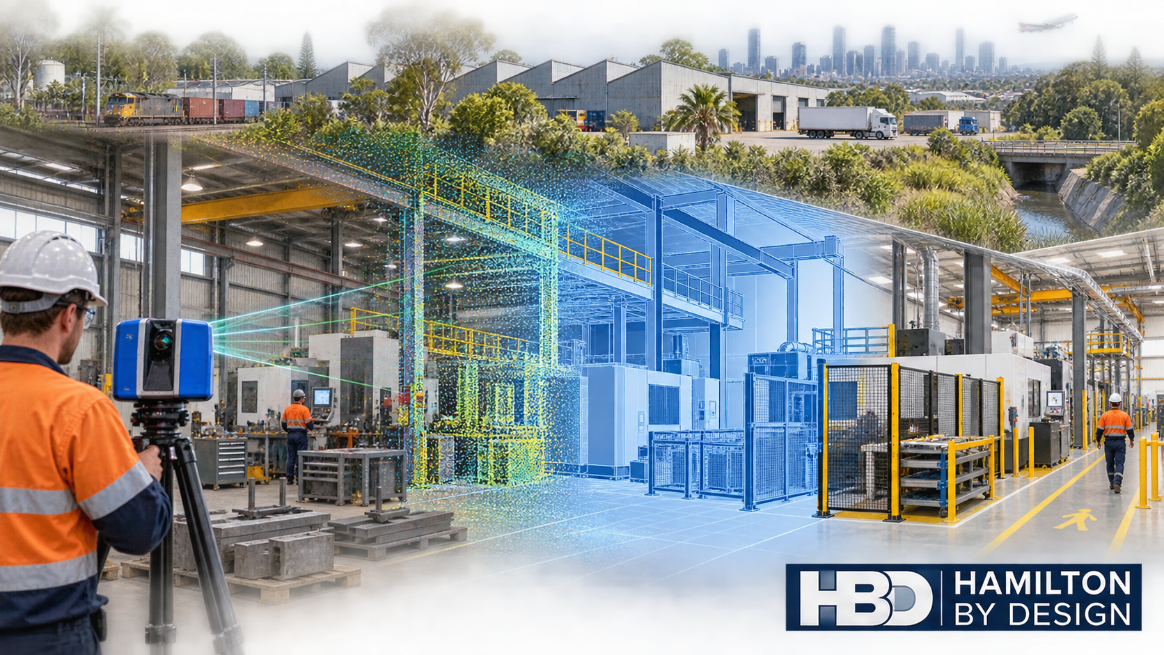
Industrial 3D laser scanning of a Brisbane north factory transitioning from point-cloud data to an engineered CAD model.
Blue 3D LiDAR scanner icon on a tripod with scanning waves

Geebung, Virginia and Northgate form one of Brisbaneโ€™s most established manufacturing and engineering corridors. Located approximately 10 to 14 kilometres north of the Brisbane CBD, these suburbs support a diverse industrial community encompassing precision machining, sheet-metal fabrication, specialist machinery manufacture, hydraulic equipment, industrial maintenance, warehousing and freight distribution.

Unlike a newly developed industrial estate, Brisbaneโ€™s northern corridor has evolved over decades. Older workshops sit alongside advanced manufacturing businesses and modern logistics facilities. Many properties have been extended, subdivided or adapted to accommodate machinery and production processes that were never anticipated when the buildings were first constructed.

This mixture creates a distinctive engineering environment. The challenge is rarely limited to designing a new machine or component. Businesses must determine how new equipment will fit within an existing factory, how it will interact with surrounding structures and services, and how it can be installed without introducing safety, access or maintenance problems.

Hamilton By Design assists manufacturers, fabricators and industrial operators through engineering-led 3D scanning services in Brisbane, reverse engineering, mechanical design, scan-to-CAD modelling, industrial drafting and as-built verification.

A manufacturing corridor with practical capability

Geebung, Virginia and Northgate should not be regarded simply as a warehouse district. The corridor contains a significant concentration of businesses involved in making, repairing and improving industrial equipment.

Local capabilities include CNC machining, aluminium casting, metal fabrication, hydraulics, special-purpose machinery, mining equipment, oil-and-gas components, material handling and equipment servicing. These operations are supported by logistics businesses, industrial suppliers, warehousing facilities and access to the broader Brisbane engineering workforce.

The corridorโ€™s location is an important part of its industrial character. Businesses have access to Sandgate Road, Gympie Road and the Gateway Motorway, with practical connections to Brisbane Airport, the Port of Brisbane and the wider South East Queensland freight network.

However, good regional access does not automatically mean that an industrial site is easy to modify. Inside individual properties, engineering teams may encounter narrow driveways, shared yards, limited truck-turning space, closely spaced buildings, congested loading areas and restricted installation routes.

These local conditions make reliable existing-site information particularly valuable.

Why existing drawings may not represent the factory today

Many industrial buildings in Geebung, Virginia and Northgate have been occupied and modified by several businesses during their working lives. Machinery may have been installed, relocated or removed. Platforms may have been extended, guards replaced, services rerouted and storage areas progressively expanded.

Original architectural drawings may still be useful, but they often do not show the current operating arrangement. Even relatively recent drawings may omit smaller modifications made during maintenance work or production changes.

This can create uncertainty when planning:

  • New manufacturing cells
  • CNC machinery installations
  • Conveyor modifications
  • Robotic equipment
  • Guarding upgrades
  • Storage and materials-handling systems
  • Pipework and ducting
  • Access platforms
  • Loading-area changes
  • Machinery relocations

Conventional tape measurements can capture individual dimensions, but they may not adequately record the relationships between machinery, columns, roof framing, services, access routes and neighbouring equipment.

Engineering-grade LiDAR scanning addresses this problem by capturing the visible facility as a coordinated three-dimensional dataset. The resulting point cloud provides a measurable record of the factory at the time of scanning.

From factory scan to usable engineering information

A point cloud is valuable, but it is not automatically an engineering solution. Its real value emerges when the captured information is interpreted and converted into suitable design deliverables.

Hamilton By Designโ€™s process can include site planning, LiDAR capture, scan registration, quality review, point-cloud preparation, CAD modelling, mechanical design and drawing production.

Depending on the purpose of the project, deliverables may include:

  • Registered E57, RCP or LAS point-cloud files
  • Two-dimensional factory layouts
  • Three-dimensional equipment and building models
  • Machinery location plans
  • General arrangement drawings
  • Equipment-clearance studies
  • Clash-detection models
  • Fabrication drawings
  • Installation reference information
  • As-built records

The required level of modelling should be selected according to the intended use. A machinery-relocation study may require accurate equipment envelopes, column locations, access routes and overhead clearances. It may not require every wall, pipe or small building feature to be modelled.

Defining this purpose before scanning helps control cost while ensuring that the information is sufficiently detailed for the decisions being made.

Supporting machinery relocation and factory upgrades

Machinery relocation involves more than checking whether a machine fits inside an available rectangle on a floor plan.

The proposed arrangement may need to account for:

  • Operator access
  • Raw-material delivery
  • Finished-product removal
  • Maintenance clearances
  • Electrical and hydraulic connections
  • Extraction or ventilation services
  • Overhead crane access
  • Forklift routes
  • Guard opening distances
  • Emergency access
  • Installation and lifting space

A three-dimensional model allows these relationships to be reviewed before equipment is disconnected or foundations are constructed.

For factories with limited shutdown windows, this is especially important. Discovering a clash during installation can extend downtime, create urgent fabrication work and delay the return to production. Capturing the existing environment early allows more of the uncertainty to be resolved during design.

Hamilton By Design can combine measured site information with scan-to-CAD reverse engineering and fabrication drawings to support the project from initial site capture through to practical installation information.

Reverse engineering for Brisbane north manufacturers

The corridorโ€™s concentration of long-established machinery creates another common problem: equipment may remain operational long after its original drawings or OEM support have disappeared.

A damaged or worn component cannot always be reproduced reliably from a few manual measurements. Its geometry may incorporate complex curves, fabricated transitions, cast surfaces, machining features or interfaces with surrounding equipment.

Hamilton By Designโ€™s reverse-engineer 3D scanning service can capture the physical component and surrounding interfaces before developing editable CAD information.

The engineering process must distinguish among:

  • Original design geometry
  • Normal manufacturing variation
  • Operational wear
  • Permanent distortion
  • Previous repairs
  • Material build-up
  • Intentional site modification
  • Damage or failure

Blindly copying a worn component may reproduce the problem that caused it to fail. Effective reverse engineering therefore requires technical judgement as well as accurate measurement.

Potential applications within the Geebungโ€“Virginiaโ€“Northgate corridor include machine guards, brackets, chutes, hoppers, wear components, hydraulic equipment, shafts, fabricated covers, equipment bases and discontinued replacement parts.

Machinery safety and maintainable access

Manufacturing upgrades can introduce hazards if safety is considered only after the production layout has been finalised.

Machinery may expose workers to:

  • Rotating components
  • Drawing-in points
  • Crushing or shearing zones
  • Unexpected movement
  • Ejected materials
  • Hot surfaces
  • Stored hydraulic or pneumatic energy
  • Restricted isolation points
  • Unsafe cleaning access
  • Falls from elevated work areas

Hamilton By Design can assist by recording the existing arrangement, identifying geometric constraints and developing practical guarding or access modifications. Depending on the equipment and project scope, relevant requirements may include the AS/NZS 4024 safety-of-machinery series and AS 1657 for fixed platforms, walkways, stairs and ladders.

The objective should not be to place an enclosure around a machine without considering how the equipment is operated. A guard that prevents maintenance, obstructs production or is difficult to remove may be bypassed by operators. Effective guarding must balance risk reduction with visibility, access, isolation, cleaning and maintenance requirements.

Consultation with operators and maintainers is therefore an essential part of the design process.

Logistics, forklifts and constrained industrial yards

The corridorโ€™s strong connection to Brisbaneโ€™s freight network creates opportunities for manufacturers and logistics operators, but it also creates risks within individual sites.

Older industrial properties may have been developed before current traffic volumes, vehicle sizes or warehouse practices were anticipated. Forklifts, trucks, pedestrians, loading activities and maintenance work may compete for the same restricted space.

Three-dimensional scanning can support the development of:

  • Loading-area layouts
  • Vehicle-clearance studies
  • Conveyor arrangements
  • Forklift and pedestrian-separation plans
  • Maintenance platforms
  • Storage-equipment layouts
  • Installation sequencing
  • Equipment-relocation studies

HBD can document the physical environment and help develop engineering controls. Operational traffic management, workplace procedures and staff consultation remain essential parts of the broader risk-management process.

A local issue that cannot be ignored: flood exposure

Parts of the greater Virginia and Geebung area are influenced by the Downfall Creek catchment. Flood exposure varies between properties, and businesses should avoid making assumptions based solely on suburb boundaries.

When a flood-affected industrial site is being upgraded, the engineering review may need to consider the location of electrical equipment, stored materials, controls, motors, valuable machinery and critical production assets.

LiDAR scanning does not replace professional flood modelling or survey control where legally defined levels are required. It can, however, create a detailed spatial record of floors, equipment positions, access routes and building features. This information may assist other specialists and the facility owner when considering resilience measures.

For local manufacturers, this is a genuine regional considerationโ€”not a generic statement that applies equally to every industrial suburb.

Preserving industrial knowledge through controlled data

A point cloud and CAD model can remain valuable after the immediate project has finished. When properly managed, the dataset becomes part of the organisationโ€™s engineering knowledge.

Hamilton By Design can retain agreed project information such as:

  • Factory point clouds
  • Machinery scans
  • Equipment layouts
  • Site photographs
  • Replacement-part CAD
  • Guarding surveys
  • Fabrication drawings
  • Design assumptions
  • Issued revisions
  • As-built records

This is particularly useful for businesses that have historically relied on the knowledge of a small number of experienced employees.

When those employees retire or leave, undocumented information about machinery, previous modifications and equipment interfaces can disappear with them. A controlled digital record helps transfer that knowledge into a form that can be reviewed and reused.

Engineering services for Geebung, Virginia and Northgate

Hamilton By Design can support Brisbane north industrial clients with:

  • Workshop and factory scanning
  • Machinery and equipment layouts
  • Brownfield plant-upgrade design
  • Scan-to-CAD modelling
  • Reverse engineering
  • Mechanical design and drafting
  • Machine-guarding modifications
  • Platforms and maintenance access
  • Conveyor and chute modifications
  • Fabrication drawings
  • As-built verification
  • Clash detection
  • Installation planning
  • Engineering-data and revision control

Applicable standards depend on the equipment and project. They may include AS/NZS 4024, AS 1657, AS 4991, AS 3990, AS 4100, AS/NZS 1554, AS 4041, AS 1210 and the AS 1418 and AS 2550 series.

Hamilton By Design provides mechanical engineering and drafting services. Where structural certification, specialised statutory approval or Queensland professional engineering registration is required, the appropriate registered professional must be engaged and involved in accordance with the applicable legislation.

Frequently asked questions

What can be captured during an industrial 3D laser scan?

LiDAR can capture visible factory geometry, including floors, walls, columns, roof structures, machinery, conveyors, platforms, pipework, ducting, loading areas and access routes. Hidden or internal features may require drawings, physical inspection or another measurement method.

Can a factory continue operating while it is scanned?

Often it can. The scanning plan can be arranged around production, vehicle movements and restricted areas. Moving people, forklifts or products may create temporary visual obstructions, so some areas may need to be captured during quieter periods or planned shutdowns.

Can HBD convert a factory scan into a two-dimensional layout?

Yes. Registered point-cloud information can be used to develop equipment layouts, general arrangements, elevations and sections. The required drawing content and accuracy should be agreed before scanning.

Can scanning help determine whether new machinery will fit?

Yes. The proposed machine envelope can be positioned within the existing-condition model to review columns, walls, overhead structures, neighbouring machinery, access paths and maintenance clearances. Service connections and installation requirements must also be considered.

Can worn machinery components be reverse engineered?

Yes, where the available geometry and condition permit. The process should identify wear, damage, distortion and prior repairs rather than automatically reproducing every scanned surface.

Does a point cloud replace engineering design?

No. A point cloud records measured visible geometry. Engineering design is still required to define loads, materials, tolerances, safety requirements, fabrication details and compliance obligations.

Can HBD produce fabrication drawings?

Yes. HBD can develop suitable mechanical and fabrication documentation from verified scan data and approved design information. The precise deliverables depend on the asset, required design responsibility and certification pathway.

Which Australian Standards apply to a factory upgrade?

There is no single standard covering every factory modification. Relevant requirements may include machinery safety, fixed access, lifting equipment, welding, mechanical-equipment steelwork, structural design or pressure equipment standards. The applicable standards should be established during the projectโ€™s scope and risk review.

Can scan data be retained for future projects?

Yes. Agreed point clouds, CAD models, photographs and controlled drawings can be retained as an engineering reference. File ownership, access, formats and retention periods should be documented in the proposal.

Building better upgrades from measured information

Geebung, Virginia and Northgate combine the strengths of an established manufacturing district with the pressures of modern industrial development. Advanced machinery and automated systems must often be fitted into buildings that have already experienced decades of occupation and modification.

In this setting, assumptions carry real consequences. An incorrect dimension can cause a fabricated component not to fit. An incomplete layout can obstruct maintenance. An overlooked access requirement can turn a straightforward installation into an extended shutdown.

Engineering-led 3D scanning provides a reliable starting point by capturing the facility as it exists today. When combined with mechanical design, reverse engineering, drafting and controlled engineering data, it can help Brisbane north manufacturers plan upgrades with greater confidence.

For businesses considering machinery relocation, factory modification, guarding improvements or replacement-component development, Hamilton By Design can provide a connected workflow from site capture through to practical engineering documentation.


Hamilton By Design logo displayed on a blue tilted rectangle with a grey gradient background

Contact Us – Talk To Us

Name
Would you like us to arrange a phone consultation for you?
Address

Our clients:



Sydney Manufacturing Upgrades: Why 3D LiDAR Data Should Come Before Production Changes

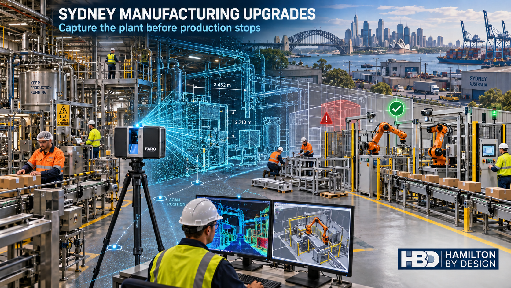
3D LiDAR scanning of a Sydney manufacturing facility with robotic production cells, point-cloud data and the Hamilton By Design logo.
Blue 3D LiDAR scanner icon on a tripod with scanning waves

Australian manufacturing is entering a period of accelerated technological and operational change. Automation, artificial intelligence, mobile robotics and data-driven production systems are creating opportunities for Sydney manufacturers to improve productivity, production quality and competitiveness.

However, introducing new technology into an existing factory is rarely as simple as purchasing a machine and installing it.

New production equipment must fit within an established operating environment containing conveyors, services, access platforms, structural elements, pipework, electrical infrastructure and other machinery. If the existing factory is not accurately documented before an upgrade begins, installation problems can lead to delays, rework and extended production shutdowns.

For manufacturers, lost time during an upgrade means lost production. Depending on the facility, even a few additional hours of downtime can affect output targets, labour utilisation, customer deliveries and revenue.

The September 2026 edition of Manufacturersโ€™ Monthly included an article titled โ€œThe trends shaping Australian manufacturing.โ€ The article discussed the growing importance of automation, artificial intelligence, mobile robotics and data-driven production systems within Australian industry.

It also made an important observation: successful automation does not depend solely on purchasing technology. Manufacturers need reliable systems supported by engineering capability, maintenance, service and long-term relationships.

This is particularly relevant to brownfield manufacturing facilities across Sydney.

Many factories were constructed or expanded over several decades. Machines may have been relocated, production lines modified, services rerouted and safety systems upgraded without every alteration being incorporated into the original drawings.

Consequently, the available drawings may no longer represent the factory as it exists today.

Before a manufacturer invests in new automation or production equipment, it is important to establish a reliable record of the existing facility. Three-dimensional LiDAR scanning provides a practical way to collect that information.

The industrial diversity of Sydney

Sydneyโ€™s manufacturing sector is not concentrated in a single precinct. It extends across Western Sydney, South-West Sydney, the Parramatta industrial corridor, the inner south, the Sutherland Shire and the Northern Beaches.

These areas contain food and beverage manufacturers, pharmaceutical businesses, metal fabricators, plastics manufacturers, logistics facilities, engineering workshops, chemical-processing operations and businesses supplying construction, transport, defence and infrastructure projects.

The requirements of each facility are different, but many face a common challenge: upgrading an operating factory while minimising disruption to production.

A manufacturer in Wetherill Park may be rearranging machinery to accommodate a new production cell. A business requiring reverse engineering in Smithfield may need to reproduce an obsolete component. A facility considering 3D laser scanning in Ingleburn or Minto may be planning a conveyor extension or automation project.

In each case, reliable existing-condition information provides the foundation for better planning.

What is 3D LiDAR scanning?

A terrestrial 3D LiDAR scanner uses laser measurements to capture the visible surfaces of a factory, production line or industrial facility. Each scan records millions of measured points, collectively forming a three-dimensional point cloud.

The resulting dataset can capture:

  • existing production equipment;
  • conveyors and transfer points;
  • pipework and ducting;
  • access platforms, stairs and handrails;
  • columns, beams and visible building geometry;
  • floor levels and penetrations;
  • overhead services;
  • electrical cabinets;
  • maintenance access areas;
  • machine interfaces; and
  • restricted installation spaces.

Multiple scan positions can be registered together to create a coordinated digital record of the required work area.

The point cloud can then support equipment layouts, clash reviews, three-dimensional CAD models, general-arrangement drawings and installation planning.

This approach is applicable to established facilities such as those requiring industrial 3D laser scanning in Silverwater and to machinery-focused projects requiring reverse engineering in Seven Hills.

Why scanning should happen before upgrade design

A production upgrade normally begins with a desired outcome. The manufacturer may want to:

  • increase production capacity;
  • replace unreliable equipment;
  • reduce manual handling;
  • introduce robotics;
  • improve guarding;
  • modify product flow;
  • lower energy consumption;
  • improve cleaning access;
  • introduce condition monitoring; or
  • reconfigure the line for a different product.

The design team must then determine how the proposed equipment will interact with the existing facility.

When that assessment is based on outdated drawings or isolated manual measurements, important constraints may remain undiscovered until fabrication or installation.

Typical problems include:

  • equipment that does not fit through the proposed installation route;
  • conveyors that do not align with existing machinery;
  • pipework or ducting occupying the required space;
  • columns conflicting with new equipment;
  • insufficient maintenance clearance;
  • access platforms obstructing robotic movement;
  • floor penetrations in unsuitable locations;
  • incorrect equipment-interface heights;
  • inaccurate machine centre lines; and
  • guarding that cannot be installed as designed.

A detailed LiDAR survey does not remove every project risk, but it substantially improves the quality of the existing-condition information available to designers, fabricators and installers.

Businesses considering 3D laser scanning in Revesby, factory scanning in Chipping Norton or 3D laser scanning in Prestons can use the resulting point cloud to assess proposed equipment against measured site geometry before a shutdown begins.

Lost upgrade time becomes lost production

Production downtime is one of the most significant risks associated with brownfield factory upgrades.

Manufacturers may schedule installation work during a weekend, planned maintenance period or annual shutdown. These windows are often tightly controlled because production must resume by a defined time.

If a dimensional error is discovered during installation, the consequences can extend beyond the cost of modifying one component. A delay can affect the entire commissioning sequence.

For example, a support frame may need to be cut and altered because it conflicts with an existing service. This can delay equipment installation, guarding, electrical work, testing and commissioning. Production cannot restart until the complete system is safe and operational.

The resulting cost may include:

  • lost production output;
  • additional contractor hours;
  • extended crane or access-equipment hire;
  • emergency fabrication;
  • express freight;
  • delayed commissioning;
  • missed customer deliveries;
  • idle production employees; and
  • disruption to downstream operations.

The cost of collecting accurate site data before design is generally small compared with the potential cost of an unplanned shutdown extension.

This consideration is especially important for high-throughput logistics and manufacturing facilities around Eastern Creek, port-related and process operations requiring industrial scanning in Botany, and manufacturers planning factory scanning in Smeaton Grange.

Moving uncertainty out of the shutdown window

The purpose of pre-upgrade scanning is not merely to produce an impressive point-cloud image. Its practical purpose is to move uncertainty away from the shutdown window and into the planning stage.

Before production stops, the project team can examine:

  • whether the new equipment will fit;
  • whether existing services must be relocated;
  • whether the proposed installation route is practical;
  • how the new equipment will connect to the existing line;
  • whether maintenance and cleaning access will remain available;
  • whether guarding can be installed;
  • where temporary equipment can be positioned; and
  • which components should be prefabricated.

Questions resolved during design are generally less expensive than problems discovered during installation.

For manufacturers using 3D laser scanning in Glendenning, reverse engineering in St Marys or 3D laser scanning in Yennora, the same principle applies: capture the existing conditions before committing to the final arrangement.

Supporting design while the production line remains operational

One of the principal advantages of 3D scanning is that much of the upgrade planning can occur while the existing production line remains operational.

Subject to site access and safety requirements, the facility can be scanned during normal production, a short maintenance window, a weekend or a planned low-activity period. The resulting point cloud provides a reference that the project team can continue using after leaving the site.

Designers can use the dataset to:

  • establish the existing production-line arrangement;
  • determine equipment footprints and interface positions;
  • examine installation and removal routes;
  • assess access for cranes, forklifts and elevated work platforms;
  • plan temporary works and equipment laydown areas;
  • identify potential spatial clashes;
  • develop preliminary equipment arrangements;
  • prepare fabrication drawings; and
  • coordinate proposed changes with the existing plant.

This allows more decisions to be made before manufacturing or installation begins.

The approach is relevant to machinery and component projects requiring reverse engineering in Milperra or reverse engineering in Condell Park, as well as facility-layout projects requiring 3D laser scanning in Villawood.

Existing drawings may not represent the existing plant

Many brownfield factories have drawing sets containing valuable information. However, the presence of drawings does not automatically mean that they accurately reflect current site conditions.

A facility may have undergone years of incremental changes, including:

  • replacement machines with different footprints;
  • locally fabricated platforms;
  • undocumented pipework;
  • revised production-line layouts;
  • temporary modifications that became permanent;
  • new electrical cabinets;
  • relocated access routes;
  • additional guarding; and
  • building alterations.

These changes can create a gap between the documented factory and the physical factory.

Scanning helps identify that gap. Existing drawings can still be used, but they can be reviewed against measured conditions rather than accepted without verification.

This can be valuable in established industrial areas such as Rydalmere, Camellia and Granville, where industrial properties may have undergone multiple changes during their operating lives.

From point cloud to installation planning

After scanning, the registered point cloud can be imported into suitable engineering and design platforms. Depending on the project requirements, the data may be used directly as a spatial reference or converted into selected CAD geometry.

Not every visible object must be modelled. The level of modelling should suit the decisions the project team needs to make.

For example:

  • a preliminary layout may require equipment envelopes and building geometry;
  • a conveyor modification may require accurate transfer points, centre lines and support locations;
  • a pipework project may require pipe centre lines, flange locations and nearby obstructions;
  • a robotic cell may require a detailed working envelope and guarding layout;
  • a replacement component may require higher-resolution scanning or direct measurement; and
  • a fabrication package may require verified interfaces and defined tolerances.

The most effective scope is based on the project outcome rather than an assumption that every captured surface must become a detailed solid model.

Manufacturers planning projects around Blacktown, Emu Plains and Penrith can use this staged approach to match the amount of modelling to the upgradeโ€™s actual requirements.

Supporting Western Sydneyโ€™s manufacturing growth

Western Sydney continues to accommodate major industrial, logistics and advanced-manufacturing activity. New development is occurring alongside older facilities that require continuing upgrades.

For established plants, the challenge is often to introduce modern production systems within buildings that were not originally designed for them. For new facilities, accurate scanning can still assist when equipment installation, services and building works have developed separately.

Hamilton By Design provides industrial scanning across Western Sydney to support the transition from existing-condition capture to engineering documentation.

Growth areas such as Marsden Park and Riverstone and the Mamre Road and Kemps Creek industrial precinct are likely to contain a combination of new facilities, expanding operations and future production changes.

Collecting and retaining accurate spatial data can help these businesses manage later modifications without repeatedly starting from incomplete information.

South and South-West Sydney manufacturing

South and South-West Sydney contain a broad range of food-production facilities, packaging operations, engineering workshops, warehouses and light-manufacturing businesses.

Plants in these areas may face restricted access, congested production floors and limited shutdown periods. These conditions increase the value of completing measurement and design work before installation begins.

Relevant local capabilities include:

Scanning may be used to document a single machine, a production cell or a larger operating area. The correct extent depends on the proposed upgrade and the equipment or services likely to be affected.

Inner-south and airport industrial areas

The industrial areas around Alexandria, Rosebery, Mascot and Botany combine older industrial buildings with newer logistics, technology, food-production and commercial facilities.

These properties can present particular upgrade challenges, including restricted delivery access, limited internal space, overhead services and buildings that have undergone multiple changes of use.

Industrial engineering support in Alexandria and Rosebery can help businesses document existing machinery and plan modifications. Similarly, industrial 3D scanning in Mascot can assist with factory layouts, equipment installation and access planning.

Where installation access is restricted, the point cloud can also help the project team investigate how equipment will be delivered, moved through the building and positioned without relying solely on assumptions made from a floor plan.

Sutherland Shire and southern industrial facilities

The Sutherland Shire contains engineering businesses, manufacturers, processing facilities and workshops serving Sydneyโ€™s construction, marine and industrial markets.

Projects may involve production machinery, pumping equipment, fabricated components, plant modifications or replacement parts.

Hamilton By Design supports this region through services including:

The same principle remains central: the quality of the upgrade decision depends partly on the quality of the information used to describe the existing plant.

Northern Sydney and Northern Beaches manufacturing

Although Western and South-West Sydney contain many of the cityโ€™s major industrial precincts, specialist manufacturers and engineering businesses also operate across Northern Sydney and the Northern Beaches.

These businesses may work from smaller, space-constrained facilities where equipment access and floor-area efficiency are critical.

Local services include:

In smaller factories, a poorly planned equipment change can consume valuable production area or restrict access to surrounding machinery. A three-dimensional survey helps assess spatial relationships before new equipment is ordered or fabricated.

Connecting the physical factory with digital manufacturing

The move toward smarter manufacturing depends on reliable information about physical assets.

Automation systems may produce large volumes of operational data, but an upgrade project still requires an accurate understanding of where equipment is located and how it interfaces with the surrounding facility.

A registered point cloud can provide the geometric foundation for a digital representation of the factory. Depending on the project requirements, the data may support:

  • scan-to-CAD modelling;
  • production-line layouts;
  • digital-twin development;
  • robotic-cell planning;
  • conveyor modifications;
  • clash detection;
  • machine-guarding reviews;
  • fabrication drawings;
  • shutdown planning; and
  • future asset-management activities.

This can be particularly valuable for manufacturers operating facilities that have grown through multiple stages of expansion.

Instead of starting each upgrade with another series of disconnected measurements, the business can retain a controlled digital record and update it as the facility changes.

Data collection must be planned around the intended outcome

Not every scanning project requires the same level of detail.

A general factory-layout survey differs from a dimensional inspection or metrology survey of a machine component. Similarly, a scan intended for equipment-placement planning may not capture every concealed service or individual fastening detail.

Before scanning begins, the manufacturer and scanning provider should agree on:

  • the purpose of the proposed upgrade;
  • the decisions the data must support;
  • the required deliverables;
  • the areas that must be captured;
  • critical equipment interfaces;
  • required measurement confidence;
  • production and access restrictions;
  • areas concealed by guarding or stored materials;
  • whether equipment will be operating during scanning;
  • required file formats; and
  • how the data will be stored for future projects.

Clear scope definition helps ensure that the collected data is suitable for the engineering decisions it will support.

Capturing machine interfacesโ€”not just the building

A factory scan should be planned with an understanding of the proposed mechanical work.

A survey that captures the overall building but misses critical equipment interfaces may not provide enough information for fabrication or installation.

Depending on the project, important details may include:

  • machine centre lines;
  • mounting surfaces;
  • conveyor elevations;
  • shaft positions;
  • flange faces;
  • bolt-hole locations and clocking;
  • pipe centre lines;
  • connection points;
  • guarding interfaces;
  • access requirements; and
  • maintenance-removal paths.

Plant condition must also be considered. Product build-up, stored materials, temporary equipment and guarding can obscure important geometry. The scanning plan should identify whether cleaning, access or limited equipment removal is required before data capture.

This is why industrial scanning benefits from being undertaken with the intended engineering and fabrication workflow in mind.

From point cloud to manufacturable outcome

Collecting the scan is only the first stage.

The information must be interpreted by people who understand machinery, fabrication, installation and industrial workflows. A point cloud is valuable, but the final benefit comes from using it to support a practical engineering outcome.

Hamilton By Design combines 3D LiDAR scanning with mechanical design, drafting, reverse engineering and fabrication support. This provides a connected workflow from existing-condition capture through to CAD development and upgrade documentation.

A typical process may include:

  1. Define the production problem and required outcome.
  2. Identify the critical equipment and facility interfaces.
  3. Scan the existing factory, machinery or production line.
  4. Register and review the point-cloud data.
  5. Develop the required layouts or CAD models.
  6. Insert the proposed equipment into the existing environment.
  7. Review access, interfaces, clearances and potential clashes.
  8. Prepare drawings to support fabrication and installation.
  9. Confirm the shutdown and installation sequence.
  10. Retain the approved information for future upgrades.

Keeping scanning and mechanical design within a connected workflow helps maintain responsibility for how the captured information is interpreted and used.

A practical first step for Sydney manufacturers

Before changing a production line, installing automation or ordering new machinery, manufacturers should first establish whether their existing facility information is accurate enough to support the proposed decision.

Useful questions include:

  • Do the existing drawings reflect current site conditions?
  • Have previous modifications been documented?
  • Are the machinery interfaces accurately recorded?
  • Is the proposed installation route known?
  • Have maintenance and cleaning clearances been considered?
  • Can the equipment be prefabricated confidently?
  • Have potential clashes been reviewed before the shutdown?
  • Will the resulting information be retained for later upgrades?

If the answers are uncertain, collecting 3D LiDAR data can provide a stronger starting point.

The objective is not simply to create a point cloud or a three-dimensional model. The objective is to use reliable information to make better engineering decisions, reduce installation risk and protect production time.

In manufacturing, time lost during an upgrade is rarely limited to the installation team. It can become lost output, delayed orders, additional labour and reduced revenue.

Capturing the existing factory before designing the upgrade helps move uncertainty away from the shutdown windowโ€”when every hour mattersโ€”and into the planning stage, where problems are generally easier and less expensive to resolve.

Frequently asked questions

Why should a factory be scanned before an equipment upgrade?

Scanning establishes a measured record of the existing factory, machinery and visible services. This helps designers evaluate equipment fit, access, interfaces and potential clashes before fabrication or installation begins.

Can a factory be scanned while production is operating?

In many cases, yes. The scanning approach must be coordinated with site safety, access requirements, moving machinery and personnel. Some areas may need to be captured during a maintenance period or temporary shutdown.

Does LiDAR scanning eliminate the need for site verification?

No. LiDAR scanning improves the available information, but critical interfaces, concealed conditions and fabrication dimensions may still require targeted verification. The required checks should be defined according to the project risk and intended deliverables.

Can point-cloud data support new machinery layouts?

Yes. Point-cloud data can be used as a spatial reference for positioning proposed machines, conveyors, platforms, pipework and guarding within the existing facility.

Can scanning help shorten a shutdown?

Scanning itself does not guarantee a shorter shutdown. However, it can allow more design, coordination, clash review and prefabrication to occur before production stops, reducing the likelihood of avoidable installation delays.

Can the scan data be retained for future upgrades?

Yes. The point cloud, CAD models and associated drawings can form part of the facilityโ€™s controlled engineering record. The retained data should include appropriate file management, revision control and notes explaining the captured scope and date.

Is 3D LiDAR suitable for reverse engineering individual parts?

Terrestrial LiDAR is generally suited to facilities, machinery arrangements and larger equipment. Smaller or detailed components may require a metrology-grade scanner, close-range scanner, conventional measurement or a combination of methods.

What information should be provided before requesting a scan?

The manufacturer should explain the purpose of the upgrade, the area involved, the required deliverables, critical interfaces, access restrictions, planned installation date and available shutdown window. This allows the survey and modelling scope to be matched to the required outcome.

Protect production by improving information

Sydney manufacturers are being encouraged to adopt smarter systems, automation and more data-driven production methods. These technologies offer significant opportunities, but they must be integrated into real factories containing existing equipment, undocumented changes and operational constraints.

Reliable spatial data provides a bridge between upgrade ambition and installation reality.

By scanning before designing, manufacturers can better understand their existing plant, coordinate new equipment, identify likely conflicts and prepare more of the work before production stops.

The principle is straightforward:

Capture the factory. Plan the upgrade. Resolve the conflicts. Then interrupt production.

That sequence cannot remove every project risk, but it can prevent avoidable uncertainty from consuming valuable shutdown time.

Article referenced: โ€œThe trends shaping Australian manufacturing,โ€ Manufacturersโ€™ Monthly, September 2026, p. 4.


Hamilton By Design logo displayed on a blue tilted rectangle with a grey gradient background

Contact Us – Talk To Us

Name
Would you like us to arrange a phone consultation for you?
Address

Our clients:


Factory Scanning and Reverse Engineering in Darra and Richlands

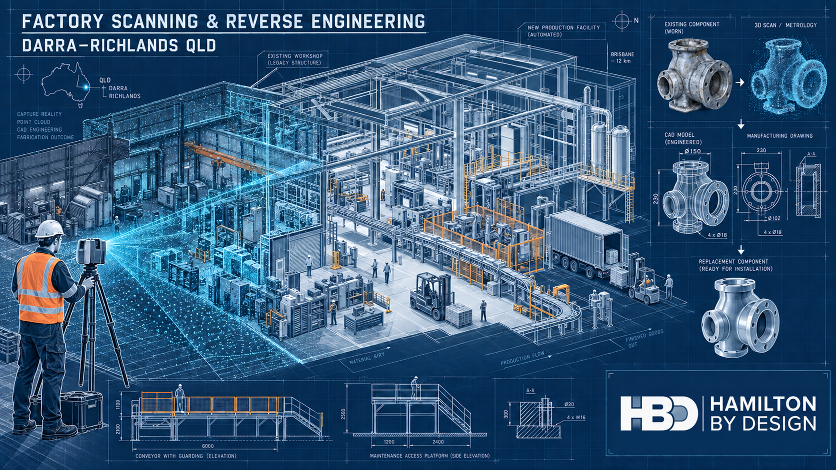
Technical drawing showing factory 3D laser scanning, point-cloud capture and machinery reverse engineering in Darra and Richlands, Queensland.

Capturing Brisbaneโ€™s industrial westโ€”from established workshops to advanced production facilities

Blue 3D LiDAR scanner icon on a tripod with scanning waves

Darra and Richlands occupy an important place in Brisbaneโ€™s industrial story. Darra developed through rail-connected brick, cement and heavy industrial activity, while neighbouring Richlands has grown into a major location for manufacturing, logistics, food and beverage production and advanced materials.

Together with Wacol, these suburbs form a connected industrial corridor rather than two isolated business districts.

That distinction matters when planning engineering work. A factory in this corridor may occupy a modern warehouse, an older purpose-built plant or a building that has been extended and repurposed several times. Machinery may have moved while services, platforms and redundant foundations remained. Original drawings may exist, but they do not always describe the factory as it stands today.

Hamilton By Design assists asset owners, manufacturers, maintenance teams and fabricators with factory scanning and reverse engineering in Darra and Richlands. Our work combines reality capture with practical mechanical understanding, turning physical plant and machinery into useful point clouds, CAD models, equipment layouts and fabrication drawings.

An industrial corridor shaped by movement and manufacturing

Darraโ€™s industrial character predates many of Brisbaneโ€™s newer business parks. Its railway connection supported early manufacturing, while the former Queensland Cement and Lime works became an important part of the districtโ€™s twentieth-century development.

The cement plant once used a long conveyor system between the Brisbane River and the Darra worksโ€”an early example of industrial infrastructure responding to geography, materials handling and production demand.

Richlands presents the contemporary side of the same story. The suburb accommodates large manufacturing and distribution facilities, including high-throughput beverage production and logistics activities supporting the nearby Wacol truck-manufacturing cluster. It is also attracting newer fields such as graphene production and advanced materials.

This produces an unusual industrial mix: legacy buildings, modern automated production lines, local workshops, major distribution facilities and nationally significant manufacturers all operate within the wider corridor.

The resulting engineering problems are rarely generic. They are connected to the condition, history and operating constraints of each site.

Why accurate factory information matters

A drawing can appear precise without being accurate.

Dimensions may have been taken from an early architectural plan, a previous tenancy layout or a machinery supplierโ€™s proposal. Columns, services and equipment may be shown in their intended positions rather than their final installed positions. Later modifications may never have been added to the drawing set.

For a preliminary concept, these differences may initially seem minor. During fabrication or installation, however, a misplaced column, an unrecorded pipe or a changed mounting point can become expensive.

These discrepancies can cause:

  • A conveyor section not to fit
  • A fabricated frame to clash with existing services
  • A replacement component to misalign with adjoining equipment
  • A machine to be too large for the proposed installation route
  • Access to a valve, bearing or motor to become restricted
  • A shutdown to be extended while steelwork is modified on site

Engineering-led 3D laser scanning provides a reliable record of visible existing conditions.

A factory survey can capture building geometry, machinery, conveyors, platforms, pipework, structural steel and surrounding obstructions in a coordinated point cloud.

Scanning does not remove the need for engineering judgement or critical manual measurements. It does, however, provide a much stronger foundation than designing from incomplete drawings and isolated tape measurements.

From point cloud to practical factory planning

The value of a factory scan is not simply the visual impact of a coloured point cloud. Its real value comes from how the information is interpreted and used.

Hamilton By Design can use registered scan data to develop:

  • Existing-condition factory plans
  • Machinery and production-line layouts
  • Building sections and elevations
  • Equipment-clearance studies
  • Conveyor and transfer arrangements
  • Installation and removal-path assessments
  • Models of selected machinery and structures
  • As-built drawings for future modifications

For a plant-layout project, the scan may be used as the spatial reference while simplified equipment envelopes are developed for arrangement planning.

This allows alternative layouts to be tested against actual columns, walls, mezzanines, accessways and existing services.

The level of modelling should suit the decision being made. A machinery-relocation study may only require reliable equipment envelopes, maintenance clearances and connection points. Detailed fabrication requires closer modelling of interfaces, supports, fasteners and critical dimensions.

Defining that distinction early avoids spending money modelling features that do not influence the engineering outcome.

Reverse engineering machinery and replacement components

Factories in Darra and Richlands often depend on equipment that has remained productive long after its original drawings or suppliers have disappeared.

A failed component may be obsolete, imported with a long lead time or previously modified to suit the site. In some cases, the physical component may be the only reliable source of dimensional information.

Reverse engineering can help recover the information needed to manufacture a replacement.

Depending on the componentโ€™s size, complexity and required accuracy, the process may combine laser scanning, metrology scanning, manual measurement, photographs and engineering inspection.

Hamilton By Designโ€™s reverse-engineering and 3D-scanning services can support items such as:

  • Rollers, pulleys and shafts
  • Brackets, frames and supports
  • Housings and covers
  • Chutes and hoppers
  • Guards and access panels
  • Machine bases and mounting plates
  • Worn or obsolete manufactured components
  • Jigs, fixtures and special-purpose tooling

Good reverse engineering is not blind copying.

A worn part records both its original function and the effects of service. Wear, distortion, corrosion and earlier repairs must be considered before deciding which surfaces should be reproduced and which should be restored.

Critical dimensions, material requirements, tolerances and mating interfaces should be agreed as part of the engineering scope.

Mechanical design for brownfield factories

Brownfield mechanical design occurs inside an environment that already has operating rules, physical constraints and production priorities.

A technically sound concept must still be accessible, maintainable, fabricable and capable of being installed safely.

Hamilton By Design provides mechanical engineering consulting for plant and machinery modifications, including:

  • Conveyors and conveyor modifications
  • Chutes, hoppers and transfer arrangements
  • Machinery-support frames
  • Pump and equipment skids
  • Guarding systems
  • Access improvements
  • Replacement assemblies
  • Production-line modifications
  • Machinery relocation
  • Brownfield plant upgrades

Scan data can be incorporated into the design environment so that proposed equipment is reviewed in relation to the real factory.

This approach is particularly useful when a project involves:

  • Adding equipment to a crowded production area
  • Relocating machinery within an existing building
  • Connecting a new conveyor to an older production line
  • Replacing equipment during a limited shutdown
  • Designing around services that cannot be moved
  • Improving maintenance access without reducing production space
  • Planning an installation before existing equipment is removed

The result should be more than a model that fits on a computer screen. It should provide a traceable path from the existing condition through design review to fabrication and installation.

Mechanical drafting and fabrication documentation

Manufacturers and fabricators require clear documentation that communicates what must be built.

Depending on the agreed scope, Hamilton By Design can prepare:

  • General arrangement drawings
  • Fabrication drawings
  • Workshop details
  • Machined-component drawings
  • Sheet-metal developments
  • Material and component schedules
  • Bills of materials
  • Cutting information
  • Installation drawings
  • As-built documentation
  • Revision-controlled drawing registers

Our fabrication and product-design services connect the site-capture and design stages with the practical information required by the workshop.

Deliverables may include native CAD files, STEP or Parasolid models, DXF profiles and controlled PDF drawing packages.

Mechanical drawings may be developed with reference to the applicable parts of the AS 1100 technical-drawing series. Fabricated steelwork may also require consideration of AS/NZS 1554, AS 4100 or AS 3990, depending on its function and classification.

The applicable standards and required level of engineering verification must be established for each project rather than assumed from the drawing type alone.

Hamilton By Design provides mechanical engineering and structural drafting within its areas of competence. Where a project requires statutory structural certification, specialist electrical design or another regulated discipline, review should be completed by an appropriately qualified practitioner.

Machinery guarding and safer access

Machinery-safety problems often emerge gradually.

A motor is replaced, a platform is added or a conveyor is extended. A guard may then be cut back to clear the modification, or it may be removed so frequently for maintenance that it is eventually left off.

Hamilton By Design provides machine-guarding design and engineering for manufacturing and fixed-plant environments.

A site assessment can consider exposed:

  • Belts and chains
  • Pulleys and rollers
  • Shafts and couplings
  • Drive assemblies
  • Conveyor nip points
  • Rotating components
  • Cutting or crushing mechanisms
  • Pneumatic and hydraulic movement

The assessment should also consider how operators, cleaners and maintenance personnel interact with the equipment.

Potential improvements can include fixed guards, removable panels, mesh enclosures, access gates, inspection openings, mounting frames and maintenance-friendly modular arrangements.

Three-dimensional scanning is particularly useful where new guards must fit around irregular machinery, pipes, cable trays, platforms or nearby structural members.

Relevant requirements may include the AS/NZS 4024 Safety of Machinery series, AS 1755 for conveyor safety and Queensland work health and safety obligations. Platforms, stairs, walkways and ladders may require consideration of AS 1657.

Guarding remains only one part of the risk-control system. Isolation, interlocks, control-system safety, operating procedures, training and inspection must also be addressed by the appropriate parties.

Supporting logistics and materials movement

Richlands is also a substantial logistics location.

Warehouses and distribution facilities face engineering issues that differ from process plants but still depend on accurate spatial information. Vehicle movement, loading docks, conveyors, pallet handling, pedestrians and maintenance activities compete for limited space.

Factory and warehouse scanning can support:

  • Loading-area layouts
  • Conveyor coordination
  • Fixed-equipment planning
  • Equipment and racking interface checks
  • Forklift and pedestrian-separation studies
  • Access-platform planning
  • Maintenance-clearance reviews
  • Tenancy modifications
  • Warehouse automation projects
  • As-built documentation

Depending on the scope, relevant standards may include AS 1657 for fixed access, AS 1755 and AS/NZS 4024 for conveyors and machinery, AS 4084 for steel storage racking and the applicable parts of AS 2890 for vehicle facilities.

Specialist traffic, racking, fire, building and structural advice should be obtained where those disciplines fall outside the agreed mechanical-engineering scope.

The five recurring problems facing industrial sites

1. Missing or outdated drawings

Older factories often accumulate changes that are never incorporated into the original drawing package. New projects then begin with uncertain dimensions and incomplete information.

Scanning provides a record of the visible installed condition from which updated layouts and as-built documents can be developed.

2. Obsolete replacement components

A component may no longer be supported by its manufacturer, or a replacement may have an unacceptable delivery period.

Reverse engineering can recover its geometry and provide CAD models or manufacturing drawings, subject to verification of its material, function and critical tolerances.

3. Congested machinery layouts

New equipment must often fit around production machinery, services, structures and accessways that cannot be readily relocated.

A coordinated point cloud allows proposed equipment to be reviewed against the existing environment before fabrication begins.

4. Guarding and access deficiencies

Machinery modifications can create new hazards or make older guards ineffective. Poorly designed guards may also interfere with routine inspection, cleaning and maintenance.

An engineering-led review can help develop controls that consider both worker safety and the practical operation of the plant.

5. Shutdown and installation risk

Unexpected conditions discovered during a shutdown can delay installation and production restart.

Scanning, interface verification, clash review and controlled fabrication drawings help move more decisions into the planning stage, when they are generally easier and less costly to resolve.

Controlled information for future upgrades

The first modification at a factory often creates information that remains valuable for the next project.

With agreed security and retention arrangements, Hamilton By Design can retain:

  • Registered factory point clouds
  • Equipment layouts
  • Machine models
  • Component scans
  • Manufacturing CAD
  • Fabrication drawings
  • Dimensional inspection records
  • Site photographs
  • Approved drawing revisions
  • Replacement-component histories

This creates a practical digital engineering record.

When another component fails or a production line is altered, the client may be able to begin with known information rather than recommissioning the entire investigation. Revision states and documented assumptions also help distinguish surveyed conditions from proposed and approved designs.

Confidentiality remains essential. Proprietary machinery, production processes and site-security information should be handled according to the clientโ€™s requirements, with the intended retention period and permitted reuse defined at project commencement.

A scan-to-fabrication workflow suited to operating industry

A typical project may progress through the following stages.

1. Define the operational question

Establish whether the project concerns machinery relocation, component replacement, increased capacity, safety, fabrication or asset documentation.

2. Review available information

Examine existing drawings, photographs, manuals, maintenance history and known operational constraints.

3. Capture existing conditions

Scan the relevant factory areas or components and manually verify critical features and interfaces.

4. Develop the engineering model

Convert the required geometry into fit-for-purpose CAD rather than modelling every visible feature.

5. Review interfaces and risk

Check clearances, access, clashes, fabrication constraints, installation requirements and design risks.

6. Prepare controlled deliverables

Issue models and drawings at the agreed review, approval or construction status.

7. Support fabrication and installation

Respond to technical queries and update the documentation where the approved or installed condition changes.

This workflow keeps responsibility connected from the factory floor to the drawing package.

Hamilton By Designโ€™s strength lies in combining scanning, mechanical design and drafting rather than treating reality capture as a standalone survey exercise.

Frequently asked questions

Can a factory be scanned while production continues?

Often, yes. The survey can be staged around access restrictions, cleaning windows, work shifts and operating equipment.

Movement can create incomplete or noisy scan data, and some critical areas may require a planned production pause. The scanning plan should be agreed with operations and safety personnel before mobilisation.

What information does a factory scan capture?

A terrestrial laser scan can capture visible surfaces such as machinery, columns, floors, walls, conveyors, platforms, steelwork and pipework.

It cannot see through equipment, insulation, walls, product build-up or enclosed assemblies. Concealed services and inaccessible interfaces require existing drawings, supplementary inspection or another investigation method.

Can Hamilton By Design reverse engineer a component without an original drawing?

Yes, provided the physical component and its important interfaces can be inspected and measured.

The engineering scope should identify the componentโ€™s function, material, loading, manufacturing process and tolerances. It should also determine whether wear or deformation must be corrected rather than reproduced.

Is a point cloud the same as a finished CAD model?

No. A point cloud is a measured representation of visible site geometry.

A CAD model is an interpreted engineering deliverable developed from selected scan information. The amount and accuracy of modelling depend on the clientโ€™s intended use and the agreed level of detail.

Can scan data help plan a machinery relocation?

Yes. Existing machinery and building geometry can be compared with proposed equipment envelopes to assess clearances, access, service connections and possible clashes.

Detailed installation planning may still require verification of lifting points, floor capacity, temporary works and the proposed transport path.

What standards apply to machinery modifications?

The answer depends on the machine, workplace and nature of the modification.

Common references may include AS/NZS 4024, AS 1755, AS 1657, AS 3990, AS 4100, AS/NZS 1554 and the AS 1100 technical-drawing series. Client specifications, Queensland work health and safety requirements and equipment-specific standards may also apply.

The relevant standards should be identified during engineering scope development.

Does Hamilton By Design fabricate the equipment?

Hamilton By Designโ€™s core role is scanning, mechanical design, modelling and drafting.

We can prepare fabrication-ready information and work with the clientโ€™s nominated fabricator, supporting technical queries and controlled drawing revisions throughout the manufacturing process.

Can Hamilton By Design retain the scan and models for later work?

Yes, where this is agreed with the client.

Retaining point clouds, CAD models and revision-controlled drawings can provide a valuable reference for future upgrades or replacement work. Confidentiality, access, permitted use and retention arrangements should be documented for each project.

Discuss a Darra or Richlands industrial project

Darra and Richlands combine industrial history with modern manufacturing, automation and logistics.

Their factories are often productive precisely because they have evolvedโ€”but that evolution can leave drawings, component information and machinery layouts behind.

Hamilton By Design helps reconnect the physical factory with reliable engineering information.

Whether the task involves scanning a production area, recovering an obsolete component, planning machinery relocation, redesigning a machine guard or producing fabrication drawings, our process begins with the equipment and conditions that actually exist.

Contact Hamilton By Design to discuss factory scanning, reverse engineering or mechanical design in Darra, Richlands and Brisbaneโ€™s western industrial corridor.


Hamilton By Design logo displayed on a blue tilted rectangle with a grey gradient background

Contact Us – Talk To Us

Name
Would you like us to arrange a phone consultation for you?
Address

Our clients:



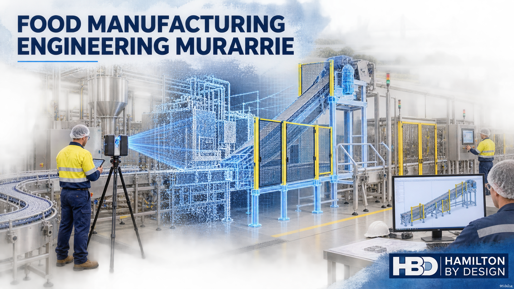
Food Manufacturing Engineering Murarrie: 3D Scanning, Plant Layouts and Production-Line Support

Hamilton By Design 3D scanning a food manufacturing production line in Murarrie, with point-cloud modelling, conveyor design and machine guarding.
Blue 3D LiDAR scanner icon on a tripod with scanning waves

Murarrie is one of Brisbaneโ€™s most strategically located industrial areas. Positioned within the Australia TradeCoast region, the suburb provides direct connections to the Gateway Motorway, Lytton Road, the Port of Brisbane Motorway, Brisbane Airport and the Port of Brisbane. This location makes Murarrie attractive to food manufacturers, packaging businesses, equipment suppliers, warehouses and high-volume distribution operations.

The value of Murarrie, however, extends beyond transport access. Its industrial properties range from established brownfield factories to modern logistics facilities. Food-processing machinery, conveyors, packaging equipment, cool rooms, storage systems and loading areas are often located within the same operational environment. When these facilities are upgraded, accurate information about existing plant conditions becomes essential.

Hamilton By Design provides mechanical engineering, 3D laser scanning, reverse engineering and drafting support for industrial facilities. By combining site capture with practical mechanical design, HBD can help Murarrie businesses plan modifications using reliable spatial information rather than incomplete drawings or assumptions.

Why Murarrie is important to Brisbane manufacturing

Murarrie is approximately 10 kilometres east of Brisbaneโ€™s central business district, but it functions as part of a much larger port, airport and industrial network. From Murarrie, businesses can access metropolitan customers, interstate transport corridors and international freight connections without operating from the CBD.

The local industrial mix includes food ingredients, packaged consumer products, packaging equipment, postal distribution, air-conditioning products, construction materials, paper and industrial fabrication. Modern developments such as Gateway@Murarrie are occupied by organisations including PepsiCo, Australia Post and Daikin, while older sections of the suburb retain manufacturing and process-industry characteristics.

This combination creates a distinctive engineering environment. A project may involve a contemporary distribution centre with automated handling equipment or an older factory in which machinery, pipework and access systems have been modified repeatedly. In both cases, the engineering team needs to understand what is physically present before changing the layout.

The challenge of modifying an operating food factory

Production facilities rarely remain exactly as originally designed. Machines are replaced, conveyors are extended, guarding is altered and services are rerouted. Small changes accumulate until the available drawings no longer match the plant.

In food manufacturing, these discrepancies can affect more than equipment fit. A proposed support, guard or conveyor modification may influence washdown access, drainage, inspection, pest control, maintenance or separation between production activities. The design must account for both the machinery and the way people operate, clean and maintain it.

Traditional tape measurements can be suitable for an isolated component, but they become inefficient in congested production areas. Important relationships between columns, platforms, services, machinery and access routes can easily be missed. Hamilton By Designโ€™s 3D laser scanning services provide a more complete record of these conditions.

A registered point cloud can capture machinery envelopes, conveyor elevations, structural obstructions, floor levels, pipework and surrounding access. The resulting dataset becomes a measurable digital reference for design reviews, relocation studies and future modifications.

From factory scan to practical engineering outcome

The value of laser scanning depends on how the information is used. A point cloud alone does not resolve a production problem; it must be interpreted by people who understand machinery, fabrication and installation.

HBD combines reality capture with 3D scanning engineering in Brisbane. The typical workflow is to scan the relevant area, register and verify the point cloud, model the required assets, develop the proposed modification and produce drawings for review or manufacture.

This integrated process can support:

  • Production-line and packaging-equipment layouts
  • Machine relocation planning
  • Conveyor extensions and transitions
  • Access-platform and guarding modifications
  • Equipment support frames and mounting arrangements
  • Clash detection around existing plant and services
  • Demolition and installation drawings
  • As-built documentation following completion

Because the existing and proposed arrangements can be reviewed in the same 3D environment, project teams can identify spatial conflicts before equipment is disconnected or steelwork is fabricated.

Production-line and packaging-equipment scanning

Packaging lines frequently combine equipment supplied by several manufacturers. Fillers, sealers, labellers, metal detectors, checkweighers, robotic cells, case packers and palletising systems may all have different interface requirements. Their successful integration depends on accurate product-transfer heights, machine clearances and maintenance access.

Scanning can document these relationships without reducing the entire factory to an unnecessarily detailed model. HBD can model the areas and interfaces relevant to the project while retaining the wider point cloud as context. This targeted approach makes the engineering model useful while controlling modelling time and cost.

The retained data can also support future projects. Factory point clouds, packaging-machine models, equipment interfaces, conveyor arrangements and approved CAD assemblies provide a stronger basis for later upgrades than a collection of unrelated field measurements.

Machine relocation and factory-layout planning

Relocating machinery is not simply a matter of placing its footprint on a floor plan. The design team must consider the route into the building, lifting requirements, operator positions, doors and guards, product flow, cleaning access and the space needed to remove components during maintenance.

HBD can develop alternative layouts using scan-based information and SolidWorks 3D modelling services. A relocation study may include:

  • Existing and proposed equipment positions
  • Infeed and discharge interfaces
  • Operator and maintenance envelopes
  • Forklift or crane access
  • Service connection locations
  • Floor penetrations and mounting points
  • Interaction with pedestrian routes
  • Clearances from building elements and surrounding machines

Reviewing these matters digitally can reduce the likelihood of discovering an obstruction during a shutdown, when both time and workable alternatives are limited.

Conveyor, guarding and access modifications

Conveyors are essential to food and packaging operations, but their transfers, drives, rollers and nip points can introduce significant hazards. Modifications should consider production performance and safe access throughout the machinery lifecycle, including cleaning, product clearing, changeovers, fault finding and maintenance.

Hamilton By Design can assist with conveyor arrangements, transition pieces, support frames, guards, covers and access layouts as part of its mechanical engineering consulting services.

Relevant project references may include:

  • AS/NZS 4024 Safety of Machinery series
  • AS 1657 for fixed platforms, walkways, stairs and ladders
  • AS 4991 for lifting devices
  • AS 3990 for mechanical equipment steelwork
  • AS 4041 for pressure piping, where applicable
  • AS 1210 for pressure vessels, where applicable

The applicable standards must be established for each project according to the equipment, hazards, site requirements and contractual scope. Electrical design, specialist hygiene advice, structural certification and professional engineering services requiring Queensland registration should be provided or reviewed by appropriately qualified practitioners.

Reverse engineering obsolete or undocumented components

Production machinery may remain operational long after original suppliers stop supporting it. Replacement parts might have long lead times, incomplete drawings or no reliable identification. In other cases, a locally modified component may never have been documented.

HBDโ€™s reverse engineering and 3D scanning workflow can assist with selected components such as:

  • Guards and covers
  • Brackets and support frames
  • Shafts and hubs
  • Machine interfaces
  • Conveyor components
  • Change-parts
  • Chutes and transition pieces
  • Pump or motor mounting arrangements

Depending on the component and required accuracy, the work may use LiDAR scanning, metrology scanning, conventional measurement or a combination of methods.

The output can include a 3D manufacturing model, detailed drawing, DXF profile or neutral CAD format. Material, tolerances, wear, surface condition and the componentโ€™s function must also be considered. Copying worn geometry without engineering interpretation may simply reproduce an existing problem.

Fabrication and mechanical drafting for plant upgrades

Clear documentation connects the engineering concept with the people who fabricate and install it. HBDโ€™s manufacturing and production services can support the preparation of:

  • General arrangement drawings
  • Equipment and conveyor layouts
  • Fabrication drawings
  • Plate developments and DXF profiles
  • Guards and removable covers
  • Support-frame details
  • Installation and demolition drawings
  • Equipment-interface drawings
  • Final as-built records

Mechanical drawings may be prepared with reference to the AS 1100 technical-drawing series and the standards applicable to the asset being documented.

HBD can provide mechanical and structural drafting. Structural assessment and certification remain the responsibility of the nominated structural engineer.

Machine guarding and workplace safety

Machinery guarding should not be assessed solely according to normal production conditions. Operators and maintenance personnel may be exposed to different hazards during cleaning, clearing blockages, changing products, inspecting equipment or replacing components.

A machinery-safety review may consider:

  • Nip, shear, crush and entanglement hazards
  • Access to conveyor drives and rollers
  • Openings around existing guards
  • Removable and interlocked guards
  • Maintenance and isolation access
  • Emergency-stop visibility and accessibility
  • Falls from platforms or machinery
  • Dropped-object hazards
  • Pedestrian and forklift interaction
  • Restricted maintenance clearances

HBD can document existing arrangements, assist with mechanical risk assessments and prepare drawings for proposed guards or access modifications. A complete risk-management process should involve the plant owner, operators, maintainers and other relevant specialists.

Engineering support for logistics and material handling

Food manufacturing does not end at the production line. Raw ingredients, packaging materials, finished products and waste streams must move safely through the facility.

HBD can assist with logistics-related engineering such as:

  • Factory and warehouse scanning
  • Conveyor and pallet-transfer arrangements
  • Loading-dock layouts
  • Forklift-clearance checks
  • Machinery delivery-path studies
  • Crane and lifting-access layouts
  • Pedestrian-segregation layouts
  • Warehouse equipment clash detection
  • Shutdown delivery sequencing

Potentially relevant standards may include AS 4084 for steel storage racking, the AS 1418 and AS 2550 series for cranes, hoists and winches, AS 4991 for lifting devices and AS/NZS 4024 for machinery and conveyor safety.

Specialist traffic engineering may be required for public-road changes, formal traffic studies or particular development approvals.

Managing Murarrieโ€™s local constraints

Murarrieโ€™s location provides excellent regional access, but individual sites can still present difficult delivery routes, congested loading areas and restricted internal turning space. Equipment-relocation planning should therefore consider the complete path from the property entrance to the final installed position.

Relevant questions include:

  • Can the delivery vehicle enter and turn within the site?
  • Can the equipment pass through the nominated doorway?
  • Is there enough overhead clearance beneath awnings and services?
  • Where can a crane, forklift or mobile lifting device operate?
  • Will unloading interfere with production or emergency access?
  • Can removed machinery leave through the same route?
  • Are temporary works or staged dismantling required?

Parts of the wider Murarrie, Hemmant and Lytton industrial area may also be affected by river, creek, overland-flow or storm-tide flooding. Exposure varies from property to property. Critical equipment, controls, stored materials and business records may require site-specific flood consideration rather than a suburb-wide assumption.

HBD can document plant geometry and equipment elevations, but flood assessment, structural design and statutory certification should be undertaken by the relevant qualified and registered professionals.

Reducing shutdown and installation risk

For an operating manufacturer, lost production can exceed the cost of the design work. The purpose of scan-based engineering is therefore not simply to produce a visually impressive model. It is to improve decisions before the shutdown begins.

An effective workflow can help project teams:

  1. Confirm that new equipment will fit.
  2. Identify clashes with existing plant and services.
  3. Establish installation and removal routes.
  4. Prepare fabrication drawings before the shutdown.
  5. Coordinate contractors around a common model.
  6. Reduce unplanned cutting and rework on site.
  7. Document the final as-built arrangement.

Revision-controlled drawings and models also establish which arrangement was approved and what was ultimately installed.

HBD can retain project information such as point clouds, layouts, equipment models, guarding records, CAD assemblies and modification drawings in accordance with agreed project and confidentiality requirements. This creates a reusable engineering baseline for later maintenance, replacement and expansion work.

Frequently asked questions

What is food manufacturing engineering?

Food manufacturing engineering applies mechanical, production and safety principles to the machinery and systems used to process, move, package and store food products. It can include conveyors, packaging equipment, access systems, machine guarding, equipment supports and factory layouts. Specialist food-safety and hygienic-design advice may also be required, depending on the project.

Can a factory be scanned while production continues?

Often, yes. The scanning plan can be arranged around access restrictions, hygiene controls and production activities. Some concealed areas or machine interfaces may still require controlled access or a shutdown. The proposed scan coverage should be agreed with site personnel before mobilisation.

Does every part of the factory need to be converted into CAD?

No. The point cloud can retain the broader site context while only the machinery, structure and interfaces relevant to the project are modelled. Selective modelling usually provides a more efficient outcome than recreating every visible object.

Can HBD assist with moving a production or packaging line?

Yes. HBD can scan the existing and proposed areas, model machinery envelopes, prepare alternative layouts and document equipment interfaces. Specialist rigging, electrical, structural, food-safety and building-services input may also be required.

Can HBD assess machine guarding?

HBD can document existing guards, identify relevant mechanical hazards and develop guard or access modifications with reference to the AS/NZS 4024 series. A complete risk assessment should involve the plant owner, operators and maintenance personnel because hazards can arise during cleaning, clearing and maintenance as well as normal production.

Can HBD reverse engineer an obsolete machine component?

Potentially, yes. HBD can scan or measure suitable components and produce manufacturing CAD or detailed drawings. Before reproducing a part, its function, material, tolerances, wear and failure history should be reviewed.

What files can be supplied?

Depending on the scope, deliverables may include registered point clouds, PDF drawings, AutoCAD files, SolidWorks models, STEP, Parasolid, DXF, E57, LAS or Autodesk ReCap-compatible data. Required formats should be confirmed at the beginning of the project.

Does Hamilton By Design provide structural certification?

HBD provides mechanical engineering and structural drafting support but does not represent itself as the structural certifier. Where structural certification or Queensland professional engineering approval is required, the work should be reviewed and certified by an appropriately qualified RPEQ.

Engineering support for Murarrie manufacturers

Murarrieโ€™s concentration of production, packaging and distribution facilities creates continuing demand for accurate plant information and practical brownfield engineering.

Whether the task involves relocating a packaging machine, modifying a conveyor, documenting an existing line or reverse engineering an obsolete component, the quality of the outcome begins with understanding the real site conditions.

Hamilton By Design combines 3D scanning, mechanical design, CAD modelling and fabrication drafting within one coordinated workflow. This helps clients progress from site capture to a practical engineering outcome while maintaining clearer responsibility for the information produced.

For assistance with food manufacturing engineering in Murarrie or factory scanning elsewhere in Brisbane, contact Hamilton By Design to discuss the equipment, site constraints, intended outcome and required deliverables.


Hamilton By Design logo displayed on a blue tilted rectangle with a grey gradient background

Contact Us – Talk To Us

Name
Would you like us to arrange a phone consultation for you?
Address

Our clients:


Bulk-Handling and Process-Plant Scanning in Hemmant and Lytton

Hamilton By Design engineer using a 3D laser scanner at a bulk-handling and process plant in Hemmant and Lytton, Queensland.
Blue 3D LiDAR scanner icon on a tripod with scanning waves

Hemmant and Lytton occupy a strategically important part of Brisbaneโ€™s industrial landscape. Located near the mouth of the Brisbane River and the Port of Brisbane, the two suburbs support a concentration of fuel infrastructure, bulk-material handling, marine engineering, fabrication, warehousing and freight operations.

This is not a conventional light-industrial precinct. Many facilities contain interconnected conveyors, storage tanks, pipework, loading gantries, transfer stations, access platforms and process equipment. Some operate continuously, while others depend on tightly controlled maintenance shutdowns.

These operating conditions create a particular engineering challenge: how can an existing plant be modified when the available drawings may no longer represent what is actually installed?

Hamilton By Design supports Hemmant and Lytton facilities through engineering-led 3D laser scanning, point-cloud modelling, mechanical design and fabrication documentation. By capturing the plant as it exists, proposed modifications can be developed around real site conditions rather than assumptions carried forward from historical drawings.

An Industrial Area Shaped by the Port

Hemmant and Lytton share a close relationship with the Port of Brisbane, but each suburb has a slightly different industrial character.

Lytton contains some of the corridorโ€™s largest infrastructure-dependent operations. Its industrial landscape includes fuel refining, petroleum storage, import terminals, pipelines, loading facilities and large logistics sites. Much of this infrastructure requires specialised land, established transport connections and separation from residential development.

Hemmant has a more varied industrial profile. Transport depots and warehouses operate alongside fabrication workshops, machinery businesses and riverfront marine facilities. Its position between Brisbaneโ€™s established industrial suburbs and the port gives businesses access to the Gateway Motorway, port terminals, the Brisbane River and the wider South East Queensland freight network.

This combination creates opportunities for engineering work across several levelsโ€”from scanning an individual worn component to documenting a complete terminal, conveyor system or process area.

Hamilton By Designโ€™s Port of Brisbane engineering and 3D laser scanning services are particularly relevant to facilities that must integrate new mechanical equipment into complex operating sites.

Why Existing-Plant Projects Are Difficult

Brownfield engineering is rarely as simple as replacing an old item with a new version of the same component.

Industrial plants evolve over time. Platforms are extended, pipework is rerouted, supports are reinforced and equipment is repositioned. Repairs may have been completed during short shutdowns without every change being incorporated into the master drawing set.

Consequently, several versions of the plant may exist simultaneously:

  • The original design drawings.
  • Later modification drawings.
  • Maintenance sketches and site mark-ups.
  • The actual installed arrangement.
  • The operatorโ€™s practical understanding of how the plant now works.

The last two are often the most important.

A replacement chute might match an old drawing but interfere with a platform brace added years later. A pipe spool may be dimensionally correct but impossible to install because there is no access for lifting or bolting. A new guard may prevent a maintenance task from being completed safely.

Engineering-grade site capture helps identify these issues before fabrication begins.

Creating a Reliable Record with 3D Laser Scanning

Terrestrial laser scanning records millions of measured points across the visible surfaces of a facility. Once the individual scans are registered, they form a coordinated three-dimensional point cloud.

For a Hemmant or Lytton industrial site, the captured information may include:

  • Conveyors and supporting frames.
  • Transfer chutes and hoppers.
  • Storage tanks and adjacent infrastructure.
  • Pipework routes and equipment connections.
  • Structural columns, beams and bracing.
  • Platforms, stairs, ladders and handrails.
  • Pumps, motors and mechanical equipment.
  • Cable trays, ducts and visible services.
  • Access ways and maintenance clearances.
  • Fabrication and installation interfaces.

A point cloud is more than a collection of measurements. It provides spatial context. An engineer can see not only the equipment being modified but also the surrounding structures and services that could affect the design.

Hamilton By Design can retain agreed project information such as registered plant point clouds, conveyor models, pipework routes, equipment interfaces, clash reports, fabrication drawings and revision histories. This creates a useful reference for later plant changes, provided the data-retention and confidentiality arrangements are defined with the client.

Conveyor and Chute Engineering

Conveyors and transfer points are critical parts of many terminals and process plants. They are also common sources of wear, spillage, dust, blockages and unplanned downtime.

A chute may appear straightforward, but its performance depends on several interacting variables:

  • Material type and bulk density.
  • Particle size and moisture content.
  • Belt width and speed.
  • Feed direction and discharge trajectory.
  • Impact angle and wear pattern.
  • Available transfer height.
  • Liner arrangement.
  • Maintenance access.
  • Surrounding plant geometry.

Changing production rates or material characteristics can expose weaknesses in a chute that previously operated acceptably. Increased moisture can promote build-up, while higher throughput can increase impact loads, dust generation and liner wear.

Hamilton By Design provides chute design and materials-handling engineering for existing industrial facilities. This may include scanning the transfer station, modelling the relevant interfaces, developing a revised arrangement and preparing fabrication-ready documentation.

Potential deliverables include general arrangements, plate details, liner drawings, support-frame drawings, bills of materials and CAD models for fabrication or client review.

Mechanical Design for Brownfield Modifications

An effective brownfield design must satisfy more than the immediate process requirement. It must also be practical to fabricate, transport, install, inspect and maintain.

Hamilton By Design can assist with mechanical modifications involving:

  • Conveyor and transfer-station layouts.
  • Chutes, hoppers and bins.
  • Pipework routes and equipment interfaces.
  • Pump and equipment skids.
  • Access platforms and maintenance structures.
  • Guards and machinery-safety improvements.
  • Support frames and brackets.
  • Removable sections and maintenance tooling.
  • Lifting arrangements for plant components.
  • Reverse-engineered replacement parts.

The proposed equipment can be modelled against the point cloud to identify potential clashes. Installation clearances, bolt access, welding access and component-removal paths can then be considered before drawings are issued.

HBDโ€™s broader mechanical engineering services for the Port of Brisbane support this connection between measured site information and practical industrial design.

Mechanical Drafting and Fabrication Documentation

A successful industrial modification depends on clear communication between the designer, client, fabricator and installer.

Hamilton By Design can prepare:

  • Existing-condition CAD models.
  • Concept layouts.
  • General arrangement drawings.
  • Fabrication and assembly drawings.
  • Plate and folded-component details.
  • Pipe spool drawings.
  • Platform and access drawings.
  • Installation reference dimensions.
  • Bills of materials.
  • DXF cutting profiles.
  • STEP and Parasolid models.
  • Issued-for-review, issued-for-approval and issued-for-construction packages.
  • Final as-built records.

Document control is especially important where several contractors are working on the same plant. Drawing numbers, revision status, design assumptions and approval responsibilities should be visible and traceable.

The objective is not simply to produce a drawing that looks complete. The documentation must provide enough information for the item to be manufactured, checked and installed with a clear understanding of its interfaces.

Safety, Access and Maintainability

Industrial safety cannot be added at the end of a project. It must influence the geometry of the design from the beginning.

For conveyor, chute and process-plant modifications, this may require consideration of:

  • Nip, crush, shear and entanglement hazards.
  • Access to isolation points.
  • Fixed and removable guarding.
  • Inspection-door locations.
  • Safe liner replacement.
  • Stair, ladder and platform access.
  • Handrail continuity.
  • Trip hazards and restricted walkways.
  • Lifting points and component weights.
  • Dropped-object exposure.
  • Emergency egress.
  • Access for cleaning and spill recovery.

The AS/NZS 4024 series may apply to machinery safety and risk reduction. AS 1657 is commonly relevant to fixed platforms, walkways, stairways and ladders, while AS 4991 may apply to purpose-designed lifting devices.

Other standards may apply depending on the project, including AS 3990 for mechanical-equipment steelwork, AS 4041 for pressure piping, AS 1210 for pressure vessels, AS 4100 for steel structures and AS 1940 for flammable and combustible liquids.

The applicable standards and required professional responsibilities should be established at the start of each project. Hamilton By Design provides mechanical engineering and drafting services. Structural, civil, electrical, hazardous-area, fire and process certification should be completed by appropriately qualified specialists where required.

The Five Recurring Problems in Hemmant and Lytton Projects

1. Drawings do not match the plant

Outdated or incomplete drawings can cause incorrect interface dimensions, fabrication errors and unexpected site modifications. A current point cloud establishes a measurable record of visible site conditions.

2. The work area is congested

Pipework, steelwork, electrical services and access structures often occupy the same limited space. Three-dimensional coordination helps expose clashes that may not be apparent in a two-dimensional drawing.

3. Shutdown time is limited

Unexpected cutting, drilling or rework can consume a large portion of a shutdown window. Pre-shutdown scanning and installation planning help reduce avoidable site work.

4. Ageing equipment has changed shape

Wear, corrosion, impact and previous repairs can cause the installed component to differ from its original design. Scanning and reverse engineering can help document the current interfaces before replacement equipment is manufactured.

5. The design fits but cannot be maintained

A component may perform mechanically while creating poor inspection, cleaning or removal access. Maintenance activities must be considered alongside the operating function.

Engineering Support for Logistics and Terminal Operations

Not every project in Hemmant or Lytton is part of a process plant. Warehouses, freight depots and loading facilities also need accurate layouts for new equipment and operational changes.

Hamilton By Design can assist logistics and terminal operators with:

  • Warehouse and hardstand scanning.
  • Loading-area layouts.
  • Conveyor and automation interfaces.
  • Equipment clearances.
  • Maintenance-access zones.
  • Crane and lifting access.
  • Guarding arrangements.
  • Equipment-removal studies.
  • Clash detection.
  • Staged installation planning.
  • Updated as-built layouts.

Vehicle swept paths, pavement design, drainage and formal traffic engineering should be referred to the appropriate civil or traffic specialist where they sit outside the mechanical scope.

From Site Capture to Fabrication

A typical HBD workflow begins by defining the engineering outcome rather than scanning an arbitrary area.

The process may include:

  1. Reviewing the operational problem, available drawings and required deliverables.
  2. Planning the scan around design interfaces, access restrictions and site rules.
  3. Capturing the relevant equipment and surrounding work envelope.
  4. Registering and quality-checking the point cloud.
  5. Modelling the existing plant to the level needed for the project.
  6. Developing one or more modification concepts.
  7. Reviewing clashes, access and installation constraints.
  8. Preparing approval, fabrication and installation documentation.
  9. Recording approved revisions and final as-built information.

This connected approach reduces the information gap that can occur when one party scans the plant, another produces the model and a third completes the design.

Hamilton By Designโ€™s experience with bulk-material handling, ROM systems, conveyors and transfer engineering is transferable to port, terminal and process-plant applications where fit, reliability and maintainability are critical.

Frequently Asked Questions

Can a process plant be scanned while it remains operational?

In many cases, yes. The scan plan must account for site access, exclusion zones, moving equipment, hazardous areas and operational controls. Some critical interfaces may still require access during an isolation or shutdown.

What can be delivered from a plant scan?

Deliverables can include registered point clouds in formats such as E57, RCP, RCS or LAS, along with selected CAD models, plans, sections, general arrangements, fabrication drawings and clash-review information. The appropriate deliverable depends on the intended engineering outcome.

Can HBD work from point-cloud data captured by another company?

Potentially, yes. The supplied dataset should first be reviewed for registration quality, point density, coverage and visibility of the required interfaces. Missing flange faces, pipe centrelines, bolt holes or concealed areas may limit the achievable result.

Does laser scanning capture internal pipe or vessel conditions?

No. Terrestrial laser scanning primarily records visible external surfaces. Internal condition, wall thickness, corrosion and material integrity normally require specialist inspection methods such as ultrasonic testing, internal inspection or non-destructive examination.

Can HBD design a replacement chute from the scan?

Yes, subject to an agreed scope and sufficient operating information. A scan establishes existing geometry, but chute design may also require material properties, throughput, belt speed, moisture content, wear history and operator feedback.

Does HBD provide structural certification?

Hamilton By Design provides mechanical engineering and structural drafting support but is not offering structural certification through this service. Where structural verification or certification is required, the work should be completed or reviewed by an appropriately qualified structural engineer.

Can scanning help with shutdown planning?

Yes. A point cloud can support prefabrication, clash detection, access reviews, crane planning and installation sequencing. It does not eliminate every shutdown risk, but it can significantly reduce uncertainty about visible site geometry.

How accurate is an industrial point cloud?

Accuracy depends on the scanner, range, target arrangement, registration method, environmental conditions and visibility. The required accuracy should be discussed before scanning so that the capture method is suitable for the intended design or verification task.

Can HBD retain the project data for future modifications?

Yes, subject to the agreed commercial, confidentiality and retention arrangements. Records may include registered point clouds, equipment models, interface information, drawings and modification histories.

Engineering Existing Plant with Greater Confidence

Hemmant and Lytton are shaped by infrastructure that must remain safe, reliable and productive. Their fuel terminals, process facilities, conveyors, warehouses, marine workshops and freight operations are expensive to interrupt and difficult to modify using incomplete site information.

Engineering-led 3D scanning gives project teams a stronger starting point. When accurate site capture is combined with mechanical design, fabrication documentation and practical installation planning, brownfield modifications can be developed with a clearer understanding of the plant they must fit.

Hamilton By Design can assist clients in Hemmant, Lytton and the wider Port of Brisbane corridor with process-plant scanning, bulk-handling design, point-cloud modelling, reverse engineering, mechanical drafting and brownfield upgrade documentation.

To discuss a conveyor, chute, pipework, terminal or existing-plant project, contact Hamilton By Design with the site location, a short description of the problem, available drawings or photographs, required deliverables and any planned shutdown dates.


Hamilton By Design logo displayed on a blue tilted rectangle with a grey gradient background

Contact Us – Talk To Us

Name
Would you like us to arrange a phone consultation for you?
Address

Our clients: