


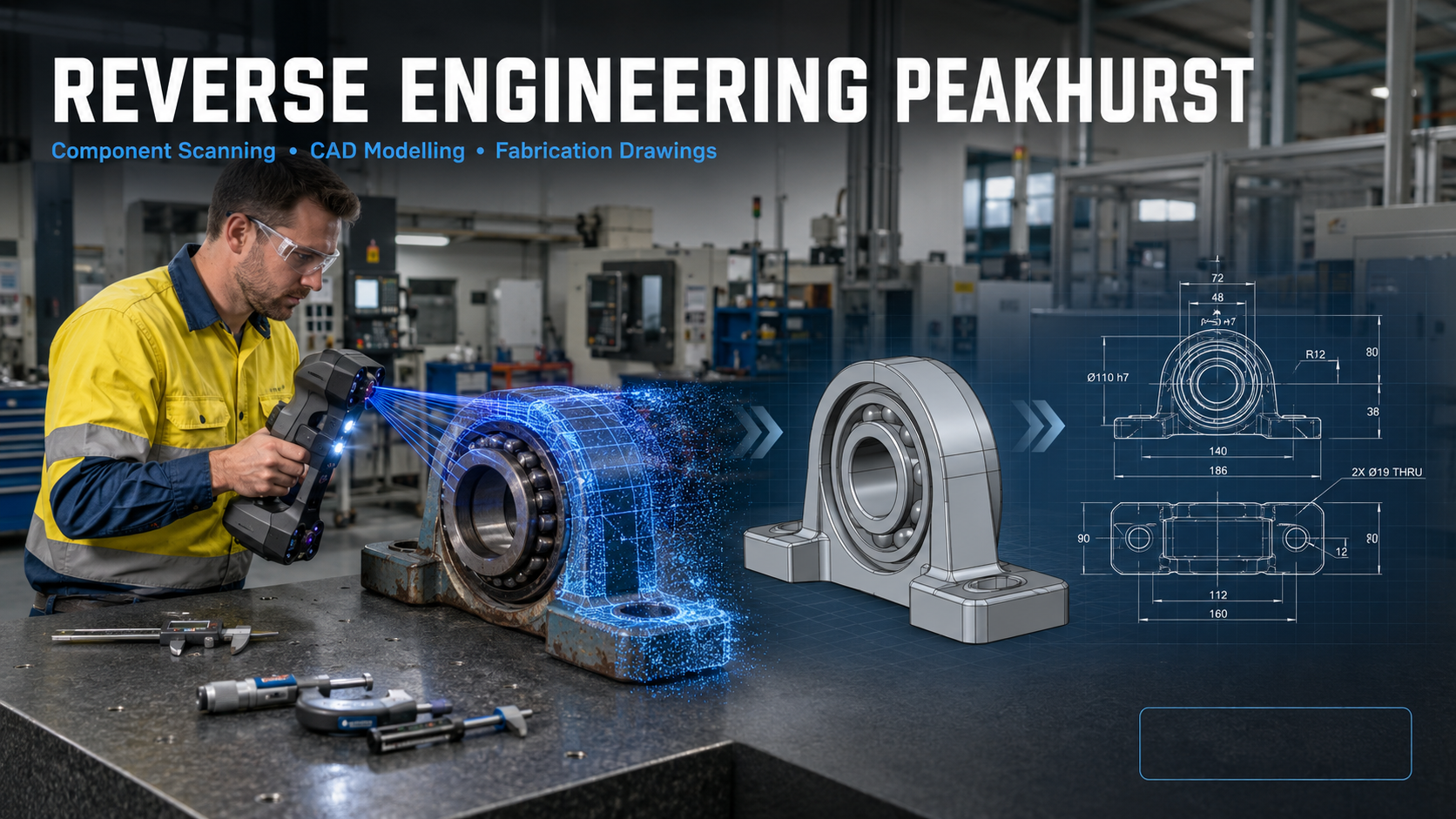
Reverse Engineering Peakhurst: Component Scanning, CAD Modelling and Fabrication Drawings

Peakhurst is an established industrial area in southern Sydney with a practical concentration of precision manufacturing, metalwork, machinery services, commercial joinery, industrial equipment, fabrication and specialist workshops. These activities depend on accurate dimensions, controlled technical information and machinery that can be maintained or modified without unnecessary production delays.
However, many industrial businesses operate equipment for which the original engineering information is incomplete, outdated or no longer available. A machine may have been modified repeatedly during its operating life. A component may be worn, damaged or commercially obsolete. An overseas manufacturer may no longer support the equipment, while a replacement part may have an unacceptable cost or lead time.
Hamilton By Design provides reverse engineering in Peakhurst to help businesses convert existing components and machinery into practical engineering information. This may involve component scanning, physical measurement, 3D CAD modelling, mechanical drafting, fabrication drawings, machinery modifications and the controlled retention of project records.
The objective is not simply to produce a digital copy of an object. Engineering-led reverse engineering considers what the component does, how it interacts with adjoining parts, how it may have worn and what information a manufacturer needs to reproduce or improve it successfully.
Why Peakhurst Is Well Suited to Reverse Engineering
Peakhurst’s industrial character includes precision CNC machining, CAD/CAM operations, welding, steel fabrication, dimensional inspection, prototyping and joinery manufacturing. This creates a useful relationship between businesses that need engineering information and workshops capable of manufacturing from models and drawings.
Publicly described local capabilities include multi-axis machining, coordinate measurement, rapid prototyping, steelwork, welding and commercial joinery. These operations demonstrate that Peakhurst is not simply a warehouse area. It contains technically capable manufacturers and workshops that rely on accurate digital models and controlled production information.
Reverse engineering can bridge the gap between an existing physical asset and these manufacturing capabilities. Hamilton By Design’s reverse engineering and Scan-to-CAD studies provide a structured method for capturing existing geometry and converting it into engineering models and drawings.
This can support local manufacture, equipment repair, product improvement, machinery modification or the creation of a reliable asset record.
What Is Reverse Engineering?
Reverse engineering is the systematic process of examining an existing component, machine or assembly to recreate the technical information required to understand, reproduce, modify or replace it.
The starting point may be:
- An existing component without a drawing
- A worn or damaged machine part
- An obsolete replacement item
- A fabricated frame or assembly
- A machine that has been modified on site
- An imported system with limited documentation
- A sample provided to a machining or fabrication workshop
- An incomplete or unreliable drawing set
The required outcome might be a 3D CAD part, mechanical assembly, manufacturing drawing, fabrication package, machinery layout or dimensional comparison report.
Hamilton By Design’s work on reverse engineering industrial equipment using 3D scanning combines captured geometry with engineering judgement. This distinction matters because scan data alone does not define the original design intent.
Five Common Problems Facing Peakhurst Businesses
1. Missing or outdated machinery drawings
Industrial machinery is frequently modified during maintenance, breakdown repairs or production upgrades. New brackets may be added, guards replaced and components altered without the engineering drawings being updated.
Over time, the available documentation becomes progressively less reliable. A future modification may then be designed around a drawing that no longer represents the physical machine.
Scanning and measuring the installed asset provides a new as-built reference. The captured data can be used to produce a controlled CAD model and updated drawings reflecting the equipment’s current arrangement.
2. Obsolete replacement components
A replacement component may no longer be commercially available. The original manufacturer may have ceased trading, stopped supporting the machine or relocated its spare-parts operation overseas.
Reverse engineering can establish the geometry required to investigate repair or local manufacture. This may reduce dependence on unsupported equipment suppliers and provide the asset owner with a reusable engineering record.
However, geometry is only one part of the problem. A scan cannot independently determine:
- Material grade
- Heat treatment
- Surface hardness
- Internal geometry
- Original design loads
- Surface finish
- Manufacturing tolerance
- Fatigue history
- Allowance for wear or corrosion
These factors must be established through inspection, research, testing, calculations and engineering judgement before a replacement part is released for production.
3. Unclear manufacturing requirements
A highly detailed mesh may look impressive on a computer screen but still be unsuitable for manufacturing. A machine shop needs more than an external surface.
Manufacturing information may need to define:
- Nominal dimensions
- Fits and clearances
- Geometric tolerances
- Threads and fasteners
- Bearing and seal seats
- Materials
- Surface finishes
- Weld requirements
- Heat treatment
- Inspection dimensions
- Assembly relationships
Hamilton By Design provides 3D CAD modelling in Sydney to convert captured geometry into practical parts and assemblies. The aim is to create a structured engineering model rather than leaving the client with an uncontrolled mesh.
4. Machinery modification and installation risk
A replacement part may fit the component in isolation but interfere with the complete machine. Similarly, a new guard, frame or support may clash with electrical services, access routes, adjoining equipment or maintenance requirements.
Scanning the component together with the surrounding machinery helps identify these physical interfaces. For broader modifications, 3D scanning services in Sydney can capture the machine, workshop and nearby infrastructure as a coordinated existing-condition record.
This can reduce the risk of discovering errors during installation, when modification is often most expensive and disruptive.
5. Fragmented engineering data
Machinery records may be spread across old drawing cabinets, individual computers, maintenance systems and external contractors. Files may use inconsistent naming conventions or contain no clear revision history.
A reverse engineering project provides an opportunity to create a controlled asset record containing the approved component geometry, CAD models, drawings, inspection information, photographs, assumptions and revision status.
A Practical Reverse Engineering Workflow
Step 1: Define the purpose
The first question is not “Which scanner should be used?” It is “What engineering decision must the information support?”
A model created only for visualisation will have different requirements from a component intended for precision CNC machining. The project scope should define:
- The component or machine being investigated
- Its operating function
- The reason for reverse engineering
- Critical interfaces
- Required accuracy
- Deliverable formats
- Proposed manufacturing process
- Required design or safety reviews
This early definition determines the appropriate measurement tools and level of modelling detail.
Step 2: Review existing information
Existing drawings, manuals, photographs, samples and maintenance records should be collected. Even an outdated drawing may contain useful information about nominal dimensions, materials or the original design intent.
Operators and maintenance personnel can also provide valuable evidence. They may know where the equipment regularly fails, which components have been altered and what access problems affect servicing.
Step 3: Inspect the component or machine
The physical asset should be inspected before capture. The review should identify:
- Wear and deformation
- Corrosion
- Missing features
- Repairs and weld build-up
- Inaccessible surfaces
- Moving interfaces
- Critical datums
- Mating components
- Areas requiring detailed measurement
A worn component should not necessarily be recreated at its measured worn size. Bearings, seals, shafts, housings and standard fits may help establish the intended nominal dimensions.
Step 4: Select the correct measurement tools
Different capture tools suit different applications.
A handheld laser or structured-light scanner can be effective for castings, moulded parts, guards, housings and complex surfaces. Terrestrial LiDAR is better suited to complete machines, production areas and workshop layouts.
Critical features may also require calipers, micrometers, bore gauges, thread gauges, height gauges or specialist coordinate-measuring equipment.
Hamilton By Design’s 3D laser scanning and CAD modelling services integrate real-world capture with engineering modelling. The selected method should always reflect the required tolerance and intended use of the data.
Step 5: Process and verify the data
Captured scans must be processed, aligned and checked. Temporary objects, reflections and inaccessible areas may create incomplete or misleading geometry.
Reference measurements should be used to verify scale and alignment. For precision components, the expected measurement uncertainty must be compared with the required manufacturing tolerance.
A scan that is suitable for documenting a machine frame may not be sufficiently accurate for a bearing seat. Additional metrology may be required where tight fits or critical inspection requirements are involved.
Step 6: Create the engineering model
The point cloud or mesh becomes a reference for building the CAD model. Depending on the project, the model may contain:
- Machined features
- Sheet-metal parts
- Weldments
- Shafts and rollers
- Brackets
- Housings
- Guards
- Machine frames
- Mechanical assemblies
- Installation interfaces
Hamilton By Design’s SolidWorks drafting services can support parametric component models, assemblies and manufacturing documentation.
A parametric model is generally more useful than an uncontrolled scan mesh because features can be reviewed, dimensioned and modified as the design develops.
Step 7: Review function and manufacture
The reconstructed model should be reviewed against the component’s function and proposed manufacturing process.
This may include consideration of:
- Material selection
- Fits and tolerances
- Load paths
- Wear surfaces
- Alignment
- Fasteners
- Welded connections
- Tool access
- Machining sequence
- Assembly and disassembly
- Inspection requirements
- Maintenance access
Where loads, materials and boundary conditions are sufficiently defined, engineering calculations or finite element analysis may be used to assess a design or compare alternatives.
Step 8: Prepare drawings
A complete drawing communicates the information that cannot be inferred reliably from the 3D model.
Hamilton By Design’s Australian design and drafting services can provide:
- Component drawings
- Manufacturing drawings
- Fabrication drawings
- General arrangements
- Assembly drawings
- Exploded views
- Bills of materials
- Sheet-metal flat patterns
- DXF cutting profiles
- Installation drawings
- Controlled PDF drawing sets
- Agreed CAD exchange formats
Drawings should use appropriate dimensions, tolerances, materials, weld symbols, finishes, notes and revision controls.
Machinery Modifications in Peakhurst
Reverse engineering is not limited to copying parts. It can also support machinery upgrades and modifications.
Hamilton By Design’s mechanical engineering services in Sydney may assist with:
- Modified machine frames
- Replacement brackets and supports
- Conveyor changes
- Equipment interfaces
- Guards and enclosures
- Platforms and maintenance access
- Chutes and transfer arrangements
- Workshop equipment layouts
- Installation planning
The existing equipment can be scanned before the modification is designed. The proposed design can then be overlaid against the captured geometry to assess clearances and potential clashes.
Mechanical Drafting and Australian Standards
The relevant Australian Standards depend on the machine, component, material and application. Standards should be selected for the actual project rather than applied as a generic list.
Potential references include:
- AS 1100 series for technical drawing conventions
- AS/NZS 4024 series for machinery safety
- AS/NZS 4024.3610 for conveyors
- AS 1657 for fixed platforms, walkways, stairs and ladders
- AS 4100 for steel structures
- AS/NZS 1554 for structural steel welding
- AS 4991 for lifting devices
- AS 4084 for steel storage racking
- AS ISO 31000 for risk-management principles
- AS/NZS 3000 where electrical installation requirements are relevant
Pressure equipment may also require consideration of AS/NZS 1200, AS 1210 or AS 4041, depending on the asset and scope.
Producing a drawing with reference to an Australian Standard does not automatically certify the machine, structure or component. Design verification, certification and statutory approval must be specifically included in the scope and undertaken by appropriately qualified or licensed people.
Machinery Safety and Risk Management
Machinery modification can introduce new hazards or alter existing controls. Changes to guards, frames, access points or operating sequences should therefore be reviewed systematically.
Common workshop and machinery hazards include:
- Rotating shafts and couplings
- Conveyor nip points
- Crushing and shearing zones
- Entanglement
- Unexpected movement
- Stored pneumatic, hydraulic or mechanical energy
- Ejected components
- Hot surfaces
- Inadequate maintenance access
- Unsafe platforms and stairs
- Interaction between pedestrians and mobile equipment
Hamilton By Design provides machine guarding design and engineering for industrial machinery and materials-handling systems. Assistance may include machinery capture, hazard reviews, guard concepts, access arrangements and fabrication drawings.
Risk controls should follow the hierarchy of controls. Hazards should be eliminated where reasonably practicable before relying on isolation, engineering controls, administrative procedures or personal protective equipment.
Supporting Logistics and Workshop Layouts
Peakhurst also supports warehousing, distribution and workshop operations where equipment layout influences productivity and safety.
Engineering and scanning services can assist with:
- Workshop machinery layouts
- Equipment relocation
- Conveyor arrangements
- Racking interfaces
- Loading and unloading zones
- Forklift and pedestrian separation
- Maintenance clearances
- Palletising equipment
- Special-purpose lifting devices
- Installation drawings
- Clash detection
- As-built documentation
These projects may involve AS 4084 for steel storage racking, AS/NZS 4024.3610 for conveyors, AS 1657 for fixed access systems and AS 4991 for lifting devices.
Retaining Component and Machinery Data
The lasting value of reverse engineering depends on how the information is retained.
Subject to the agreed project arrangements, Hamilton By Design can retain:
- Component geometry
- Point clouds and meshes
- CAD parts and assemblies
- Machinery records
- Manufacturing and fabrication drawings
- Dimensional inspection information
- Photographs
- Design assumptions
- Drawing revisions
- Superseded files
This information can support later repairs, replacement parts, safety improvements and machinery modifications without repeating the complete capture process.
Frequently Asked Questions
What types of components can be reverse engineered?
Potential components include shafts, rollers, brackets, housings, guards, fabricated frames, machine parts, castings, sheet-metal items and mechanical assemblies. Suitability depends on the component’s size, accessibility, condition and required manufacturing accuracy.
Can a component be manufactured directly from a scan?
Not usually without further engineering work. A scan provides accessible surface geometry, but manufacturing may also require nominal dimensions, tolerances, materials, heat treatment, surface finish and inspection requirements.
What if the component is worn or damaged?
The measured geometry can be assessed against mating components, bearings, seals, standard sizes and any available historical information. The intended nominal geometry may then be reconstructed rather than simply copying the wear.
Which scanner is best for component reverse engineering?
The appropriate scanner depends on component size, geometry, surface condition and required tolerance. Handheld scanners are often suitable for detailed components, while terrestrial LiDAR is generally better for complete machinery and workshop layouts.
Can Hamilton By Design prepare SolidWorks models?
Yes. Scan and measurement data can be used to develop SolidWorks parts, assemblies, sheet-metal models and weldments. STEP, DWG, DXF, PDF and other agreed deliverables may also be provided.
Can the drawings be used by a local Peakhurst machine shop?
The drawings can be prepared to communicate the agreed manufacturing requirements. The selected machine shop should review the package and confirm its process, tooling, tolerances, inspection methods and production capability before manufacture.
Can reverse engineering improve an existing component?
Yes. The existing component can be used as the starting point for reviewing wear, access, manufacturability or recurring failure. Any design change should be assessed against the component’s function, loads, interfaces and safety requirements.
Can machinery and the surrounding workshop be scanned together?
Yes. Capturing the wider area can help assess equipment access, clearances, structural interfaces and potential clashes during machinery modification or relocation.
Can reverse engineering assist with machinery safety?
Yes. Machinery capture can help identify exposed moving parts, unsafe access and inadequate guarding. Hamilton By Design can develop guarding and modification concepts, subject to the agreed engineering and verification scope.
How long does a reverse engineering project take?
The timeframe depends on component complexity, site access, required accuracy, available historical information and the level of manufacturing documentation required. A simple component may be completed relatively quickly, while a complete machine may require staged capture, modelling and review.
Can Hamilton By Design retain the engineering files?
Yes, subject to the agreed commercial, confidentiality and data-management arrangements. Retention can include component geometry, CAD models, drawings and dimensional records.
Engineering Support for Peakhurst Manufacturers
Reverse engineering provides Peakhurst manufacturers, fabricators and workshop operators with a structured way to recover missing engineering information.
When component scanning is combined with physical measurement, CAD modelling, mechanical design and controlled drafting, an existing asset can become a practical engineering resource. The resulting information may support component replacement, machinery modification, local manufacture, safety improvements or future maintenance.
Hamilton By Design provides reverse engineering, component scanning, mechanical drafting, fabrication drawings and machinery-modification support for businesses in Peakhurst and across Sydney.
Whether the requirement involves a single machine part or a complete workshop installation, the process begins by defining the operational problem, the required accuracy and the engineering deliverables needed to solve it.

Contact Us – Talk To Us
Our clients:
























