Sydney Manufacturing Upgrades: Why 3D LiDAR Data Should Come Before Production Changes

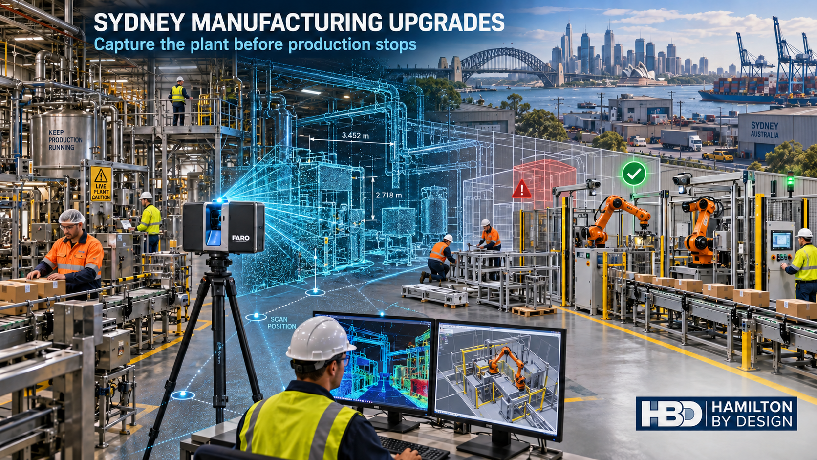
3D LiDAR scanning of a Sydney manufacturing facility with robotic production cells, point-cloud data and the Hamilton By Design logo.
Blue 3D LiDAR scanner icon on a tripod with scanning waves

Australian manufacturing is entering a period of accelerated technological and operational change. Automation, artificial intelligence, mobile robotics and data-driven production systems are creating opportunities for Sydney manufacturers to improve productivity, production quality and competitiveness.

However, introducing new technology into an existing factory is rarely as simple as purchasing a machine and installing it.

New production equipment must fit within an established operating environment containing conveyors, services, access platforms, structural elements, pipework, electrical infrastructure and other machinery. If the existing factory is not accurately documented before an upgrade begins, installation problems can lead to delays, rework and extended production shutdowns.

For manufacturers, lost time during an upgrade means lost production. Depending on the facility, even a few additional hours of downtime can affect output targets, labour utilisation, customer deliveries and revenue.

The September 2026 edition of Manufacturersโ€™ Monthly included an article titled โ€œThe trends shaping Australian manufacturing.โ€ The article discussed the growing importance of automation, artificial intelligence, mobile robotics and data-driven production systems within Australian industry.

It also made an important observation: successful automation does not depend solely on purchasing technology. Manufacturers need reliable systems supported by engineering capability, maintenance, service and long-term relationships.

This is particularly relevant to brownfield manufacturing facilities across Sydney.

Many factories were constructed or expanded over several decades. Machines may have been relocated, production lines modified, services rerouted and safety systems upgraded without every alteration being incorporated into the original drawings.

Consequently, the available drawings may no longer represent the factory as it exists today.

Before a manufacturer invests in new automation or production equipment, it is important to establish a reliable record of the existing facility. Three-dimensional LiDAR scanning provides a practical way to collect that information.

The industrial diversity of Sydney

Sydneyโ€™s manufacturing sector is not concentrated in a single precinct. It extends across Western Sydney, South-West Sydney, the Parramatta industrial corridor, the inner south, the Sutherland Shire and the Northern Beaches.

These areas contain food and beverage manufacturers, pharmaceutical businesses, metal fabricators, plastics manufacturers, logistics facilities, engineering workshops, chemical-processing operations and businesses supplying construction, transport, defence and infrastructure projects.

The requirements of each facility are different, but many face a common challenge: upgrading an operating factory while minimising disruption to production.

A manufacturer in Wetherill Park may be rearranging machinery to accommodate a new production cell. A business requiring reverse engineering in Smithfield may need to reproduce an obsolete component. A facility considering 3D laser scanning in Ingleburn or Minto may be planning a conveyor extension or automation project.

In each case, reliable existing-condition information provides the foundation for better planning.

What is 3D LiDAR scanning?

A terrestrial 3D LiDAR scanner uses laser measurements to capture the visible surfaces of a factory, production line or industrial facility. Each scan records millions of measured points, collectively forming a three-dimensional point cloud.

The resulting dataset can capture:

  • existing production equipment;
  • conveyors and transfer points;
  • pipework and ducting;
  • access platforms, stairs and handrails;
  • columns, beams and visible building geometry;
  • floor levels and penetrations;
  • overhead services;
  • electrical cabinets;
  • maintenance access areas;
  • machine interfaces; and
  • restricted installation spaces.

Multiple scan positions can be registered together to create a coordinated digital record of the required work area.

The point cloud can then support equipment layouts, clash reviews, three-dimensional CAD models, general-arrangement drawings and installation planning.

This approach is applicable to established facilities such as those requiring industrial 3D laser scanning in Silverwater and to machinery-focused projects requiring reverse engineering in Seven Hills.

Why scanning should happen before upgrade design

A production upgrade normally begins with a desired outcome. The manufacturer may want to:

  • increase production capacity;
  • replace unreliable equipment;
  • reduce manual handling;
  • introduce robotics;
  • improve guarding;
  • modify product flow;
  • lower energy consumption;
  • improve cleaning access;
  • introduce condition monitoring; or
  • reconfigure the line for a different product.

The design team must then determine how the proposed equipment will interact with the existing facility.

When that assessment is based on outdated drawings or isolated manual measurements, important constraints may remain undiscovered until fabrication or installation.

Typical problems include:

  • equipment that does not fit through the proposed installation route;
  • conveyors that do not align with existing machinery;
  • pipework or ducting occupying the required space;
  • columns conflicting with new equipment;
  • insufficient maintenance clearance;
  • access platforms obstructing robotic movement;
  • floor penetrations in unsuitable locations;
  • incorrect equipment-interface heights;
  • inaccurate machine centre lines; and
  • guarding that cannot be installed as designed.

A detailed LiDAR survey does not remove every project risk, but it substantially improves the quality of the existing-condition information available to designers, fabricators and installers.

Businesses considering 3D laser scanning in Revesby, factory scanning in Chipping Norton or 3D laser scanning in Prestons can use the resulting point cloud to assess proposed equipment against measured site geometry before a shutdown begins.

Lost upgrade time becomes lost production

Production downtime is one of the most significant risks associated with brownfield factory upgrades.

Manufacturers may schedule installation work during a weekend, planned maintenance period or annual shutdown. These windows are often tightly controlled because production must resume by a defined time.

If a dimensional error is discovered during installation, the consequences can extend beyond the cost of modifying one component. A delay can affect the entire commissioning sequence.

For example, a support frame may need to be cut and altered because it conflicts with an existing service. This can delay equipment installation, guarding, electrical work, testing and commissioning. Production cannot restart until the complete system is safe and operational.

The resulting cost may include:

  • lost production output;
  • additional contractor hours;
  • extended crane or access-equipment hire;
  • emergency fabrication;
  • express freight;
  • delayed commissioning;
  • missed customer deliveries;
  • idle production employees; and
  • disruption to downstream operations.

The cost of collecting accurate site data before design is generally small compared with the potential cost of an unplanned shutdown extension.

This consideration is especially important for high-throughput logistics and manufacturing facilities around Eastern Creek, port-related and process operations requiring industrial scanning in Botany, and manufacturers planning factory scanning in Smeaton Grange.

Moving uncertainty out of the shutdown window

The purpose of pre-upgrade scanning is not merely to produce an impressive point-cloud image. Its practical purpose is to move uncertainty away from the shutdown window and into the planning stage.

Before production stops, the project team can examine:

  • whether the new equipment will fit;
  • whether existing services must be relocated;
  • whether the proposed installation route is practical;
  • how the new equipment will connect to the existing line;
  • whether maintenance and cleaning access will remain available;
  • whether guarding can be installed;
  • where temporary equipment can be positioned; and
  • which components should be prefabricated.

Questions resolved during design are generally less expensive than problems discovered during installation.

For manufacturers using 3D laser scanning in Glendenning, reverse engineering in St Marys or 3D laser scanning in Yennora, the same principle applies: capture the existing conditions before committing to the final arrangement.

Supporting design while the production line remains operational

One of the principal advantages of 3D scanning is that much of the upgrade planning can occur while the existing production line remains operational.

Subject to site access and safety requirements, the facility can be scanned during normal production, a short maintenance window, a weekend or a planned low-activity period. The resulting point cloud provides a reference that the project team can continue using after leaving the site.

Designers can use the dataset to:

  • establish the existing production-line arrangement;
  • determine equipment footprints and interface positions;
  • examine installation and removal routes;
  • assess access for cranes, forklifts and elevated work platforms;
  • plan temporary works and equipment laydown areas;
  • identify potential spatial clashes;
  • develop preliminary equipment arrangements;
  • prepare fabrication drawings; and
  • coordinate proposed changes with the existing plant.

This allows more decisions to be made before manufacturing or installation begins.

The approach is relevant to machinery and component projects requiring reverse engineering in Milperra or reverse engineering in Condell Park, as well as facility-layout projects requiring 3D laser scanning in Villawood.

Existing drawings may not represent the existing plant

Many brownfield factories have drawing sets containing valuable information. However, the presence of drawings does not automatically mean that they accurately reflect current site conditions.

A facility may have undergone years of incremental changes, including:

  • replacement machines with different footprints;
  • locally fabricated platforms;
  • undocumented pipework;
  • revised production-line layouts;
  • temporary modifications that became permanent;
  • new electrical cabinets;
  • relocated access routes;
  • additional guarding; and
  • building alterations.

These changes can create a gap between the documented factory and the physical factory.

Scanning helps identify that gap. Existing drawings can still be used, but they can be reviewed against measured conditions rather than accepted without verification.

This can be valuable in established industrial areas such as Rydalmere, Camellia and Granville, where industrial properties may have undergone multiple changes during their operating lives.

From point cloud to installation planning

After scanning, the registered point cloud can be imported into suitable engineering and design platforms. Depending on the project requirements, the data may be used directly as a spatial reference or converted into selected CAD geometry.

Not every visible object must be modelled. The level of modelling should suit the decisions the project team needs to make.

For example:

  • a preliminary layout may require equipment envelopes and building geometry;
  • a conveyor modification may require accurate transfer points, centre lines and support locations;
  • a pipework project may require pipe centre lines, flange locations and nearby obstructions;
  • a robotic cell may require a detailed working envelope and guarding layout;
  • a replacement component may require higher-resolution scanning or direct measurement; and
  • a fabrication package may require verified interfaces and defined tolerances.

The most effective scope is based on the project outcome rather than an assumption that every captured surface must become a detailed solid model.

Manufacturers planning projects around Blacktown, Emu Plains and Penrith can use this staged approach to match the amount of modelling to the upgradeโ€™s actual requirements.

Supporting Western Sydneyโ€™s manufacturing growth

Western Sydney continues to accommodate major industrial, logistics and advanced-manufacturing activity. New development is occurring alongside older facilities that require continuing upgrades.

For established plants, the challenge is often to introduce modern production systems within buildings that were not originally designed for them. For new facilities, accurate scanning can still assist when equipment installation, services and building works have developed separately.

Hamilton By Design provides industrial scanning across Western Sydney to support the transition from existing-condition capture to engineering documentation.

Growth areas such as Marsden Park and Riverstone and the Mamre Road and Kemps Creek industrial precinct are likely to contain a combination of new facilities, expanding operations and future production changes.

Collecting and retaining accurate spatial data can help these businesses manage later modifications without repeatedly starting from incomplete information.

South and South-West Sydney manufacturing

South and South-West Sydney contain a broad range of food-production facilities, packaging operations, engineering workshops, warehouses and light-manufacturing businesses.

Plants in these areas may face restricted access, congested production floors and limited shutdown periods. These conditions increase the value of completing measurement and design work before installation begins.

Relevant local capabilities include:

Scanning may be used to document a single machine, a production cell or a larger operating area. The correct extent depends on the proposed upgrade and the equipment or services likely to be affected.

Inner-south and airport industrial areas

The industrial areas around Alexandria, Rosebery, Mascot and Botany combine older industrial buildings with newer logistics, technology, food-production and commercial facilities.

These properties can present particular upgrade challenges, including restricted delivery access, limited internal space, overhead services and buildings that have undergone multiple changes of use.

Industrial engineering support in Alexandria and Rosebery can help businesses document existing machinery and plan modifications. Similarly, industrial 3D scanning in Mascot can assist with factory layouts, equipment installation and access planning.

Where installation access is restricted, the point cloud can also help the project team investigate how equipment will be delivered, moved through the building and positioned without relying solely on assumptions made from a floor plan.

Sutherland Shire and southern industrial facilities

The Sutherland Shire contains engineering businesses, manufacturers, processing facilities and workshops serving Sydneyโ€™s construction, marine and industrial markets.

Projects may involve production machinery, pumping equipment, fabricated components, plant modifications or replacement parts.

Hamilton By Design supports this region through services including:

The same principle remains central: the quality of the upgrade decision depends partly on the quality of the information used to describe the existing plant.

Northern Sydney and Northern Beaches manufacturing

Although Western and South-West Sydney contain many of the cityโ€™s major industrial precincts, specialist manufacturers and engineering businesses also operate across Northern Sydney and the Northern Beaches.

These businesses may work from smaller, space-constrained facilities where equipment access and floor-area efficiency are critical.

Local services include:

In smaller factories, a poorly planned equipment change can consume valuable production area or restrict access to surrounding machinery. A three-dimensional survey helps assess spatial relationships before new equipment is ordered or fabricated.

Connecting the physical factory with digital manufacturing

The move toward smarter manufacturing depends on reliable information about physical assets.

Automation systems may produce large volumes of operational data, but an upgrade project still requires an accurate understanding of where equipment is located and how it interfaces with the surrounding facility.

A registered point cloud can provide the geometric foundation for a digital representation of the factory. Depending on the project requirements, the data may support:

  • scan-to-CAD modelling;
  • production-line layouts;
  • digital-twin development;
  • robotic-cell planning;
  • conveyor modifications;
  • clash detection;
  • machine-guarding reviews;
  • fabrication drawings;
  • shutdown planning; and
  • future asset-management activities.

This can be particularly valuable for manufacturers operating facilities that have grown through multiple stages of expansion.

Instead of starting each upgrade with another series of disconnected measurements, the business can retain a controlled digital record and update it as the facility changes.

Data collection must be planned around the intended outcome

Not every scanning project requires the same level of detail.

A general factory-layout survey differs from a dimensional inspection or metrology survey of a machine component. Similarly, a scan intended for equipment-placement planning may not capture every concealed service or individual fastening detail.

Before scanning begins, the manufacturer and scanning provider should agree on:

  • the purpose of the proposed upgrade;
  • the decisions the data must support;
  • the required deliverables;
  • the areas that must be captured;
  • critical equipment interfaces;
  • required measurement confidence;
  • production and access restrictions;
  • areas concealed by guarding or stored materials;
  • whether equipment will be operating during scanning;
  • required file formats; and
  • how the data will be stored for future projects.

Clear scope definition helps ensure that the collected data is suitable for the engineering decisions it will support.

Capturing machine interfacesโ€”not just the building

A factory scan should be planned with an understanding of the proposed mechanical work.

A survey that captures the overall building but misses critical equipment interfaces may not provide enough information for fabrication or installation.

Depending on the project, important details may include:

  • machine centre lines;
  • mounting surfaces;
  • conveyor elevations;
  • shaft positions;
  • flange faces;
  • bolt-hole locations and clocking;
  • pipe centre lines;
  • connection points;
  • guarding interfaces;
  • access requirements; and
  • maintenance-removal paths.

Plant condition must also be considered. Product build-up, stored materials, temporary equipment and guarding can obscure important geometry. The scanning plan should identify whether cleaning, access or limited equipment removal is required before data capture.

This is why industrial scanning benefits from being undertaken with the intended engineering and fabrication workflow in mind.

From point cloud to manufacturable outcome

Collecting the scan is only the first stage.

The information must be interpreted by people who understand machinery, fabrication, installation and industrial workflows. A point cloud is valuable, but the final benefit comes from using it to support a practical engineering outcome.

Hamilton By Design combines 3D LiDAR scanning with mechanical design, drafting, reverse engineering and fabrication support. This provides a connected workflow from existing-condition capture through to CAD development and upgrade documentation.

A typical process may include:

  1. Define the production problem and required outcome.
  2. Identify the critical equipment and facility interfaces.
  3. Scan the existing factory, machinery or production line.
  4. Register and review the point-cloud data.
  5. Develop the required layouts or CAD models.
  6. Insert the proposed equipment into the existing environment.
  7. Review access, interfaces, clearances and potential clashes.
  8. Prepare drawings to support fabrication and installation.
  9. Confirm the shutdown and installation sequence.
  10. Retain the approved information for future upgrades.

Keeping scanning and mechanical design within a connected workflow helps maintain responsibility for how the captured information is interpreted and used.

A practical first step for Sydney manufacturers

Before changing a production line, installing automation or ordering new machinery, manufacturers should first establish whether their existing facility information is accurate enough to support the proposed decision.

Useful questions include:

  • Do the existing drawings reflect current site conditions?
  • Have previous modifications been documented?
  • Are the machinery interfaces accurately recorded?
  • Is the proposed installation route known?
  • Have maintenance and cleaning clearances been considered?
  • Can the equipment be prefabricated confidently?
  • Have potential clashes been reviewed before the shutdown?
  • Will the resulting information be retained for later upgrades?

If the answers are uncertain, collecting 3D LiDAR data can provide a stronger starting point.

The objective is not simply to create a point cloud or a three-dimensional model. The objective is to use reliable information to make better engineering decisions, reduce installation risk and protect production time.

In manufacturing, time lost during an upgrade is rarely limited to the installation team. It can become lost output, delayed orders, additional labour and reduced revenue.

Capturing the existing factory before designing the upgrade helps move uncertainty away from the shutdown windowโ€”when every hour mattersโ€”and into the planning stage, where problems are generally easier and less expensive to resolve.

Frequently asked questions

Why should a factory be scanned before an equipment upgrade?

Scanning establishes a measured record of the existing factory, machinery and visible services. This helps designers evaluate equipment fit, access, interfaces and potential clashes before fabrication or installation begins.

Can a factory be scanned while production is operating?

In many cases, yes. The scanning approach must be coordinated with site safety, access requirements, moving machinery and personnel. Some areas may need to be captured during a maintenance period or temporary shutdown.

Does LiDAR scanning eliminate the need for site verification?

No. LiDAR scanning improves the available information, but critical interfaces, concealed conditions and fabrication dimensions may still require targeted verification. The required checks should be defined according to the project risk and intended deliverables.

Can point-cloud data support new machinery layouts?

Yes. Point-cloud data can be used as a spatial reference for positioning proposed machines, conveyors, platforms, pipework and guarding within the existing facility.

Can scanning help shorten a shutdown?

Scanning itself does not guarantee a shorter shutdown. However, it can allow more design, coordination, clash review and prefabrication to occur before production stops, reducing the likelihood of avoidable installation delays.

Can the scan data be retained for future upgrades?

Yes. The point cloud, CAD models and associated drawings can form part of the facilityโ€™s controlled engineering record. The retained data should include appropriate file management, revision control and notes explaining the captured scope and date.

Is 3D LiDAR suitable for reverse engineering individual parts?

Terrestrial LiDAR is generally suited to facilities, machinery arrangements and larger equipment. Smaller or detailed components may require a metrology-grade scanner, close-range scanner, conventional measurement or a combination of methods.

What information should be provided before requesting a scan?

The manufacturer should explain the purpose of the upgrade, the area involved, the required deliverables, critical interfaces, access restrictions, planned installation date and available shutdown window. This allows the survey and modelling scope to be matched to the required outcome.

Protect production by improving information

Sydney manufacturers are being encouraged to adopt smarter systems, automation and more data-driven production methods. These technologies offer significant opportunities, but they must be integrated into real factories containing existing equipment, undocumented changes and operational constraints.

Reliable spatial data provides a bridge between upgrade ambition and installation reality.

By scanning before designing, manufacturers can better understand their existing plant, coordinate new equipment, identify likely conflicts and prepare more of the work before production stops.

The principle is straightforward:

Capture the factory. Plan the upgrade. Resolve the conflicts. Then interrupt production.

That sequence cannot remove every project risk, but it can prevent avoidable uncertainty from consuming valuable shutdown time.

Article referenced: โ€œThe trends shaping Australian manufacturing,โ€ Manufacturersโ€™ Monthly, September 2026, p. 4.


Hamilton By Design logo displayed on a blue tilted rectangle with a grey gradient background

Contact Us – Talk To Us

Name
Would you like us to arrange a phone consultation for you?
Address

Our clients:

Food Manufacturing Engineering Murarrie: 3D Scanning, Plant Layouts and Production-Line Support

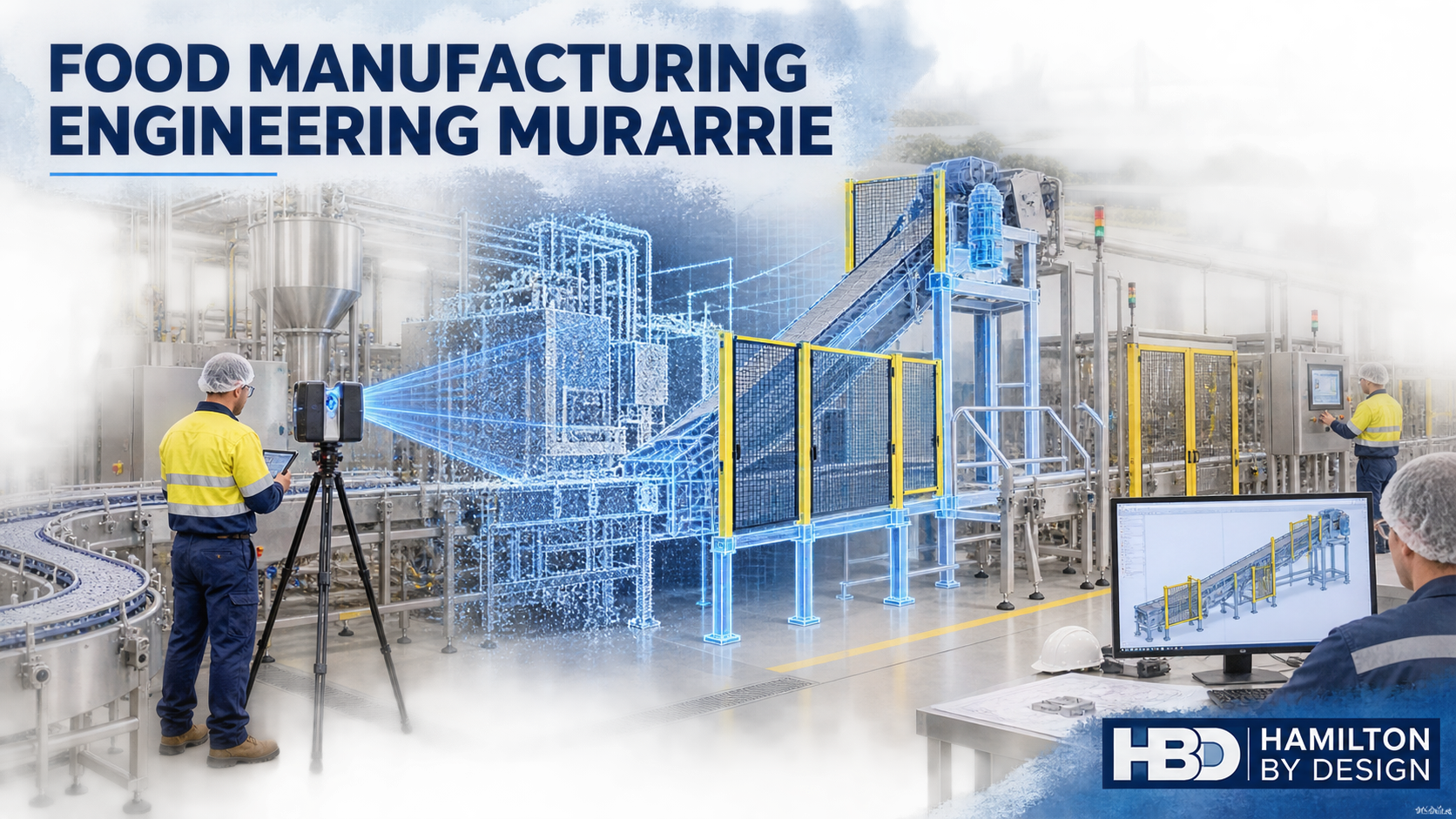
Hamilton By Design 3D scanning a food manufacturing production line in Murarrie, with point-cloud modelling, conveyor design and machine guarding.
Blue 3D LiDAR scanner icon on a tripod with scanning waves

Murarrie is one of Brisbaneโ€™s most strategically located industrial areas. Positioned within the Australia TradeCoast region, the suburb provides direct connections to the Gateway Motorway, Lytton Road, the Port of Brisbane Motorway, Brisbane Airport and the Port of Brisbane. This location makes Murarrie attractive to food manufacturers, packaging businesses, equipment suppliers, warehouses and high-volume distribution operations.

The value of Murarrie, however, extends beyond transport access. Its industrial properties range from established brownfield factories to modern logistics facilities. Food-processing machinery, conveyors, packaging equipment, cool rooms, storage systems and loading areas are often located within the same operational environment. When these facilities are upgraded, accurate information about existing plant conditions becomes essential.

Hamilton By Design provides mechanical engineering, 3D laser scanning, reverse engineering and drafting support for industrial facilities. By combining site capture with practical mechanical design, HBD can help Murarrie businesses plan modifications using reliable spatial information rather than incomplete drawings or assumptions.

Why Murarrie is important to Brisbane manufacturing

Murarrie is approximately 10 kilometres east of Brisbaneโ€™s central business district, but it functions as part of a much larger port, airport and industrial network. From Murarrie, businesses can access metropolitan customers, interstate transport corridors and international freight connections without operating from the CBD.

The local industrial mix includes food ingredients, packaged consumer products, packaging equipment, postal distribution, air-conditioning products, construction materials, paper and industrial fabrication. Modern developments such as Gateway@Murarrie are occupied by organisations including PepsiCo, Australia Post and Daikin, while older sections of the suburb retain manufacturing and process-industry characteristics.

This combination creates a distinctive engineering environment. A project may involve a contemporary distribution centre with automated handling equipment or an older factory in which machinery, pipework and access systems have been modified repeatedly. In both cases, the engineering team needs to understand what is physically present before changing the layout.

The challenge of modifying an operating food factory

Production facilities rarely remain exactly as originally designed. Machines are replaced, conveyors are extended, guarding is altered and services are rerouted. Small changes accumulate until the available drawings no longer match the plant.

In food manufacturing, these discrepancies can affect more than equipment fit. A proposed support, guard or conveyor modification may influence washdown access, drainage, inspection, pest control, maintenance or separation between production activities. The design must account for both the machinery and the way people operate, clean and maintain it.

Traditional tape measurements can be suitable for an isolated component, but they become inefficient in congested production areas. Important relationships between columns, platforms, services, machinery and access routes can easily be missed. Hamilton By Designโ€™s 3D laser scanning services provide a more complete record of these conditions.

A registered point cloud can capture machinery envelopes, conveyor elevations, structural obstructions, floor levels, pipework and surrounding access. The resulting dataset becomes a measurable digital reference for design reviews, relocation studies and future modifications.

From factory scan to practical engineering outcome

The value of laser scanning depends on how the information is used. A point cloud alone does not resolve a production problem; it must be interpreted by people who understand machinery, fabrication and installation.

HBD combines reality capture with 3D scanning engineering in Brisbane. The typical workflow is to scan the relevant area, register and verify the point cloud, model the required assets, develop the proposed modification and produce drawings for review or manufacture.

This integrated process can support:

  • Production-line and packaging-equipment layouts
  • Machine relocation planning
  • Conveyor extensions and transitions
  • Access-platform and guarding modifications
  • Equipment support frames and mounting arrangements
  • Clash detection around existing plant and services
  • Demolition and installation drawings
  • As-built documentation following completion

Because the existing and proposed arrangements can be reviewed in the same 3D environment, project teams can identify spatial conflicts before equipment is disconnected or steelwork is fabricated.

Production-line and packaging-equipment scanning

Packaging lines frequently combine equipment supplied by several manufacturers. Fillers, sealers, labellers, metal detectors, checkweighers, robotic cells, case packers and palletising systems may all have different interface requirements. Their successful integration depends on accurate product-transfer heights, machine clearances and maintenance access.

Scanning can document these relationships without reducing the entire factory to an unnecessarily detailed model. HBD can model the areas and interfaces relevant to the project while retaining the wider point cloud as context. This targeted approach makes the engineering model useful while controlling modelling time and cost.

The retained data can also support future projects. Factory point clouds, packaging-machine models, equipment interfaces, conveyor arrangements and approved CAD assemblies provide a stronger basis for later upgrades than a collection of unrelated field measurements.

Machine relocation and factory-layout planning

Relocating machinery is not simply a matter of placing its footprint on a floor plan. The design team must consider the route into the building, lifting requirements, operator positions, doors and guards, product flow, cleaning access and the space needed to remove components during maintenance.

HBD can develop alternative layouts using scan-based information and SolidWorks 3D modelling services. A relocation study may include:

  • Existing and proposed equipment positions
  • Infeed and discharge interfaces
  • Operator and maintenance envelopes
  • Forklift or crane access
  • Service connection locations
  • Floor penetrations and mounting points
  • Interaction with pedestrian routes
  • Clearances from building elements and surrounding machines

Reviewing these matters digitally can reduce the likelihood of discovering an obstruction during a shutdown, when both time and workable alternatives are limited.

Conveyor, guarding and access modifications

Conveyors are essential to food and packaging operations, but their transfers, drives, rollers and nip points can introduce significant hazards. Modifications should consider production performance and safe access throughout the machinery lifecycle, including cleaning, product clearing, changeovers, fault finding and maintenance.

Hamilton By Design can assist with conveyor arrangements, transition pieces, support frames, guards, covers and access layouts as part of its mechanical engineering consulting services.

Relevant project references may include:

  • AS/NZS 4024 Safety of Machinery series
  • AS 1657 for fixed platforms, walkways, stairs and ladders
  • AS 4991 for lifting devices
  • AS 3990 for mechanical equipment steelwork
  • AS 4041 for pressure piping, where applicable
  • AS 1210 for pressure vessels, where applicable

The applicable standards must be established for each project according to the equipment, hazards, site requirements and contractual scope. Electrical design, specialist hygiene advice, structural certification and professional engineering services requiring Queensland registration should be provided or reviewed by appropriately qualified practitioners.

Reverse engineering obsolete or undocumented components

Production machinery may remain operational long after original suppliers stop supporting it. Replacement parts might have long lead times, incomplete drawings or no reliable identification. In other cases, a locally modified component may never have been documented.

HBDโ€™s reverse engineering and 3D scanning workflow can assist with selected components such as:

  • Guards and covers
  • Brackets and support frames
  • Shafts and hubs
  • Machine interfaces
  • Conveyor components
  • Change-parts
  • Chutes and transition pieces
  • Pump or motor mounting arrangements

Depending on the component and required accuracy, the work may use LiDAR scanning, metrology scanning, conventional measurement or a combination of methods.

The output can include a 3D manufacturing model, detailed drawing, DXF profile or neutral CAD format. Material, tolerances, wear, surface condition and the componentโ€™s function must also be considered. Copying worn geometry without engineering interpretation may simply reproduce an existing problem.

Fabrication and mechanical drafting for plant upgrades

Clear documentation connects the engineering concept with the people who fabricate and install it. HBDโ€™s manufacturing and production services can support the preparation of:

  • General arrangement drawings
  • Equipment and conveyor layouts
  • Fabrication drawings
  • Plate developments and DXF profiles
  • Guards and removable covers
  • Support-frame details
  • Installation and demolition drawings
  • Equipment-interface drawings
  • Final as-built records

Mechanical drawings may be prepared with reference to the AS 1100 technical-drawing series and the standards applicable to the asset being documented.

HBD can provide mechanical and structural drafting. Structural assessment and certification remain the responsibility of the nominated structural engineer.

Machine guarding and workplace safety

Machinery guarding should not be assessed solely according to normal production conditions. Operators and maintenance personnel may be exposed to different hazards during cleaning, clearing blockages, changing products, inspecting equipment or replacing components.

A machinery-safety review may consider:

  • Nip, shear, crush and entanglement hazards
  • Access to conveyor drives and rollers
  • Openings around existing guards
  • Removable and interlocked guards
  • Maintenance and isolation access
  • Emergency-stop visibility and accessibility
  • Falls from platforms or machinery
  • Dropped-object hazards
  • Pedestrian and forklift interaction
  • Restricted maintenance clearances

HBD can document existing arrangements, assist with mechanical risk assessments and prepare drawings for proposed guards or access modifications. A complete risk-management process should involve the plant owner, operators, maintainers and other relevant specialists.

Engineering support for logistics and material handling

Food manufacturing does not end at the production line. Raw ingredients, packaging materials, finished products and waste streams must move safely through the facility.

HBD can assist with logistics-related engineering such as:

  • Factory and warehouse scanning
  • Conveyor and pallet-transfer arrangements
  • Loading-dock layouts
  • Forklift-clearance checks
  • Machinery delivery-path studies
  • Crane and lifting-access layouts
  • Pedestrian-segregation layouts
  • Warehouse equipment clash detection
  • Shutdown delivery sequencing

Potentially relevant standards may include AS 4084 for steel storage racking, the AS 1418 and AS 2550 series for cranes, hoists and winches, AS 4991 for lifting devices and AS/NZS 4024 for machinery and conveyor safety.

Specialist traffic engineering may be required for public-road changes, formal traffic studies or particular development approvals.

Managing Murarrieโ€™s local constraints

Murarrieโ€™s location provides excellent regional access, but individual sites can still present difficult delivery routes, congested loading areas and restricted internal turning space. Equipment-relocation planning should therefore consider the complete path from the property entrance to the final installed position.

Relevant questions include:

  • Can the delivery vehicle enter and turn within the site?
  • Can the equipment pass through the nominated doorway?
  • Is there enough overhead clearance beneath awnings and services?
  • Where can a crane, forklift or mobile lifting device operate?
  • Will unloading interfere with production or emergency access?
  • Can removed machinery leave through the same route?
  • Are temporary works or staged dismantling required?

Parts of the wider Murarrie, Hemmant and Lytton industrial area may also be affected by river, creek, overland-flow or storm-tide flooding. Exposure varies from property to property. Critical equipment, controls, stored materials and business records may require site-specific flood consideration rather than a suburb-wide assumption.

HBD can document plant geometry and equipment elevations, but flood assessment, structural design and statutory certification should be undertaken by the relevant qualified and registered professionals.

Reducing shutdown and installation risk

For an operating manufacturer, lost production can exceed the cost of the design work. The purpose of scan-based engineering is therefore not simply to produce a visually impressive model. It is to improve decisions before the shutdown begins.

An effective workflow can help project teams:

  1. Confirm that new equipment will fit.
  2. Identify clashes with existing plant and services.
  3. Establish installation and removal routes.
  4. Prepare fabrication drawings before the shutdown.
  5. Coordinate contractors around a common model.
  6. Reduce unplanned cutting and rework on site.
  7. Document the final as-built arrangement.

Revision-controlled drawings and models also establish which arrangement was approved and what was ultimately installed.

HBD can retain project information such as point clouds, layouts, equipment models, guarding records, CAD assemblies and modification drawings in accordance with agreed project and confidentiality requirements. This creates a reusable engineering baseline for later maintenance, replacement and expansion work.

Frequently asked questions

What is food manufacturing engineering?

Food manufacturing engineering applies mechanical, production and safety principles to the machinery and systems used to process, move, package and store food products. It can include conveyors, packaging equipment, access systems, machine guarding, equipment supports and factory layouts. Specialist food-safety and hygienic-design advice may also be required, depending on the project.

Can a factory be scanned while production continues?

Often, yes. The scanning plan can be arranged around access restrictions, hygiene controls and production activities. Some concealed areas or machine interfaces may still require controlled access or a shutdown. The proposed scan coverage should be agreed with site personnel before mobilisation.

Does every part of the factory need to be converted into CAD?

No. The point cloud can retain the broader site context while only the machinery, structure and interfaces relevant to the project are modelled. Selective modelling usually provides a more efficient outcome than recreating every visible object.

Can HBD assist with moving a production or packaging line?

Yes. HBD can scan the existing and proposed areas, model machinery envelopes, prepare alternative layouts and document equipment interfaces. Specialist rigging, electrical, structural, food-safety and building-services input may also be required.

Can HBD assess machine guarding?

HBD can document existing guards, identify relevant mechanical hazards and develop guard or access modifications with reference to the AS/NZS 4024 series. A complete risk assessment should involve the plant owner, operators and maintenance personnel because hazards can arise during cleaning, clearing and maintenance as well as normal production.

Can HBD reverse engineer an obsolete machine component?

Potentially, yes. HBD can scan or measure suitable components and produce manufacturing CAD or detailed drawings. Before reproducing a part, its function, material, tolerances, wear and failure history should be reviewed.

What files can be supplied?

Depending on the scope, deliverables may include registered point clouds, PDF drawings, AutoCAD files, SolidWorks models, STEP, Parasolid, DXF, E57, LAS or Autodesk ReCap-compatible data. Required formats should be confirmed at the beginning of the project.

Does Hamilton By Design provide structural certification?

HBD provides mechanical engineering and structural drafting support but does not represent itself as the structural certifier. Where structural certification or Queensland professional engineering approval is required, the work should be reviewed and certified by an appropriately qualified RPEQ.

Engineering support for Murarrie manufacturers

Murarrieโ€™s concentration of production, packaging and distribution facilities creates continuing demand for accurate plant information and practical brownfield engineering.

Whether the task involves relocating a packaging machine, modifying a conveyor, documenting an existing line or reverse engineering an obsolete component, the quality of the outcome begins with understanding the real site conditions.

Hamilton By Design combines 3D scanning, mechanical design, CAD modelling and fabrication drafting within one coordinated workflow. This helps clients progress from site capture to a practical engineering outcome while maintaining clearer responsibility for the information produced.

For assistance with food manufacturing engineering in Murarrie or factory scanning elsewhere in Brisbane, contact Hamilton By Design to discuss the equipment, site constraints, intended outcome and required deliverables.


Hamilton By Design logo displayed on a blue tilted rectangle with a grey gradient background

Contact Us – Talk To Us

Name
Would you like us to arrange a phone consultation for you?
Address

Our clients:

Food and Process Plant Scanning Rocklea: 3D Laser Scanning, Mechanical Design and Scan-to-CAD

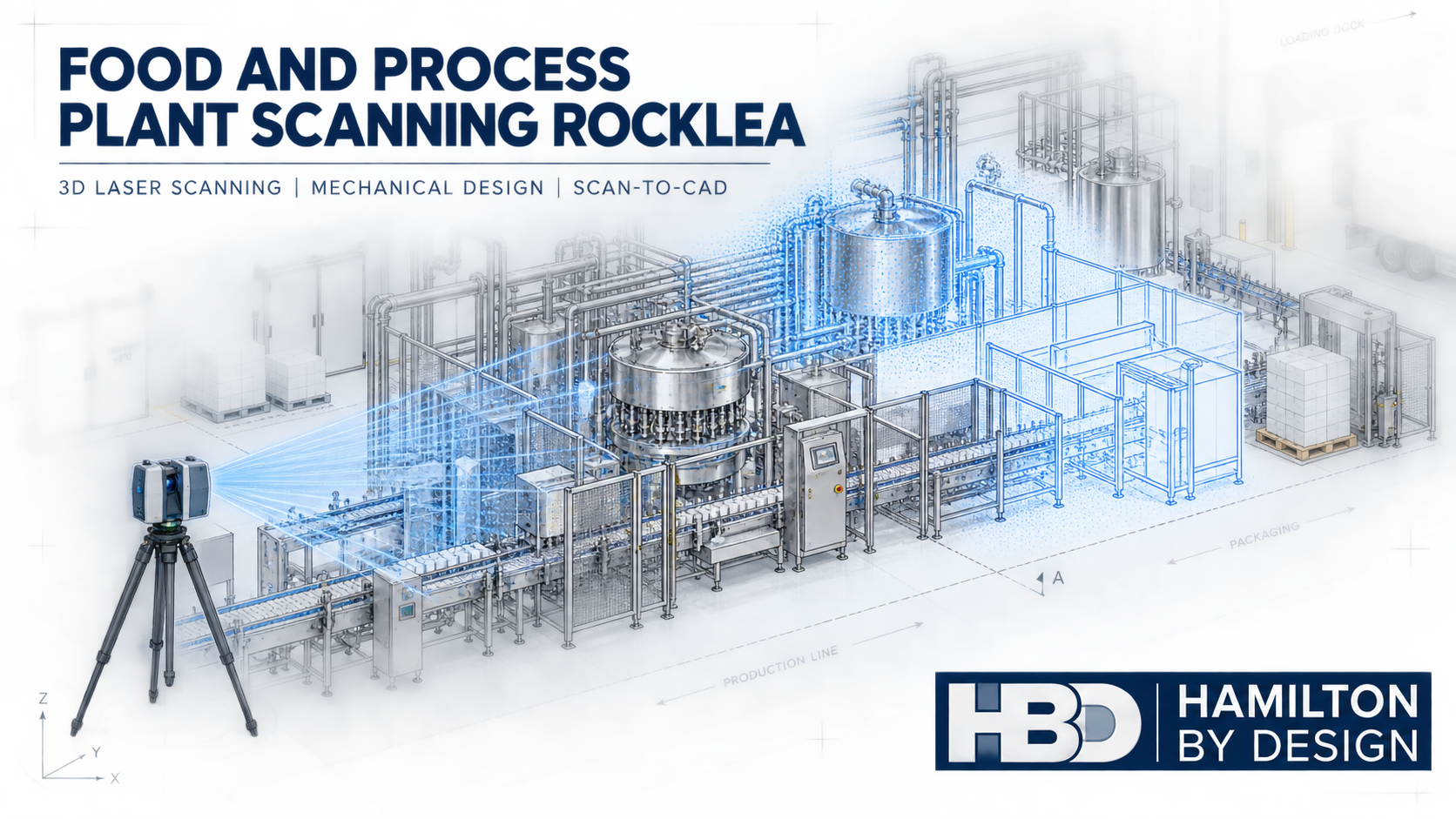
Technical drawing of a Rocklea food and process plant being captured with 3D laser scanning for mechanical design and scan-to-CAD.
Blue 3D LiDAR scanner icon on a tripod with scanning waves

Rocklea is one of Brisbaneโ€™s most established industrial locations. Its combination of food distribution, cold storage, process manufacturing, packaging, machinery services and transport operations gives the suburb an industrial identity that is distinctly different from a modern greenfield estate.

The Brisbane Markets precinct is central to this identity. Fresh produce arrives, moves through wholesale and storage facilities, and is dispatched to businesses across Queensland. Around this activity is a wider network of refrigerated transport providers, food businesses, packaging operations, warehouses, maintenance contractors and industrial service companies.

These businesses frequently operate within facilities that have changed over many years. Production lines are extended, machinery is replaced, conveyors are rerouted and services are added as operational requirements develop. Unfortunately, the original drawings do not always keep pace with these changes.

Hamilton By Design assists Rocklea businesses by combining 3D laser scanning with mechanical engineering, reverse engineering, CAD modelling and fabrication drafting. This engineering-led approach provides accurate information about existing plant and helps turn that information into practical upgrade solutions.

Why Rocklea is different

Rocklea is located approximately 10 kilometres south-west of the Brisbane CBD and has convenient access to the Ipswich Motorway, Beaudesert Road and Ipswich Road. Its proximity to the Acacia Ridge freight precinct also supports the movement of materials and finished goods through road and rail networks.

The suburbโ€™s industrial activity is strongly influenced by food, produce and logistics. This creates operating patterns that are not always obvious to people unfamiliar with Rocklea.

Many businesses begin receiving and dispatching goods well before standard office hours. Trucks, forklifts, produce buyers and warehouse personnel may already be active early in the morning. Food-processing and packaging facilities may also work across multiple shifts, followed by planned cleaning and washdown periods.

This means that plant scanning and engineering inspections must be carefully scheduled. A successful site visit may need to avoid peak receival periods, forklift congestion, sanitation activities or production processes that restrict access.

Rockleaโ€™s flood exposure is another important local consideration. Conditions vary between properties, but flooding has affected parts of the suburb and remains relevant to plant owners, maintenance teams and asset managers. Maintaining accurate digital records of machinery, equipment layouts and services can support future maintenance, recovery planning and asset replacement.

The problem with outdated plant drawings

Older factories often contain a mixture of original equipment, later additions and practical modifications completed during shutdowns. Even when building drawings are available, they may not show the current arrangement of machinery, conveyors, pipework, platforms, guards and services.

Common differences between drawings and actual site conditions can include:

  • Relocated production machinery
  • Modified conveyor elevations
  • Added guards and access gates
  • New pipework and cable routes
  • Changed floor penetrations
  • Altered cold-room arrangements
  • Added platforms or walkways
  • Temporary supports that became permanent
  • Redundant equipment that remains in position
  • Restricted maintenance access
  • Services passing through a proposed installation area

Designing from incomplete information can lead to clashes, fabrication errors and unexpected site work. A relatively small dimensional error can become expensive when a conveyor support does not align, a machine cannot pass through an access opening or a pipe route conflicts with existing equipment.

Hamilton By Designโ€™s LiDAR scanning services across Greater Brisbane help establish a reliable record of visible site conditions. Instead of relying on a limited collection of hand measurements, 3D scanning records millions of measured points that represent the surrounding plant.

What does 3D plant scanning capture?

The scanning scope should be based on the intended engineering outcome. Scanning an entire factory may be appropriate for a major rearrangement, while a localised equipment replacement may only require the machine and its surrounding interfaces.

A Rocklea food or process plant scan may capture:

  • Production and packaging machinery
  • Conveyor routes and transfer points
  • Chutes, hoppers and feed systems
  • Pumps, valves and visible pipework
  • Machinery bases and supports
  • Floors, walls and overhead clearances
  • Cold rooms and insulated panels
  • Platforms, stairs and walkways
  • Machine guards and access gates
  • Drains and visible floor penetrations
  • Loading docks and door openings
  • Ducts, cable trays and overhead services
  • Pallet-staging and maintenance areas

The point cloud can then be supplied directly or converted into selected CAD information. HBDโ€™s Scan-to-CAD services in Brisbane can produce equipment layouts, sections, elevations, general arrangements and three-dimensional models.

Not every object needs to be modelled to the same level of detail. A production-layout study may only require simplified machinery envelopes, whereas a replacement chute or guarding system may require more detailed geometry. Defining the required deliverables before modelling begins helps control cost and ensures that the resulting information is suitable for its intended use.

Scanning around live production

Food and process plants require careful site planning because access, hygiene and production continuity are closely connected.

Before scanning begins, the project team may need to consider:

  • Production schedules
  • Cleaning and washdown periods
  • Site inductions
  • Food-zone access controls
  • Personal protective equipment
  • Moving machinery
  • Forklift and truck movements
  • Restricted areas
  • Temporary pallets or stored products
  • Condensation, steam and reflective surfaces
  • Shutdown or weekend access

Temporary objects should also be identified during the site visit. Pallets, bins, hoses, mobile equipment and stored materials may appear in the point cloud, but they should not automatically be treated as permanent plant.

Where shutdown access is available, scanning can capture areas that are normally obscured or unsafe to approach. Where shutdown access is not practical, the work can often be divided into operational zones and completed progressively.

Conveyor and production-line modifications

Conveyors are essential to many Rocklea food, produce, packaging and distribution operations. They connect processes, reduce manual handling and help maintain consistent product flow. However, altering a conveyor involves more than selecting a new route.

A conveyor modification may need to consider:

  • Product size and weight
  • Required production rate
  • Belt speed and width
  • Transfer heights
  • Product accumulation
  • Drive and take-up locations
  • Cleaning access
  • Guarding
  • Operator work areas
  • Maintenance clearances
  • Forklift movements
  • Upstream and downstream machinery

Hamilton By Design can use captured site conditions to develop conveyor layouts, transfer arrangements, chutes, supports, guards and access provisions. Proposed equipment can be placed within the existing-condition model to identify clashes before fabrication begins.

HBDโ€™s manufacturing and production engineering services connect the scanning process with practical mechanical design and documentation.

This workflow is especially useful in a brownfield plant where there may be limited space between machinery, walls, overhead services and active logistics routes.

Reverse engineering for machinery and spare parts

Some Rocklea plants operate machinery that remains productive despite being many years old. Original suppliers may no longer support the equipment, and drawings for replacement parts may be unavailable.

Replacing an entire machine may not be commercially justified when only a guard, bracket, chute, cover or worn component requires attention.

Hamilton By Designโ€™s reverse-engineering and 3D-scanning services can assist with:

  • Guards and covers
  • Brackets and mounting plates
  • Conveyor components
  • Chutes and transitions
  • Equipment bases
  • Frames and housings
  • Machinery interfaces
  • Obsolete replacement parts
  • Components intended for local manufacture

Reverse engineering is not simply a process of copying a worn object. The condition of the component must be considered because corrosion, wear, distortion and previous repairs may have changed its geometry.

Material, tolerances, fit, loading and manufacturing methods should also be reviewed before a replacement component is released for production.

Machine guarding and safer access

Food and packaging machinery may expose workers to rollers, belts, chains, shafts, blades, couplings and other moving components. Conveyor drives, pulleys, transfers and take-up arrangements can also create trapping or entanglement hazards.

Hamilton By Design can capture existing guarding and machinery clearances, assist with mechanical guarding concepts and prepare drawings for fabrication.

Potential work may include:

  • Fixed machine guards
  • Belt and coupling covers
  • Conveyor nip-point guards
  • Perimeter barriers
  • Access gates
  • Removable maintenance panels
  • Guard-support frames
  • Improved stairs and platforms
  • Maintenance-access layouts

The AS/NZS 4024 series may apply to machinery safety, while AS 1657 may be relevant to fixed platforms, walkways, stairs and ladders. The applicable requirements should be confirmed for the individual machine, task and workplace.

Guarding should be considered as part of a broader plant risk-management process. The review should examine how operators use the machine, how cleaning is performed, how jams are cleared and how maintenance personnel gain access.

Designing for cleaning and maintenance

Food-production equipment must be accessible for cleaning as well as operation. A layout that improves throughput may create new problems if it leaves narrow gaps, traps product or prevents workers from reaching areas that require inspection.

The relationship between equipment and the surrounding area can influence:

  • Washdown access
  • Drainage
  • Standing water
  • Product accumulation
  • Pest harbourage
  • Corrosion
  • Access beneath conveyors
  • Removal of guards
  • Maintenance of motors and bearings
  • Separation of different work zones

A registered point cloud helps the project team understand these relationships before equipment is moved or fabricated.

Hamilton By Design can provide the scanning, mechanical design and drafting information, while the clientโ€™s production and food-safety personnel can review the proposed arrangement against site-specific hygiene procedures.

Internal logistics and material movement

Rockleaโ€™s food and process operations depend on the efficient movement of materials. Incoming goods may pass through receiving, cold storage, preparation, processing, packing, palletising and dispatch.

A production-line modification can affect this entire sequence. New machinery may improve one process while unintentionally reducing forklift access or occupying an important pallet-staging area.

HBD can capture and document:

  • Loading docks
  • Door openings
  • Cold-room access
  • Pallet-staging areas
  • Conveyor connections
  • Forklift and pedestrian interfaces
  • Machinery-removal routes
  • Maintenance areas
  • Storage and dispatch interfaces

Alternative arrangements can then be developed using reliable spatial information. This supports discussions between operations, maintenance, safety and project personnel before a preferred layout is selected.

Mechanical drafting and fabrication drawings

Once a design has been reviewed, Hamilton By Design can develop mechanical documentation for quoting, fabrication and installation.

Typical deliverables include:

  • General arrangement drawings
  • Production-line layouts
  • Conveyor drawings
  • Chute and transition drawings
  • Machine-guarding details
  • Platform and access layouts
  • Pipe-routing drawings
  • Workshop and fabrication drawings
  • Cutting profiles and DXF files
  • STEP and Parasolid models
  • Installation drawings
  • As-built updates

HBDโ€™s engineer-led SolidWorks drafting services in Queensland help maintain continuity between site capture, mechanical modelling and fabrication documentation.

This continuity is important because the person preparing the drawings can work directly with the captured site data rather than relying on information passed through several unrelated providers.

A practical scan-to-upgrade process

A Rocklea plant-upgrade project can generally follow five stages.

First, the client and HBD define the operational problem, required deliverables and limits of the work.

Second, HBD scans the relevant plant, machinery and surrounding interfaces.

Third, the point cloud is registered and checked before the required CAD information is produced.

Fourth, proposed modifications are developed and reviewed with the clientโ€™s operations, maintenance and safety personnel.

Finally, approved drawings and models are issued for fabrication or installation under an agreed revision process.

Where appropriate, an additional scan can document the completed installation and update the plantโ€™s digital records.

Frequently asked questions

Can Hamilton By Design scan an operating food factory?

Yes. Scanning can often be scheduled around production, cleaning and dispatch activities. Access requirements, hygiene controls and moving equipment should be discussed before the visit.

What is a point cloud?

A point cloud is a digital collection of millions of measured points representing visible surfaces within the scanned area. It allows the site to be viewed and measured after the scanning work is complete.

Can a point cloud be converted into CAD drawings?

Yes. Selected parts of the point cloud can be converted into equipment layouts, general arrangements, sections, elevations and three-dimensional CAD models.

Can HBD scan a single machine or conveyor?

Yes. The scope can range from one component or machine interface to a complete production area. The surrounding geometry should be sufficient to support the intended modification.

Can laser scanning detect hidden services?

No. Laser scanners record visible surfaces and cannot see through walls, floors, cladding or equipment. Concealed services may require existing records or specialist detection methods.

Can HBD assist with machinery relocation?

Yes. HBD can scan the existing machinery and its proposed destination, develop layout information and assist with mechanical interface and clearance checks.

Can HBD help with machine guarding?

Yes. HBD can document existing conditions, assist with mechanical guarding concepts and prepare fabrication drawings. The work should form part of the clientโ€™s wider machinery risk-management process.

What project data can HBD retain?

Subject to agreed confidentiality and retention requirements, HBD can retain point clouds, equipment layouts, CAD models, machinery interfaces, guarding surveys and modification drawings.

Engineering support for Rocklea plants

Rockleaโ€™s concentration of food handling, manufacturing, packaging, cold storage and distribution creates substantial opportunities for plant improvement. It also creates engineering challenges because modifications must often be completed within congested facilities and limited shutdown periods.

Accurate existing-condition data provides a stronger foundation for these decisions.

Hamilton By Design combines industrial 3D scanning with mechanical engineering, reverse engineering, CAD modelling and fabrication drafting. From a single machinery interface to a complete production-line upgrade, the objective is to reduce assumptions and provide practical information that clients, fabricators and installers can use.

For assistance with food-production-line scanning, factory scan-to-CAD, conveyor modifications, machine guarding or reverse engineering in Rocklea, contact Hamilton By Design to discuss the plant, the proposed change and the required deliverables.


Hamilton By Design logo displayed on a blue tilted rectangle with a grey gradient background

Contact Us – Talk To Us

Name
Would you like us to arrange a phone consultation for you?
Address

Our clients:


3D Laser Scanning Warriewood & Mona Vale | HBD

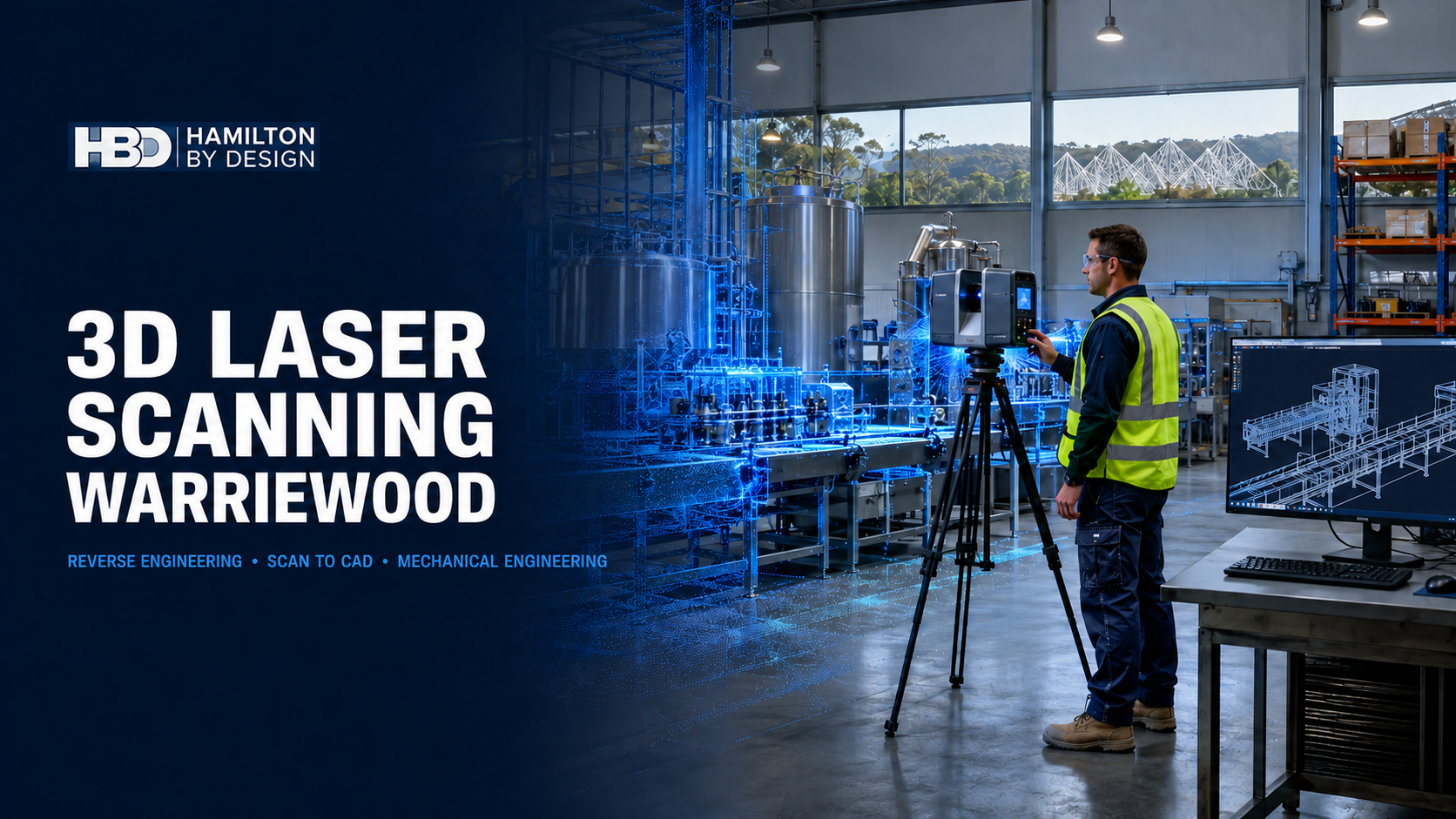
Mechanical engineer performing 3D laser scanning inside a Warriewood factory, with point-cloud data and a scan-to-CAD model.

3D Laser Scanning Warriewood and Engineering Support for Mona Vale Industry

Blue 3D LiDAR scanner icon on a tripod with scanning waves

The Warriewood and Mona Vale industrial area is an important employment precinct on Sydneyโ€™s Northern Beaches. Although the region is better known for its beaches, residential neighbourhoods and natural environment, it also supports light manufacturing, food-processing technology, electronic products, industrial equipment suppliers, workshops, warehousing and specialised technical businesses.

These operations depend on factories, machinery and physical components that must be maintained, modified and periodically replaced. However, the engineering information needed to undertake that work is not always complete. Original drawings may be unavailable, machinery may have been modified without documentation, and imported replacement parts can be difficult to obtain.

Hamilton By Design provides 3D scanning services in Sydney to help businesses capture existing facilities, machinery and equipment. The resulting point clouds and CAD models can support reverse engineering, factory modifications, equipment relocation, fabrication and long-term asset documentation.

A distinctive Northern Beaches industrial precinct

Warriewood and Mona Vale differ from the large industrial estates of Western Sydney. The precinct contains a mixture of factories, technical businesses, warehouses, workshops, offices and residential development within a relatively constrained coastal area.

Northern Beaches Council describes the regional economy as a combination of established industrial zones, manufacturing businesses, small and medium enterprises, โ€œmicro innovatorsโ€ and global companies. Warriewood contributes to this economy through a concentration of businesses around Jubilee Avenue, Daydream Street, Apollo Street, Ponderosa Parade and the surrounding industrial streets.

The precinct includes health-products production and distribution, food-processing machinery, electronics manufacturing, audiovisual technology, fabrication equipment, machinery servicing and warehouse operations. Businesses range from major facilities to smaller specialist workshops occupying strata industrial units.

At the same time, Warriewood Valley has undergone substantial residential and commercial growth. Northern Beaches Council states that the wider land-release area now covers approximately 195 hectares and anticipates 2,544 dwellings together with community infrastructure and employment-generating development.

This changing land-use pattern creates engineering challenges. Industrial operators must use their available floorspace efficiently while managing access, noise, drainage, delivery movements, equipment safety and their interfaces with surrounding properties.

From โ€œGlass Cityโ€ to a modern technology and industrial area

One of the most interesting aspects of Warriewood is its agricultural history.

During the middle of the twentieth century, Warriewood Valley was known as โ€œGlass Cityโ€ because approximately 3,500 glasshouses covered the area at the peak of production between 1947 and 1954. Many were used to grow tomatoes by migrant families from Italy and the former Yugoslavia.

This history remains visible in the names of local streets. Jubilee, Daydream, Apollo, Ponderosa and Prosperity were tomato varieties grown in Warriewood. Today, these names are associated with business premises, warehouses and industrial operations, but they preserve a direct connection to the valleyโ€™s earlier production economy.

Warriewood also contains an important environmental feature. The 26-hectare Warriewood Wetlands is described by Northern Beaches Council as the largest remaining low-lying freshwater sandplain ecosystem in northern Sydney. The wetlands contribute to flood mitigation, nutrient recycling and sediment filtration.

The relationship between industrial land, residential development, creeks and wetlands makes Warriewood unusual. Factory and warehouse projects may need to consider flooding, stormwater, equipment elevations, external access and environmental interfaces alongside normal production requirements.

Industrial operations in Warriewood and Mona Vale

The local business base demonstrates the range of engineering requirements that can arise within the precinct.

The Blackmores campus in Warriewood combines offices, production and distribution. Published information about the site describes a 25,000-square-metre facility, storage for approximately 5,000 pallets, a production and distribution operation running 24 hours a day for six days each week, and thousands of weekly shipments.

CBS Foodtech supplies and supports machinery used in food manufacturing. Its applications centre includes processes such as mincing, mixing, filling, cutting, slicing, cooking, smoking and packaging. These operations involve complex machinery, cleaning requirements, product flow, conveyors, access and guarding.

Pivot Electronics designs and manufactures electrical products for rail, utilities, industrial automation, mining, solar and telecommunications applications. Product-based businesses of this kind may require mechanical enclosures, brackets, mounting systems, prototype parts and controlled CAD records.

Amber Technology operates warehouse, service and technical-support activities for professional audiovisual, communications, security and entertainment equipment. Power Machinery Australia, based in Mona Vale, supplies and services equipment such as bandsaws, press brakes, guillotines, fibre lasers, folding machines and workshop machinery.

These companies are examples of the precinctโ€™s industrial character and are not represented as existing Hamilton By Design clients. They illustrate the types of local operations that may benefit from engineering services across Sydney.

Why existing-condition information matters

An engineering project is only as reliable as its starting information.

Factories commonly change over time. Machines are moved, platforms are added, pipework is rerouted and storage areas are reorganised. When these modifications are not incorporated into the facility drawings, later projects may be designed from information that no longer represents the actual installation.

Manual measurement can provide individual dimensions, but it may not adequately record the relationships between machinery, structures, services and access routes. Missed dimensions can cause fabrication errors, installation delays or the need for site modifications.

Hamilton By Design provides industrial 3D scanning in Sydney to capture the observable condition of a facility. A registered point cloud can record:

  • machinery positions;
  • floor and equipment levels;
  • building columns;
  • access platforms;
  • conveyors;
  • storage areas;
  • door openings;
  • services and pipe routes;
  • equipment clearances; and
  • surrounding structures.

The point cloud becomes a reference dataset from which plans, elevations, sections and three-dimensional models can be developed.

Factory scanning Warriewood

Factory scanning is particularly useful in Warriewood because many businesses operate within relatively constrained premises. New equipment may need to fit around existing machinery, racking, fire services, columns and production areas.

A scan can support the investigation of machinery footprints, maintenance access, operator space and installation routes before equipment is purchased or fabricated. It can also help determine whether an assembled machine can pass through an existing opening or whether it must be delivered in separate modules.

Hamilton By Designโ€™s 3D laser scanning for industrial plants connects reality capture with practical engineering requirements. The objective is not merely to create a visual point cloud. It is to produce information that can assist designers, fabricators, installers and asset owners.

For larger areas, Hamilton By Design can use a FARO Focus S70 terrestrial laser scanner. Smaller components and detailed product geometry may be captured using a component scanner. The appropriate method depends on the size of the subject, required accuracy, surface condition and intended deliverable.

Scan to CAD Warriewood

A point cloud contains large quantities of spatial information, but it is not automatically a fabrication or manufacturing model. Engineering interpretation is required to convert the captured surfaces into suitable CAD geometry.

Through point-cloud-to-CAD services, Hamilton By Design can create:

  • simplified equipment models;
  • factory layouts;
  • machinery envelopes;
  • existing-condition drawings;
  • mechanical assemblies;
  • fabricated components;
  • equipment interfaces; and
  • installation models.

The required level of detail should be established at the start of the project. A model intended for spatial coordination does not necessarily require every fastener and small feature. A model intended for component manufacture requires greater attention to datums, functional surfaces, tolerances, fits and material requirements.

Hamilton By Designโ€™s broader scan-to-CAD services in Sydney can provide outputs including STEP, Parasolid, DXF, PDF, E57 and Autodesk ReCap-compatible files, depending on the agreed scope.

Reverse engineering Mona Vale

Industrial and workshop machinery can remain in operation for decades. During that time, original suppliers may cease trading, parts may be discontinued and machinery may be modified to suit changing production requirements.

Reverse engineering and 3D scanning can help recover the geometry of an existing component. Potential examples include:

  • machine guards and covers;
  • brackets and mounting plates;
  • shafts and couplings;
  • housings;
  • change parts;
  • guides and product-contact components;
  • fabricated transitions;
  • equipment supports; and
  • replacement mechanical assemblies.

The physical component is scanned and interpreted to create suitable CAD geometry. Critical interfaces may also require manual measurement or other inspection methods, especially for threads, bores, bearing seats and inaccessible features.

A scan cannot independently identify material grade, heat treatment, design load or the original manufacturing tolerance. These matters should be established through available records, testing, operating information and engineering assessment.

The completed CAD model can provide a controlled technical baseline for local manufacture, modification or future replacement.

Mechanical engineering Northern Beaches

Hamilton By Design offers mechanical engineering services in Sydney that connect existing-condition capture with practical design development.

Services relevant to Warriewood and Mona Vale may include:

  • machinery and equipment design;
  • reverse engineering;
  • conveyor and materials-handling modifications;
  • equipment bases and support frames;
  • maintenance-access improvements;
  • machine guarding;
  • lifting-device design and verification;
  • production-layout studies;
  • static and fatigue FEA;
  • wear and existing-condition studies; and
  • fabrication support.

Potentially applicable standards include the AS/NZS 4024 Safety of Machinery series, AS ISO 12100 for machinery risk assessment and risk reduction, AS 3990 for mechanical equipment steelwork, AS 4100 for steel structures and AS/NZS 1554 for welded fabrication.

Platforms, walkways, stairs and ladders may require consideration of AS 1657. Lifting devices may fall within AS 4991, while cranes, hoists and their use may involve the AS 1418 and AS 2550 series.

The applicable standard depends on the machine, duty, material, hazards, site requirements and contractual scope. A standard should only be nominated after its relevance to the particular project has been established.

Mechanical drafting and fabrication documentation

A three-dimensional model communicates shape, but manufacturers also require clearly defined production information.

Hamilton By Design provides mechanical drafting services in Sydney for:

  • general arrangement drawings;
  • component and machining drawings;
  • fabrication drawings;
  • welded assemblies;
  • sheet-metal details;
  • flat patterns;
  • bills of materials;
  • exploded assemblies;
  • equipment layouts;
  • installation drawings; and
  • as-built records.

Technical drawings may be prepared with reference to AS 1100.101 for general drawing principles and AS 1100.201 for mechanical engineering drawing. Steelwork drawings may also need to reflect AS 3990, AS 4100, AS/NZS 1554 and the clientโ€™s fabrication requirements.

Dimensions, tolerances, materials, finishes, welds, datums and inspection requirements should be defined according to the intended manufacturing process. A scan-derived model should not be issued for manufacture without suitable review and engineering interpretation.

Hamilton By Design also offers 3D scanning for fabrication in Sydney, helping fabricators design against actual installation interfaces rather than incomplete or assumed dimensions.

Machinery safety and guarding

The Warriewoodโ€“Mona Vale precinct contains food-processing machinery, metalworking equipment, production machinery, conveyors and workshop plant. These assets can introduce cutting, crushing, drawing-in, entanglement, impact and ejection hazards.

Hamilton By Design can provide machine-guarding assistance including machinery surveys, fixed and removable guarding concepts, access layouts and fabrication drawings.

Three-dimensional scanning can record the actual positions of drives, frames, control panels, access platforms and surrounding obstructions. This allows guarding to be developed around the real installation.

A suitable risk review should consider:

  • normal operation;
  • cleaning;
  • adjustment;
  • fault finding;
  • maintenance;
  • foreseeable misuse;
  • isolation requirements;
  • guard removal; and
  • safe access.

The AS/NZS 4024 series and AS ISO 12100 provide important guidance for machinery risk reduction. SafeWork NSWโ€™s plant code also requires hazards to be identified and risks eliminated or minimised so far as reasonably practicable.

Specialist electrical, functional-safety, hazardous-area, food-hygiene or fire-engineering input may be required in addition to the mechanical scope.

Production and logistics improvements

Warriewood includes significant warehouse and distribution activity. Common issues include congested storage, inefficient picking routes, limited loading space and interaction between vehicles and pedestrians.

Hamilton By Designโ€™s manufacturing layout design services can use scanned existing conditions to investigate:

  • machinery placement;
  • pallet and storage areas;
  • conveyor routes;
  • pedestrian access;
  • forklift movements;
  • maintenance clearances;
  • loading and unloading areas;
  • emergency access; and
  • future production expansion.

Steel storage racking may require consideration of AS 4084.1:2023 and AS 4084.2:2023. Conveyors and powered machinery may involve the AS/NZS 4024 series. Lifting frames, spreaders and other lifting devices may require AS 4991, while cranes and hoists can involve the AS 1418 and AS 2550 series.

A digital layout allows alternatives to be compared before machinery, racks or services are physically moved.

Environmental and site risks

Warriewoodโ€™s low-lying landscape, creek system and proximity to the coast create additional considerations for industrial projects.

Potential issues include:

  • surface-water entry;
  • localised flooding;
  • restricted stormwater routes;
  • corrosion of external equipment;
  • slippery access surfaces;
  • environmental constraints;
  • equipment installed at unsuitable levels; and
  • reduced emergency or maintenance access during severe weather.

LiDAR scanning can record visible levels, drainage features, equipment positions and access routes. This information may assist further engineering, drainage or environmental assessments.

Hamilton By Design is a mechanical engineering consultancy. Specialist civil, hydraulic, structural, environmental or flood-engineering advice should be obtained where those disciplines govern the project.

Engineering data as a long-term asset

One of the enduring benefits of 3D scanning is the creation of a digital existing-condition record.

Hamilton By Design can retain agreed project information such as facility scans, equipment CAD, component geometry, drawings and dimensional records. A controlled dataset can reduce repeated site visits and provide a starting point for later modifications.

Good engineering data governance should distinguish between raw scans, working models, approved designs, fabrication revisions and final as-built information.

For smaller businesses, this approach creates greater continuity when staff, contractors or equipment suppliers change.

Frequently asked questions

What can Hamilton By Design scan in Warriewood?

Hamilton By Design can scan factories, warehouses, machinery, equipment interfaces, access systems and individual components. The selected scanning method depends on the asset size, required accuracy and intended output.

Can scanning be completed while a factory is operating?

Often it can. The scanning plan must consider moving machinery, people, restricted areas, hygiene requirements and site safety. Some areas may need controlled access or a shutdown period.

Is a point cloud the same as a CAD model?

No. A point cloud is captured spatial data. A CAD model is interpreted engineering geometry developed from that data. The modelling effort depends on the required detail and purpose.

Can Hamilton By Design reverse engineer an obsolete component?

Yes, subject to access, condition and the required accuracy. The physical geometry can be captured and reconstructed, but material properties, internal features and original design loads may require additional investigation.

Can the scan be used to check whether new machinery will fit?

Yes. Supplier models can be positioned within the scanned environment to investigate footprints, clearances, access and potential clashes before installation.

What file formats can be supplied?

Possible formats include E57, RCP, STEP, Parasolid, DXF, PDF and native SolidWorks files where included in the agreed deliverables.

Can Hamilton By Design provide fabrication drawings?

Yes. Drawings can be developed for components, guards, equipment supports, assemblies and installation arrangements. The content depends on the manufacturing process and project scope.

Can Hamilton By Design help with machine guarding?

Yes. Hamilton By Design can survey existing machinery, develop mechanical guarding concepts and prepare fabrication drawings with reference to applicable machinery-safety requirements.

Can warehouse and production layouts be developed from scans?

Yes. Point clouds can support layouts for equipment, racks, conveyors, access routes and production cells. They can also assist with relocation and future-expansion planning.

Does Hamilton By Design retain the project information?

Hamilton By Design can retain agreed facility scans, CAD models, component data, drawings and existing-condition records subject to the projectโ€™s confidentiality and data-management requirements.

Additional Sydney-wide resources include:

3D laser scanning Warriewood and Mona Vale

Warriewood and Mona Vale support a technically diverse group of manufacturers, equipment suppliers, food businesses, workshops, warehouses and technology companies. Their physical assets must operate within a constrained and changing coastal precinct.

Hamilton By Design can help these businesses document existing facilities, recover component geometry, plan equipment modifications and create practical manufacturing information.

By integrating 3D laser scanning Warriewood, reverse engineering Mona Vale, mechanical engineering Northern Beaches, factory scanning Warriewood and scan-to-CAD Warriewood, Hamilton By Design provides a coordinated pathway from the physical asset to controlled engineering data, CAD models and fabrication drawings.


Hamilton By Design logo displayed on a blue tilted rectangle with a grey gradient background

Contact Us – Talk To Us

Name
Would you like us to arrange a phone consultation for you?
Address

Our clients:
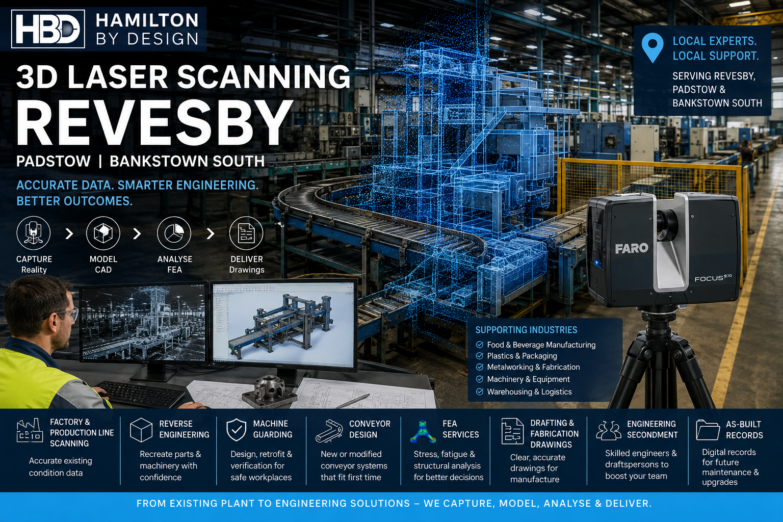


3D Laser Scanning Revesby | Factory Scanning & Mechanical Engineering

Blue 3D LiDAR scanner icon on a tripod with scanning waves

Revesby, Padstow and the southern Bankstown industrial area form a long-established manufacturing corridor supporting food production, plastics, metalworking, packaging, machinery, warehousing and production-line operations. In these facilities, engineering projects often begin with the same challenge: the machinery, conveyors and structures physically exist, but the available drawings do not always represent what is actually installed.

Hamilton By Design provides 3D laser scanning in Revesby to establish accurate existing-condition information before machinery is modified, relocated, reverse engineered or integrated into a wider plant upgrade.

Using 3D Laser Scanning Services, manufacturers can capture production machinery, conveyors, structures and surrounding interfaces as measurable point-cloud data. That information can then support reverse engineering, mechanical design, machine guarding, fabrication drawings, FEA and future as-built documentation.

The objective is not simply to create a 3D scan. It is to reduce uncertainty before engineering decisions are made.

Managing Engineering Risk in Existing Factories

Brownfield manufacturing projects carry a particular type of engineering risk.

Unlike a greenfield project, the designer is rarely working with an empty site. New equipment has to fit around existing machinery, structural steel, pipework, conveyors, guarding, access systems and production constraints.

Historical drawings may still be available, but they may not include decades of plant modifications.

A conveyor may have been moved.

A gearbox may have been replaced.

A machine frame may have been reinforced.

Guards may have been added.

Services may have been rerouted.

This means an apparently simple modification can become expensive if the project begins from incorrect existing-condition information.

Hamilton By Design can help manage this risk by establishing the physical arrangement before detailed design begins.

A practical sequence is:

capture reality โ†’ verify interfaces โ†’ engineer the modification โ†’ analyse where required โ†’ document for fabrication โ†’ retain the as-built record

This gives project teams a stronger information base than relying on drawings that may no longer match the factory.

Production-Line and Factory Scanning in Revesby

Production-line scanning is particularly useful where several pieces of equipment interact.

A typical scan can capture:

  • production machinery;
  • conveyors;
  • transfer points;
  • floors and walls;
  • columns;
  • structural steel;
  • electrical cabinets;
  • guarding;
  • access platforms;
  • pipework;
  • neighbouring equipment.

Hamilton By Design’s 3D Laser Scanning Services can create a registered point cloud representing the actual plant condition.

This point cloud then becomes a measurable engineering reference.

Rather than sending engineers and draftspersons back to site repeatedly for individual dimensions, the project team can work from a broader digital record of the area.

This is especially valuable during factory upgrades where access may be restricted by production schedules.

Why Existing Drawings Are Not Always Enough

One of the largest risks in established manufacturing facilities is assuming that an old drawing is still correct.

Even a good original drawing may not include:

  • modifications made by maintenance teams;
  • locally fabricated replacement parts;
  • revised conveyor supports;
  • additional guards;
  • new drives;
  • altered access arrangements;
  • production-line expansions;
  • relocated equipment.

For this reason, existing drawings should often be considered valuable background information rather than unquestioned dimensional truth.

3D scanning provides an opportunity to compare the documentation with the actual plant.

Where discrepancies exist, they can be identified before new equipment is fabricated.

This can help reduce rework, installation delays and unexpected shutdown work.

Reverse Engineering Padstow and Revesby Machinery

Not all engineering problems involve the entire production line.

Sometimes the problem is a single component.

A machine may contain a bracket, housing, guard, chute, shaft support or fabricated assembly that is no longer available from the original manufacturer.

Where drawings or CAD files are missing, Hamilton By Design can use Reverse Engineer 3D Scanning to capture the existing geometry and reconstruct usable engineering information.

Typical reverse-engineering projects may involve:

  • machine frames;
  • bearing housings;
  • fabricated brackets;
  • conveyor components;
  • equipment guards;
  • chutes;
  • covers;
  • supports;
  • obsolete replacement parts;
  • machine interfaces.

The objective is generally to move from a physical component toward a practical CAD and drawing package that can support repair, redesign or manufacture.

From Scan Data to CAD

Raw point-cloud data is valuable, but many manufacturing projects require a further step.

The captured geometry can be used to develop CAD models representing machinery, conveyors, guards or fabricated structures.

Hamilton By Design’s Mechanical Engineering Services can combine site capture with mechanical design to develop practical modifications around the existing plant.

Depending on the project, the CAD model may include:

  • equipment envelopes;
  • conveyor centre lines;
  • support structures;
  • drive arrangements;
  • machine guards;
  • mounting plates;
  • fabricated assemblies;
  • replacement components.

This allows the proposed modification to be reviewed digitally before fabrication begins.

Conveyor Design and Production-Line Modifications

Conveyors are a common interface between existing and new equipment.

A production change may require:

  • extending a conveyor;
  • modifying its elevation;
  • changing a transfer point;
  • installing a new drive;
  • rerouting product flow;
  • introducing a new support structure;
  • connecting a new machine.

The challenge is that the conveyor must fit the existing factory.

Scanning the surrounding plant allows the new geometry to be designed around actual installed conditions rather than assumed dimensions.

Hamilton By Design’s broader Mechanical Engineering Consulting capability can support plant modifications, conveyor systems and brownfield engineering projects where maintainability, access and installation constraints must be considered together.

Machine Guarding Revesby

Machine guarding should also be considered whenever production machinery is modified.

A new conveyor, drive, motor or machine configuration can affect the existing safeguarding arrangement.

Hamilton By Design provides Machine Guarding Engineering and Verification for industrial machinery and fixed plant.

3D scanning can assist by capturing the relationship between the machinery, guards, structures and operator access.

Potential guarding projects may involve:

  • fixed guards;
  • belt guards;
  • pulley guards;
  • coupling guards;
  • rotating-shaft guards;
  • mesh enclosures;
  • perimeter guarding;
  • access gates;
  • retrofit modifications.

By designing the guarding within the same CAD environment as the machinery, the engineer can consider fit, access and maintenance requirements together.

FEA for Modified Machinery and Supports

Geometry is only one part of engineering risk.

Where a component or structure is being redesigned, it may also be necessary to understand how it behaves under load.

Hamilton By Design can incorporate finite element analysis into suitable mechanical engineering projects.

FEA may assist with evaluating:

  • stress;
  • displacement;
  • stiffness;
  • fatigue behaviour;
  • buckling;
  • load paths;
  • modified plate thicknesses;
  • reinforcement arrangements.

A typical workflow might be:

3D scan โ†’ CAD model โ†’ mechanical design โ†’ FEA โ†’ fabrication drawing

This can be particularly useful for conveyor supports, machine frames, brackets and reverse-engineered components where the project is not simply reproducing an existing part but modifying or improving it.

Hamilton By Design’s FEA Capabilities provide a natural extension of the scanning and mechanical design process.

Mechanical Drafting and Fabrication Drawings

A successful scan is not necessarily the final project deliverable.

Fabricators and installers need clear engineering information.

Hamilton By Design’s Mechanical Drafting Services Sydney can convert site and design information into documentation suitable for manufacturing and installation.

Deliverables may include:

  • general arrangement drawings;
  • fabrication drawings;
  • assembly drawings;
  • detail drawings;
  • bills of materials;
  • DXF cutting profiles;
  • STEP files;
  • DWG files;
  • PDF drawing packages.

For a Revesby manufacturer, this means one engineering workflow can progress from scanning the existing plant through to producing practical workshop documentation.

Engineering Secondment for Manufacturing Projects

Not every client needs an external consultant to manage the complete project.

Many factories already have experienced plant engineers, maintenance teams and project managers. Their problem is often capacity rather than knowledge.

Hamilton By Design’s Engineering Secondment Services can provide additional technical resources during periods of high workload.

Secondment can support:

  • shutdown preparation;
  • plant upgrades;
  • production-line modifications;
  • engineering backlogs;
  • CAD modelling;
  • drafting;
  • site verification;
  • reverse-engineering programs;
  • project engineering activities.

This can allow Hamilton By Design personnel to work alongside the client’s existing engineering team rather than operating as a separate project function.

For busy manufacturing facilities, that flexibility can be particularly useful when several plant changes need to be delivered within a limited shutdown or project window.

Creating a Digital As-Built Record

One of the longer-term advantages of 3D laser scanning is that the project data can remain useful after the immediate modification is complete.

Hamilton By Design can retain engineering data such as:

  • registered production-line point clouds;
  • machinery models;
  • conveyor layouts;
  • guarding models;
  • fabrication drawings;
  • CAD assemblies;
  • STEP files;
  • FEA records;
  • updated as-built drawings.

This means a scan commissioned for one plant upgrade can potentially support later projects.

For example, a production line scanned in 2026 may later require another conveyor modification, new guarding or an additional piece of equipment.

Instead of beginning again with no reliable information, the project can start from an established digital record and then verify only what has changed.

This creates a gradual digital engineering history of the factory.

Supporting Revesby, Padstow and Bankstown Manufacturing

Hamilton By Design can support manufacturing and industrial businesses throughout Revesby, Padstow, Bankstown South and surrounding South-West Sydney industrial areas.

Projects may range from a single reverse-engineered component through to scanning an entire production area prior to a major upgrade.

The combination of 3D Laser Scanning, mechanical engineering, reverse engineering, machine guarding, drafting, FEA and engineering secondment means the service can be adapted to the actual engineering problem rather than treating scanning as an isolated deliverable.

The underlying objective is straightforward:

establish what really exists before deciding what needs to change.

Frequently Asked Questions

What can be captured during a factory scan?

A factory scan can include machinery, conveyors, structural steel, platforms, floors, walls, pipework, guards and other surrounding equipment required for the engineering project.

Can machinery be scanned while it remains installed?

In many cases, yes. Terrestrial laser scanning is well suited to capturing fixed machinery and production-line environments in situ.

Can 3D scanning help with conveyor modifications?

Yes. Existing conveyors and surrounding equipment can be captured so new conveyor geometry, supports and transfer arrangements can be designed against actual plant conditions.

Can Hamilton By Design reverse engineer a machine component?

Yes. Where suitable access and information are available, components can be scanned or measured and reconstructed into CAD models and manufacturing documentation.

Can machine guards be designed from scan data?

Yes. Existing machinery can be captured and guard geometry developed around actual equipment, access and structural interfaces.

Do you provide fabrication drawings?

Yes. Hamilton By Design’s Australian Design and Drafting Services can produce fabrication, assembly and mechanical drawings from site measurements, scan data and engineering models.

Can FEA be used on equipment developed from a scan?

Yes, where appropriate loads, materials and boundary conditions can be established. FEA can be used to assess stress, displacement, stiffness, fatigue and other structural behaviour.

Can Hamilton By Design support our internal engineering team?

Yes. Engineering Secondment Services can provide additional engineering and drafting capacity for projects, shutdowns and workload peaks.

Can scan data be retained for future projects?

Yes. Point clouds, machine models, conveyor layouts, guarding models and drawings can form part of a retained engineering and as-built record.

What should we provide before requesting a scan?

Photographs, existing drawings, approximate dimensions, details of the proposed modification and information about access or production constraints are all useful when establishing the initial scope.

3D Laser Scanning Revesby โ€“ Hamilton By Design

If your Revesby, Padstow or Bankstown manufacturing facility is planning a machinery modification, conveyor upgrade, reverse-engineering project or production-line change, Hamilton By Design can assist from initial reality capture through to mechanical engineering and fabrication documentation.

The combination of 3D scanning, reverse engineering, mechanical design, machine guarding, FEA, drafting and engineering secondment can help replace assumptions with verified engineering information and reduce the risk of discovering dimensional or interface problems after fabrication has already begun.

For established factories, that is often the real value of scanning: know what exists before changing what comes next.


Hamilton By Design logo displayed on a blue tilted rectangle with a grey gradient background

Contact Us – Talk To Us

Name
Would you like us to arrange a phone consultation for you?
Address

Our clients:
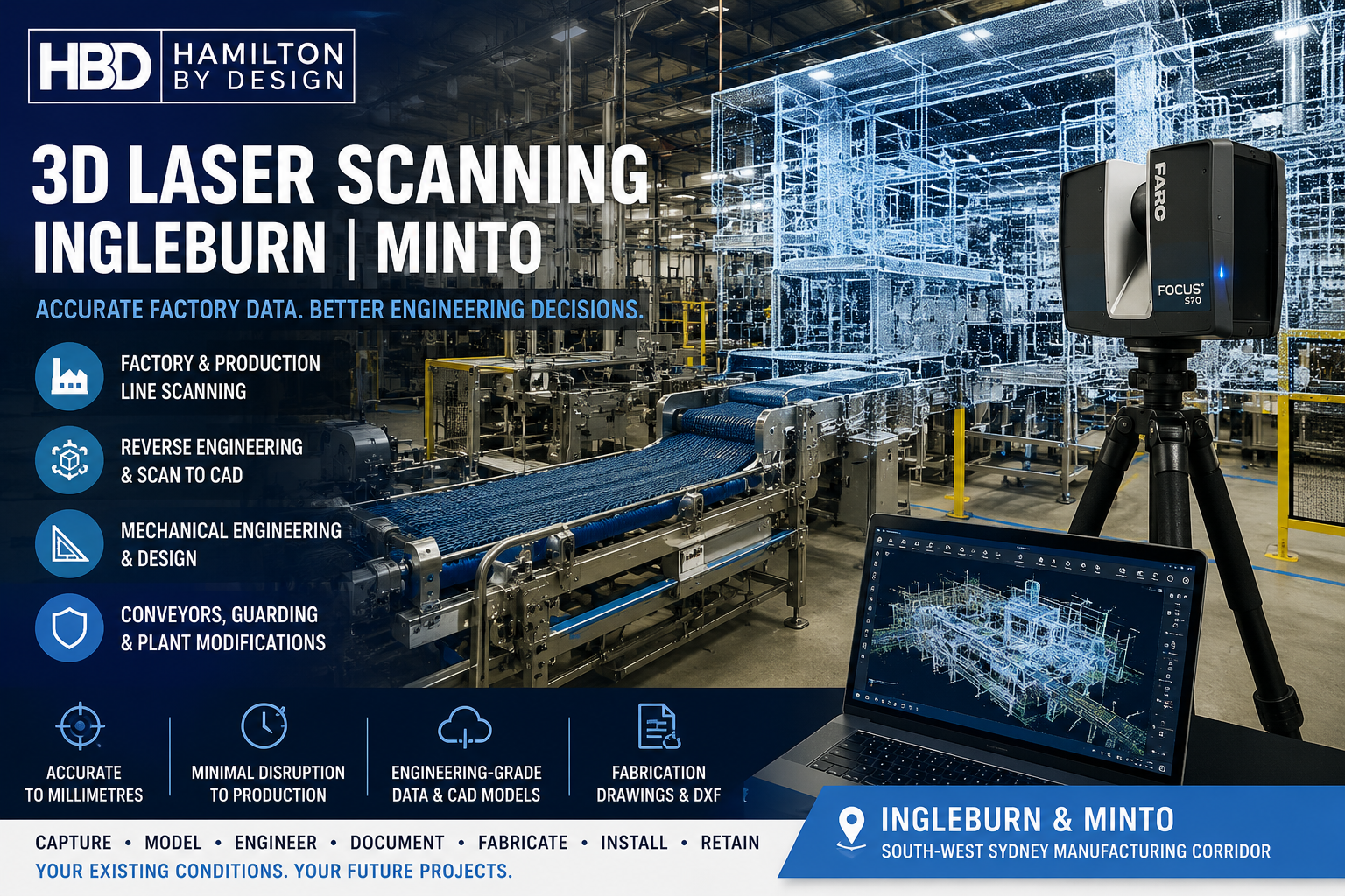


Related Hamilton By Design Engineering Services


Mechanical Engineering Services

Plant upgrades, machinery modifications, equipment integration and practical mechanical engineering support.

View Service โ†’

3D Laser Scanning & Reality Capture

Accurate existing-condition data where drawings are missing, outdated or unreliable.

View Service โ†’

Reverse Engineering

Obsolete or undocumented equipment can be reconstructed, modified or reproduced.

View Service โ†’

Scan-to-CAD / Point Cloud to CAD

Point-cloud information can be converted into usable CAD models and engineering drawings.

View Service โ†’

CAD Design & 3D Modelling

Concepts, sketches or scan data can be developed into detailed manufacturable 3D models.

View Service โ†’

Finite Element Analysis โ€“ FEA

Stress, deflection, fatigue, buckling, vibration and structural performance can be assessed.

View Service โ†’

Machine Guarding Design & Verification

Machinery and conveyor guarding can be designed, modified or engineering-reviewed.

View Service โ†’

Manufacturing & Production Engineering

Production lines and machinery can be integrated, modified or upgraded with minimal disruption.

View Service โ†’

Secondment Engineering Services

Additional engineering capacity for shutdowns, projects, site work or temporary vacancies.

View Service โ†’

Mechanical Drafting

Workshop-ready drawings for manufacturing, installation or plant modification.

View Service โ†’

Australian Design Drafting Services

Mechanical, structural and industrial drafting support for engineering and fabrication projects.

View Service โ†’

Construction Vibration Monitoring

Independent vibration measurement and documentation near buildings and infrastructure.

View Service โ†’

Mechanical Engineering Services

Plant upgrades, machinery modifications, equipment integration and practical mechanical engineering support.

View Service โ†’

3D Laser Scanning & Reality Capture

Accurate existing-condition data where drawings are missing, outdated or unreliable.

View Service โ†’

Reverse Engineering

Obsolete or undocumented equipment can be reconstructed, modified or reproduced.

View Service โ†’

Scan-to-CAD / Point Cloud to CAD

Point-cloud information can be converted into usable CAD models and engineering drawings.

View Service โ†’

CAD Design & 3D Modelling

Concepts, sketches or scan data can be developed into detailed manufacturable 3D models.

View Service โ†’

Finite Element Analysis โ€“ FEA

Stress, deflection, fatigue, buckling, vibration and structural performance can be assessed.

View Service โ†’

Machine Guarding Design & Verification

Machinery and conveyor guarding can be designed, modified or engineering-reviewed.

View Service โ†’

Manufacturing & Production Engineering

Production lines and machinery can be integrated, modified or upgraded with minimal disruption.

View Service โ†’

Secondment Engineering Services

Additional engineering capacity for shutdowns, projects, site work or temporary vacancies.

View Service โ†’

Mechanical Drafting

Workshop-ready drawings for manufacturing, installation or plant modification.

View Service โ†’

Australian Design Drafting Services

Mechanical, structural and industrial drafting support for engineering and fabrication projects.

View Service โ†’

Construction Vibration Monitoring

Independent vibration measurement and documentation near buildings and infrastructure.

View Service โ†’

3D Laser Scanning Ingleburn | Factory & Production Line Scanning

3D laser scanning Ingleburn and Minto factory production line using FARO scanning for reverse engineering, scan-to-CAD and mechanical engineering.
Blue 3D LiDAR scanner icon on a tripod with scanning waves

Ingleburn and Minto form one of South-West Sydneyโ€™s major manufacturing and industrial corridors, supporting food production, machinery manufacturing, metal fabrication, processing equipment, warehousing and established industrial plant.

For many of these facilities, the engineering challenge is not necessarily designing a new machine, conveyor or guard. The greater difficulty is accurately understanding the factory and equipment that the new design must connect to.

Production lines evolve over time. Machines are moved, conveyors are extended, guarding is replaced, structural supports are altered and services are rerouted. After years of incremental modification, the physical factory may differ substantially from the original engineering drawings.

Hamilton By Design provides 3D laser scanning in Ingleburn and Minto to capture these existing conditions and convert them into useful engineering information for production-line modifications, machinery upgrades, reverse engineering and fabrication.

Unlike conventional site measuring, 3D scanning can capture the machinery together with the surrounding factory environment, creating a detailed digital reference that engineers can continue using after leaving site.

For broader industrial applications across Sydney, see our Industrial 3D Scanning Sydney services.


The Biggest Engineering Problem in an Established Factory

A recurring problem within established manufacturing facilities is that the equipment exists physically, but accurate engineering information describing it may not.

A production line may incorporate equipment installed by several manufacturers over many years. Some components may have been locally fabricated, others modified during maintenance shutdowns, and some may no longer be supported by their original manufacturer.

Existing drawings may therefore be:

  • incomplete;
  • obsolete;
  • unavailable;
  • based on superseded machinery arrangements;
  • missing previous plant modifications; or
  • unsuitable for the engineering work now required.

This creates risk when planning a new machine, conveyor, platform, guard or processing system.

Traditional tape measurements can determine individual dimensions, but interconnected production equipment often contains hundreds of spatial relationships. The position of one support frame may affect a conveyor. The conveyor may affect guarding. The guarding may influence maintenance access, while nearby pipework or electrical services may restrict the available installation envelope.

The fundamental question becomes:

How can a plant modification be accurately engineered without repeatedly stopping production to measure the factory?

Engineering-led 3D laser scanning provides one answer.


3D Laser Scanning for Ingleburn and Minto Factories

A terrestrial laser scanner captures millions of measured points from visible surfaces throughout an industrial environment.

These measurements form a 3D point cloud, representing machinery, structures, conveyors, floors, platforms and other surrounding infrastructure in their actual installed positions.

For an Ingleburn manufacturing project, the scan might capture:

  • production machinery;
  • conveyor systems;
  • processing equipment;
  • structural columns and frames;
  • platforms and stairs;
  • machine guarding;
  • pipework;
  • walls and floors;
  • equipment foundations;
  • access areas;
  • neighbouring machinery; and
  • interfaces between old and proposed equipment.

Rather than attempting to manually document every dimension during a short site visit, the project team has a measurable digital reference that can subsequently be reviewed from the office.

Hamilton By Designโ€™s broader 3D Reality Capture Services explain how reality-capture data can support engineering, design and verification workflows.


Production-Line Scanning Before Factory Modifications

Production-line modifications can be particularly difficult because the machinery rarely operates independently.

A relatively small change to a conveyor may affect several adjacent systems.

For example, installing a replacement conveyor could involve:

  • determining existing conveyor centre lines;
  • identifying discharge and receiving equipment;
  • checking pulley and drive locations;
  • measuring available headroom;
  • reviewing structural supports;
  • checking guarding clearances;
  • confirming maintenance access;
  • determining available installation space; and
  • identifying potential clashes with existing equipment.

Scanning the production area creates a common geometric reference against which the proposed modification can be developed.

The objective is not necessarily to model the entire factory in CAD. Instead, Hamilton By Design can identify and model the geometry relevant to the engineering task.

This targeted approach can reduce unnecessary modelling while retaining sufficient site information to understand the surrounding plant.


From Point Cloud to Engineering CAD

A point cloud is extremely useful for understanding existing conditions, but mechanical engineering normally requires structured CAD geometry.

Hamilton By Design can convert selected parts of the scan into usable CAD models and drawings.

Our Point Cloud to AutoCAD workflow can support the development of:

  • equipment layouts;
  • factory plans;
  • structural reference geometry;
  • machine positions;
  • conveyor layouts;
  • equipment interfaces;
  • existing-condition drawings; and
  • plant modification documentation.

Depending on the project, deliverables may also include SolidWorks, Inventor, STEP, SAT, Parasolid, DWG or DXF information.

The important difference is that CAD modelling can be developed directly against measured factory geometry rather than reconstructed primarily from assumptions.


Reverse Engineering Machinery in Ingleburn

Manufacturing facilities often contain machinery that remains mechanically sound but is no longer well documented.

Original drawings may have disappeared, OEM support may have ended or the machine may have been substantially modified since installation.

This is where reverse engineering in Ingleburn can complement factory scanning.

Hamilton By Design can use scan data, direct measurement and engineering assessment to reconstruct components or assemblies for:

  • replacement;
  • modification;
  • refurbishment;
  • duplication;
  • maintenance planning; or
  • integration with new machinery.

The process can progress from the existing physical asset through to CAD models and, where required, fabrication drawings.

For more specialised applications, see our Reverse Engineering 3D Scanning Sydney capability.

This approach can be particularly valuable for older production equipment where a relatively inexpensive fabricated replacement component may keep a productive machine operating without requiring complete equipment replacement.


Conveyor and Material-Handling Modifications

Conveyors are common throughout food manufacturing, processing, packaging, fabrication and industrial production facilities.

They also frequently become modified over time.

A conveyor may need to be:

  • extended;
  • shortened;
  • relocated;
  • raised or lowered;
  • redirected;
  • integrated with replacement machinery;
  • fitted with new guarding; or
  • redesigned around changed production requirements.

Accurate existing-condition information is particularly useful when modifying conveyors because a small positional error can influence downstream equipment.

Scanning can capture conveyor frames, supports, drives, pulleys, transfer points, surrounding structures and adjacent machinery as one coordinated dataset.

The resulting CAD information can then support new fabrication and installation planning.


Machine Guarding and Access

Factory modifications often create a secondary requirement for new guarding.

Changing a conveyor, moving a machine or altering an access platform may affect existing protective systems even when the machinery itself remains unchanged.

Laser scanning can capture existing guarding geometry together with the machine and surrounding access areas.

This information can assist with:

  • replacement fixed guards;
  • conveyor guarding;
  • machine perimeter guarding;
  • maintenance access;
  • removable panels;
  • support brackets;
  • access platforms; and
  • retrofit guarding arrangements.

Hamilton By Design also provides Machine Guarding Certification and Engineering services where engineering review and guarding documentation form part of the broader plant modification.


Mechanical Engineering After the Scan

The greatest value of 3D scanning is realised when the captured information becomes part of the engineering process.

Hamilton By Design can continue from scanning into mechanical design, CAD modelling and fabrication documentation.

A proposed piece of equipment can be positioned digitally within the scanned factory environment before fabrication begins.

This allows the engineering team to investigate questions such as:

  • Will the proposed machine fit?
  • Does the new conveyor align with the existing transfer point?
  • Is sufficient maintenance clearance available?
  • Will new guarding obstruct an access route?
  • Does the fabrication clash with existing structural steel?
  • Can the assembly physically be installed through the available access?
  • Are existing platforms or supports suitable for the proposed arrangement?

The objective is to identify these issues digitally before they become expensive site problems.

Our broader Engineering Services Sydney capability allows scanning to connect directly with mechanical design and plant-modification work.


Fabrication Documentation from Existing Factory Geometry

Once a design has been developed and checked against the scanned environment, engineering information can be prepared for manufacture.

Depending on the project, this may include:

  • general arrangement drawings;
  • assembly drawings;
  • detail drawings;
  • fabrication drawings;
  • bills of materials;
  • DXF cutting profiles;
  • CAD assemblies; and
  • neutral-format STEP or SAT files.

Hamilton By Designโ€™s CAD Services Sydney can support this transition from measured site conditions to workshop documentation.

The overall process can therefore become:

Scan โ†’ Model โ†’ Engineer โ†’ Check โ†’ Document โ†’ Fabricate โ†’ Install

Rather than several disconnected contractors working from separate interpretations of site conditions, the same measured geometry can remain available throughout the engineering workflow.


Retaining a Digital Engineering Record of the Factory

For established manufacturing facilities, one of the less obvious benefits of 3D laser scanning is the ability to retain the data for future engineering work.

Hamilton By Design can retain project information such as:

  • registered production-line point clouds;
  • equipment layouts;
  • CAD assemblies;
  • conveyor models;
  • guarding geometry;
  • machine interfaces;
  • fabrication drawings; and
  • plant modification records.

This means a scan undertaken for one project may continue providing value during future modifications.

For example, a production line initially scanned for a conveyor replacement may later require:

  • new guarding;
  • another machine;
  • an access platform;
  • structural modifications; or
  • relocation of existing equipment.

Provided the relevant area has not materially changed, the retained dataset gives engineers a reference from which to begin evaluating the next project.

This creates a longer-term engineering cycle:

Capture once โ†’ retain the data โ†’ update where necessary โ†’ reuse for future plant modifications.


3D Laser Scanning Across the Ingleburnโ€“Minto Industrial Corridor

Hamilton By Design can support manufacturing and industrial facilities throughout the Ingleburn and Minto area, including nearby industrial locations across South-West Sydney.

Typical projects may involve:

  • food and beverage production;
  • industrial machinery;
  • fabrication facilities;
  • packaging equipment;
  • manufacturing plants;
  • processing equipment;
  • conveyors;
  • warehouses containing production equipment; and
  • brownfield industrial upgrades.

For projects where structured CAD models are required after scanning, our Scan to CAD services provide the link between captured site geometry and engineering design.


Frequently Asked Questions

What is 3D laser scanning used for in an Ingleburn factory?

3D laser scanning can capture machinery, conveyors, structural steel, production equipment, factory layouts and surrounding infrastructure. The resulting point cloud can support plant modifications, equipment integration, reverse engineering and fabrication.

Can you scan a production line while the factory is operating?

In many circumstances, yes. The practical scanning strategy depends on site access, machinery movement, safety requirements and the surfaces that need to be captured. Some areas may require controlled access or short production pauses.

Can the scan be converted into SolidWorks or AutoCAD?

Yes. Relevant areas of a point cloud can be converted into structured CAD geometry using platforms such as SolidWorks, AutoCAD or Inventor. Neutral formats such as STEP and SAT can also be supplied where appropriate.

Do you need to model the entire factory?

No. For most engineering projects, only the geometry relevant to the modification needs to become CAD. The wider point cloud can remain available as contextual information.

Can 3D scanning help with reverse engineering obsolete equipment?

Yes. Scanning, conventional measurement and mechanical engineering can be combined to reconstruct poorly documented or obsolete equipment. CAD models and fabrication documentation can then be developed where required.

Can you design conveyors from the scan data?

Yes. Existing conveyors and surrounding factory geometry can be captured and used as the basis for conveyor modifications, extensions, replacements or integration with new production machinery.

Can you also design machine guarding?

Yes. Hamilton By Design can use scanned machinery and conveyor geometry to develop retrofit guarding arrangements, subject to the required engineering and safety assessment.

Can the point cloud be kept for future projects?

Yes. Production-line point clouds, equipment layouts, CAD assemblies, conveyor models and associated engineering documentation can be retained as a digital record for future modifications, provided changes to the physical plant are considered.

What file formats can be supplied?

Depending on project requirements, deliverables may include point-cloud formats such as E57, RCP, RCS or LAS together with CAD formats such as DWG, DXF, STEP, SAT and native engineering models.

Who normally uses 3D laser scanning in manufacturing facilities?

Typical clients include maintenance managers, plant engineers, project engineers, reliability engineers, production managers, machinery suppliers, OEMs and fabricators undertaking upgrades to existing industrial facilities.


Discuss a 3D Laser Scanning Project in Ingleburn or Minto

If you are planning a production-line modification, replacing obsolete machinery, adding conveyors, upgrading guarding or integrating new equipment into an established factory, accurate existing-condition information can significantly reduce uncertainty before fabrication begins.

Hamilton By Design combines 3D laser scanning, reverse engineering, mechanical design, CAD modelling and fabrication documentation within one engineering workflow.

By capturing the actual factory environment and retaining that information as reusable engineering data, future modifications can be developed from measured site conditions rather than outdated drawings or assumptions.

For 3D laser scanning in Ingleburn, reverse engineering in Ingleburn, mechanical engineering in Minto or production-line scanning across South-West Sydney, contact Hamilton By Design to discuss the existing plant, the proposed modification and the engineering information required.


Hamilton By Design logo displayed on a blue tilted rectangle with a grey gradient background

Contact Us – Talk To Us

Name
Would you like us to arrange a phone consultation for you?
Address

Our clients: