Mechanical engineering has always been a balance between creativity and certainty.
Every bracket, frame, chute, or structural support we design must perform under real loads, temperatures, and conditions — often in environments where failure simply isn’t an option.
That’s where Finite Element Analysis (FEA) earns its place as one of the most powerful tools in modern design. It allows engineers to move from assumption to verification — transforming the way we predict, test, and optimise mechanical systems.
What Is FEA — and Why It Matters
FEA divides complex geometry into a network of small, interconnected elements.
By solving the physical equations that govern stress, strain, and displacement across those elements, engineers can predict how a structure behaves under load, vibration, or temperature.
Instead of relying solely on hand calculations or over-built safety factors, FEA provides quantitative insight into performance — letting us see where structures flex, where stress concentrates, and how design choices affect real-world outcomes.
In mechanical engineering, that means fewer prototypes, lower material costs, and far greater design confidence.
1. Static Analysis — The Foundation of Structural Validation
Static linear analysis is the foundation of most FEA work.
It evaluates how a structure responds to steady, time-independent loads such as gravity, pressure, or fixed equipment weight.
Through static analysis, engineers can:
- Visualise stress and displacement distribution across a part or assembly.
- Evaluate safety factors under different loading conditions.
- Check stiffness and material utilisation before fabrication.
- Identify weak points or stress concentrations early in design.
This baseline validation is the difference between a design that “should” work and one that will.
2. Assembly-Level Simulation — Seeing the Whole System
Few machines fail because a single part breaks.
Most failures happen when components interact under load — bolts shear, brackets twist, or welds experience unplanned tension.
FEA allows engineers to simulate entire assemblies, including:
- Contact between parts (bonded, sliding, or frictional).
- Realistic boundary conditions such as bearings, springs, or pinned joints.
- The influence of welds, fasteners, or gaskets on overall performance.
This system-level view helps mechanical engineers design not only for strength, but also for compatibility and reliability across the full structure.
3. Mesh Control — Accuracy Where It Counts
A simulation is only as good as its mesh.
By controlling element size and density, engineers can capture critical detail in stress-sensitive regions like fillets, bolt holes, and weld toes.
Modern FEA tools use adaptive meshing — refining the model automatically in areas of high stress until the solution converges.
That means precise, efficient results without excessive computation time.
4. Thermal-Structural Interaction — When Heat Becomes a Load
Many mechanical systems face thermal as well as mechanical challenges.
Whether it’s ducting in a process plant or hoppers near heat sources, temperature gradients can cause expansion, distortion, or thermal stress.
FEA allows engineers to:
- Model steady-state or transient heat transfer through solids.
- Apply convection, radiation, or temperature boundary conditions.
- Combine thermal and structural analyses to study thermal expansion and thermal fatigue.
Understanding how heat and load combine helps ensure equipment remains stable, safe, and accurate throughout its lifecycle.
5. Modal and Buckling Analysis — Designing Against Instability
Some risks are invisible until they’re simulated.
Vibration and buckling are two of the most overlooked — yet most common — causes of structural failure.
Modal Analysis
Determines a structure’s natural frequencies and mode shapes, helping designers avoid resonance with operating machinery, fans, or conveyors.
Buckling Analysis
Predicts the critical load at which slender members or thin-walled panels lose stability — allowing engineers to reinforce and optimise designs early.
By identifying these limits before fabrication, engineers can prevent problems that are expensive and dangerous to discover on site.
Design Optimisation — Smarter, Lighter, Stronger
Good design is rarely about adding material; it’s about using it wisely.
FEA supports parametric and goal-based optimisation, enabling engineers to vary geometry, thickness, or material and automatically test multiple configurations.
You can set objectives such as:
- Minimising weight while maintaining strength.
- Reducing deflection under fixed loads.
- Optimising gusset or flange size for stiffness.
This process of “digital lightweighting” drives better performance and cost efficiency — especially valuable in industries where both material and downtime are expensive.
7. Communication and Confidence
FEA isn’t only a calculation tool — it’s a communication tool.
Colour-coded plots, animations, and automated reports make it easier to explain complex mechanical behaviour to project managers, clients, or certifying bodies.
Clear visuals turn stress distributions and displacement fields into a shared language — helping stakeholders understand why certain design choices are made.
Real-World Applications Across Mechanical Engineering
| Application | Type of Analysis | Key Benefit |
|---|---|---|
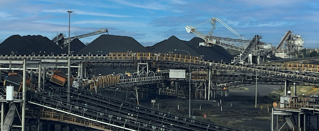
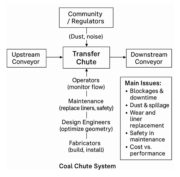
| Chutes & Hoppers | Static + Buckling | Confirm wall thickness and frame design for structural load and vibration |
| Conveyor Frames | Modal + Static | Avoid resonance and ensure adequate stiffness |
| Pressure Equipment | Thermal + Static | Evaluate thermal stress and hoop stress under load |
| Machine Brackets | Static + Optimisation | Reduce weight while maintaining rigidity |
| Platforms & Guarding | Buckling | Validate stability under safety loading |
| Welded Frames & Supports | Static | Check deformation, stress, and weld performance |
These examples show how FEA becomes an everyday design partner — embedded in the workflow of mechanical engineers across manufacturing, resources, and infrastructure.
The Engineer’s Advantage: Data Over Assumption
In traditional design, engineers often relied on prototypes and conservative safety factors.
Today, simulation delivers the same assurance — without the waste.
By applying FEA early in the design cycle, mechanical engineers can:
- Predict failure modes before they occur.
- Shorten development time.
- Reduce material usage.
- Justify design decisions with quantitative proof.
FEA enables engineers to focus less on guesswork and more on innovation — designing structures that are both efficient and dependable.
Engineering Integrity in Practice
At Hamilton By Design, we integrate FEA into every stage of mechanical design and development.
It’s how we ensure that every frame, chute, and mechanical system we deliver performs as intended — safely, efficiently, and reliably.
We use FEA not just to find the limits of materials, but to push the boundaries of design quality — delivering engineering solutions that last in the toughest industrial environments.
Design backed by data isn’t a slogan — it’s how we engineer confidence.
Building a Culture of Verified Design
When FEA becomes part of everyday engineering culture, it changes how teams think.
Designers begin to see structures not just as drawings, but as living systems under real forces.
That shift builds trust — between engineer and client, between concept and reality.
It’s what defines the future of mechanical design: informed, optimised, and proven before the first bolt is tightened.