In today’s construction and industrial environment, the gap between what was designed and what actually exists on site is where most project risk lives.

Steel doesn’t sit where drawings say it should. Pipework clashes with new installs. Structural tolerances stack up. And when projects move fast, those risks become expensive.
This is where engineering-led 3D scanning and design changes everything.
At Hamilton By Design, we don’t just capture data — we convert reality into accurate, buildable engineering outcomes.
The Shift from Measuring to Reality Capture
Traditional site measurement methods rely on tape measures, total stations, and assumptions. They work — but they introduce risk.
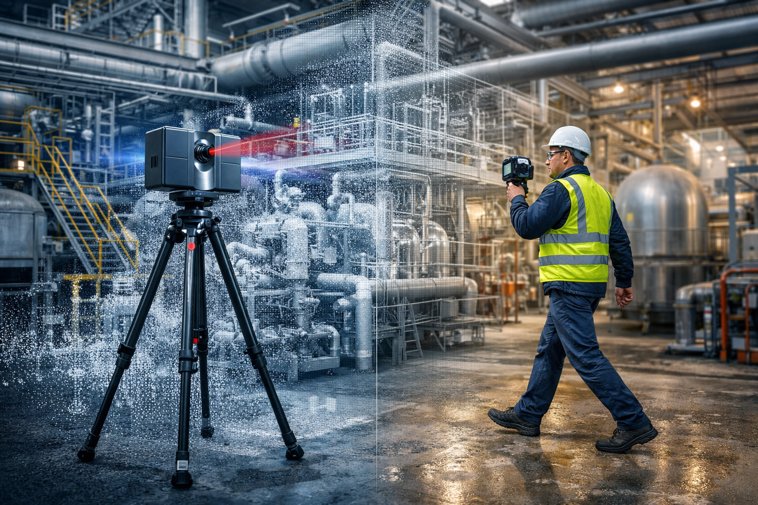
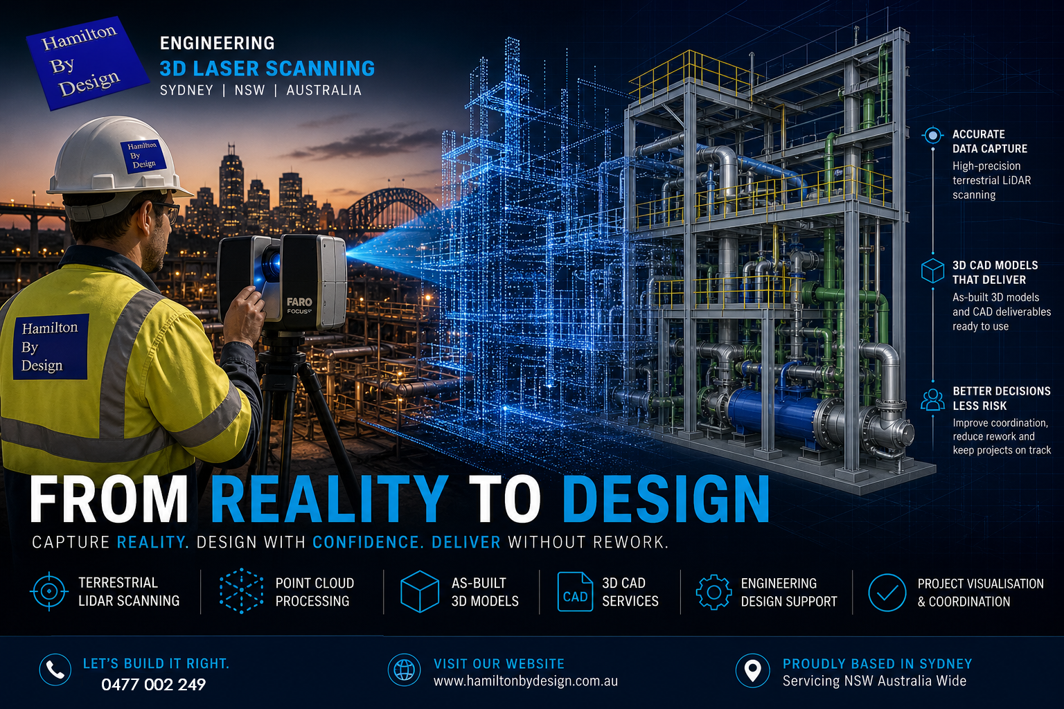
Modern projects are moving toward terrestrial LiDAR scanning, using high-accuracy laser-based systems to capture millions of data points across a site.
A terrestrial LiDAR scanner works by emitting laser pulses and measuring the return time to build a precise 3D representation of the environment — known as a point cloud.
This process, often referred to as a terrestrial scan, creates a true digital record of:
- Structural steel
- Pipework systems
- Equipment layouts
- Buildings and facades
- Complex plant geometry
The result is not an interpretation — it is reality.
From Point Cloud to As-Built 3D Model
Capturing data is only the first step.
The real value comes from converting that scan into an as-built 3D model that engineers, designers, and fabricators can actually use.
This is where many providers fall short.
At Hamilton By Design, we deliver:
- Engineering-grade 3D CAD services
- Parametric models (not mesh files)
- Fabrication-ready geometry
- Drawings aligned to Australian standards
We don’t produce STL or OBJ files that sit unused.
We produce editable 3D engineering design models that integrate directly into your workflow.
Because ultimately — scanning is not the deliverable.
Design is.
3D Scanning on Construction Sites
The use of 3D scanning on construction sites is growing rapidly — and for good reason.
Projects across Sydney are using LiDAR to:
- Verify structural installation before fit-up
- Coordinate mechanical and piping systems
- Reduce rework during shutdowns
- Validate contractor work against design intent
- Capture existing conditions for upgrades
Whether it’s a building scan, plant upgrade, or infrastructure project, the ability to see the full site in 3D changes how teams make decisions.
Instead of relying on drawings — teams work from reality.
Top 3D Scanning Platforms for Project Coordination
Not all scanning workflows are equal.
The top 3D scanning platforms for construction site visualisation and project coordination combine accurate capture with accessible data environments.
Typical platforms include:
- FARO SCENE for registration and processing
- Autodesk ReCap for cloud-based coordination
- 3DEXPERIENCE for engineering governance and collaboration
However, the platform is only part of the equation.
Without engineering understanding, even the best software becomes a viewer — not a solution.
That’s why our workflow is built around:
Scan → Model → Design → Deliver
Engineering-Led 3D Design
What sets Hamilton By Design apart is simple:
We are a mechanical engineering business first — not a scanning company.
Our team uses LiDAR to support:
- 3D design engineering
- Structural modifications
- Conveyor and chute design
- Pipework upgrades
- Equipment integration
We scan with the intent of answering one question:
👉 Will it fit?
Because in engineering — that’s what matters.
Why “3D Scanner Service Near Me” Isn’t Enough
Many clients search for a “3D scanner service near me” or look at 3D scanner hire as a cost-saving measure.
But scanning hardware alone does not solve engineering problems.
Without:
- Proper scan planning (line of sight, density, coverage)
- Registration accuracy
- Engineering interpretation
- CAD modelling capability
…the result is just raw data.
We often see projects where scanning was completed — but nothing usable was produced.
That’s why we offer both:
- Full 3D scan services
- 3D scanner hire (with guidance)
- End-to-end modelling and design support
Applications Across Buildings and Industry
Our 3D scanning building services and industrial workflows support a wide range of sectors across Sydney and NSW:
Construction & Buildings
- As-built verification
- Facade capture
- Structural coordination
- Scan-to-BIM workflows
Industrial Plants
- Brownfield upgrades
- Shutdown planning
- Equipment replacement
- Pipe routing and clash detection
Infrastructure
- Rail and transport assets
- Utilities and pump stations
- Structural assessments
Whether it’s a commercial building or a complex processing plant, the principle is the same:
Capture reality. Design with confidence. Deliver without rework.
The Future: Digital Engineering Driven by LiDAR
LiDAR is not just a tool — it is the foundation of modern digital engineering design.
As projects become more complex, the ability to:
- Capture accurate site data
- Build reliable 3D models
- Coordinate across teams
- Maintain a single source of truth
…will define successful delivery.
At Hamilton By Design, we combine:
- Terrestrial LiDAR scanning
- 3D CAD services
- Engineering design expertise
to ensure that what gets built — matches what was intended.


Work With an Engineer-Led 3D Scanning Team
If you’re planning a project in Sydney or across NSW and need:
- A 3D scan service
- An as-built 3D model
- 3D engineering design support
we’re ready to help.
Because the difference between scanning and engineering is simple:
👉 One captures data.
👉 The other delivers outcomes.

Mechanical Engineering | Structural Engineering
Related Sydney Services
Hamilton By Design provides engineering-led 3D scanning, LiDAR scanning, mechanical engineering and digital engineering services throughout Sydney and Greater Sydney.
Explore our related Sydney services:
- 3D Scanning Sydney – Engineering-grade terrestrial laser scanning, as-built surveys and point cloud capture for industrial, infrastructure and commercial projects.
- Reality Capture Sydney – High-accuracy reality capture, digital twins, asset documentation and engineering-grade site verification.
- Scan to CAD Sydney – Convert point cloud data into AutoCAD, SolidWorks, Inventor and other engineering-ready CAD deliverables.
- Point Cloud Modelling Sydney – Engineering-grade point cloud processing, clash detection, as-built verification and 3D modelling.
- Mechanical Engineering Sydney – Mechanical design, plant upgrades, materials handling systems, conveyors, chutes, platforms and engineering support.
- Structural Drafting Sydney – Structural steel drafting, fabrication drawings, GA drawings, workshop detailing and as-built documentation.
Hamilton By Design supports projects throughout Sydney CBD, Parramatta, Liverpool, Penrith, Blacktown, Chatswood, Alexandria, Mascot, Newcastle and the Central Coast.
Our Clients


Contact Us – Talk to Us – Work with Us