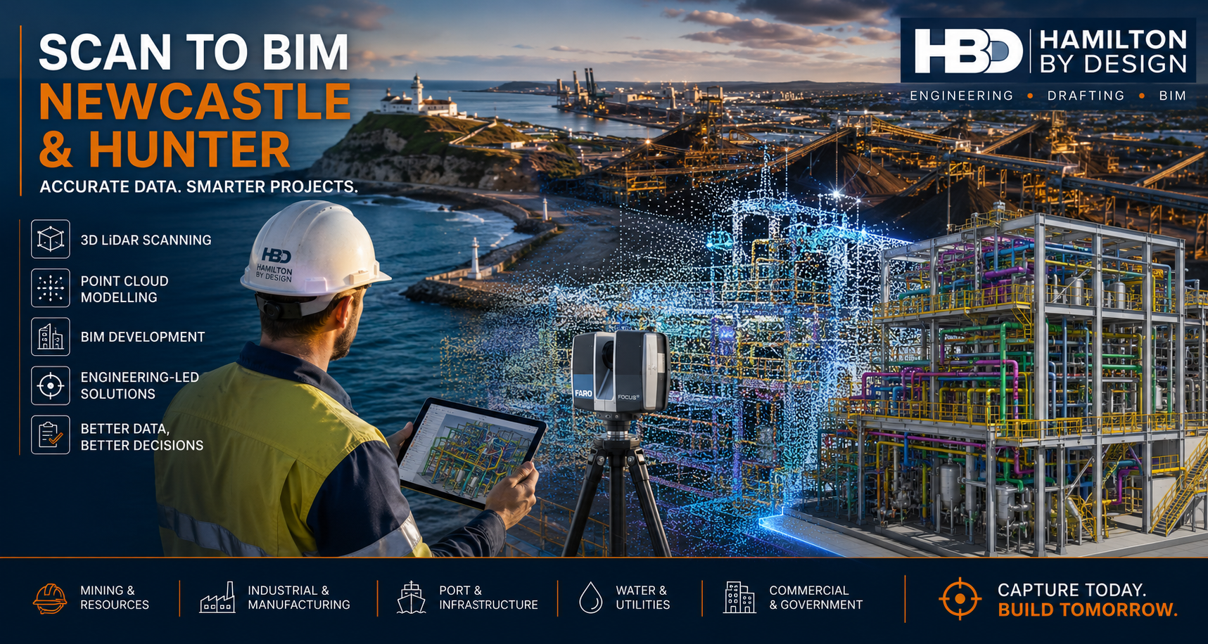
Scan to BIM Newcastle & Hunter | 3D LiDAR Scanning & BIM Modelling
Engineering-Led Scan to BIM Services Across Newcastle, the Hunter Valley and Regional NSW
Hamilton By Design provides professional Scan to BIM Newcastle & Hunter services for industrial, mining, manufacturing, infrastructure, commercial and government projects throughout the region.
Using advanced 3D LiDAR scanning, point cloud processing and BIM modelling technologies, we transform existing buildings, plants and infrastructure into accurate digital models that support engineering, design, construction and asset management workflows.
Whether your project is located in Newcastle CBD, the Port of Newcastle, Kooragang Island, Tomago, Maitland, Singleton, Muswellbrook, Cessnock, Kurri Kurri, Raymond Terrace or the wider Hunter Valley, our engineering-led approach helps deliver accurate information from the very beginning of a project.
Why Scan to BIM is Important for Newcastle & Hunter Projects
The Newcastle and Hunter region is home to some of Australia’s most significant:
- Mining operations
- Coal handling facilities
- Power generation assets
- Manufacturing plants
- Port infrastructure
- Water treatment facilities
- Rail infrastructure
- Heavy industrial sites
- Commercial developments
- Health and education facilities
Many of these assets have been operating for decades.
As facilities evolve, original drawings often become outdated, modifications are undocumented and site conditions differ significantly from available records.
Scan to BIM provides a reliable method of capturing existing conditions before design, construction or upgrade work begins.
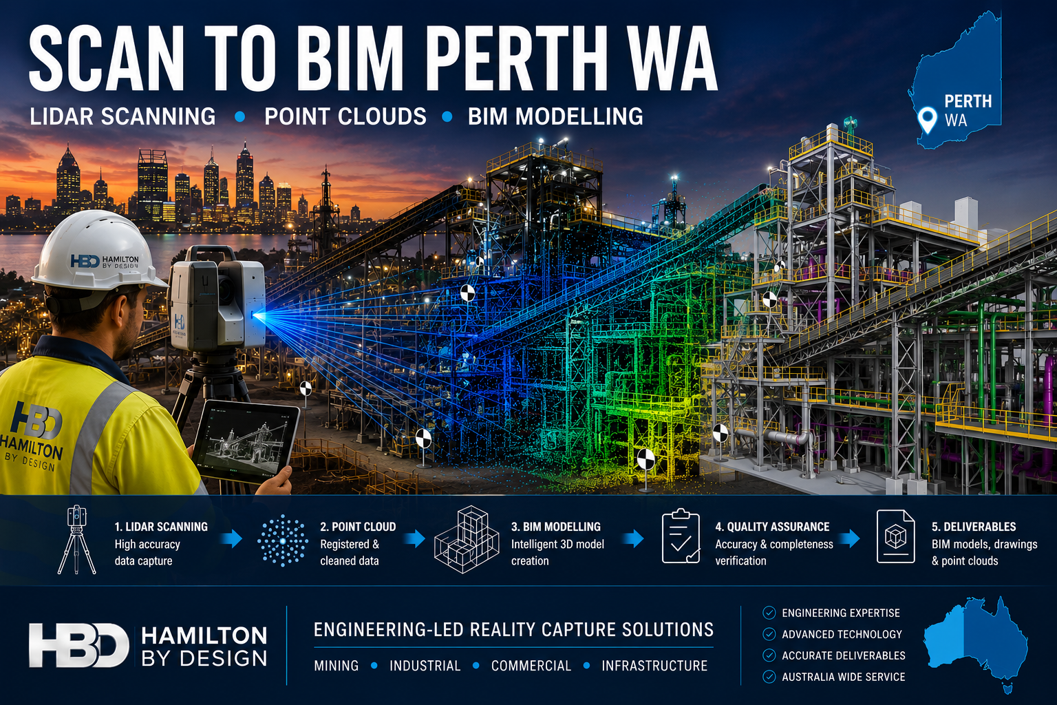
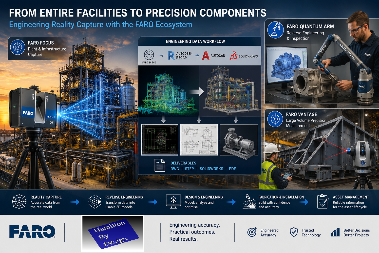
What is Scan to BIM?
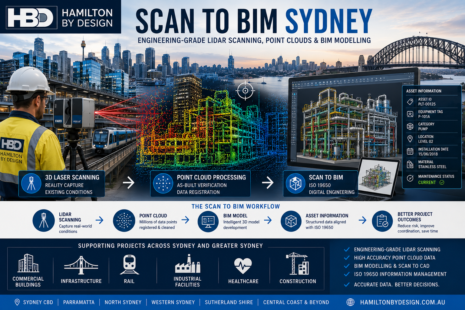
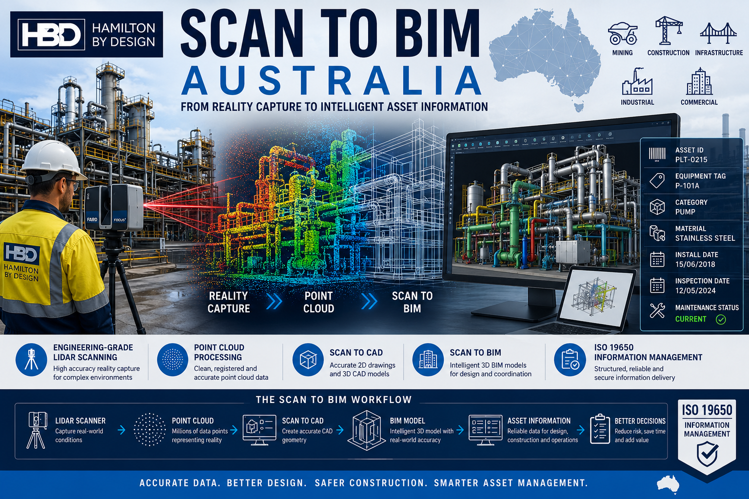
Scan to BIM is the process of converting high-accuracy 3D laser scan data into intelligent BIM models and engineering documentation.
The workflow typically includes:
Stage 1 – Site Capture
Using professional 3D LiDAR scanning equipment, millions of measurements are collected across the site.
The result is a highly detailed digital representation of existing conditions.
Stage 2 – Point Cloud Registration
Individual scans are aligned and registered into a unified coordinate system.
This creates an accurate point cloud representing the entire site.
Stage 3 – BIM Development
The point cloud is converted into BIM models, CAD drawings or digital engineering deliverables suitable for project requirements.
Stage 4 – Engineering Integration
The resulting information can be used for:
- Design development
- Asset management
- Refurbishment projects
- Structural modifications
- Mechanical upgrades
- Clash detection
- Construction planning
- As-built documentation
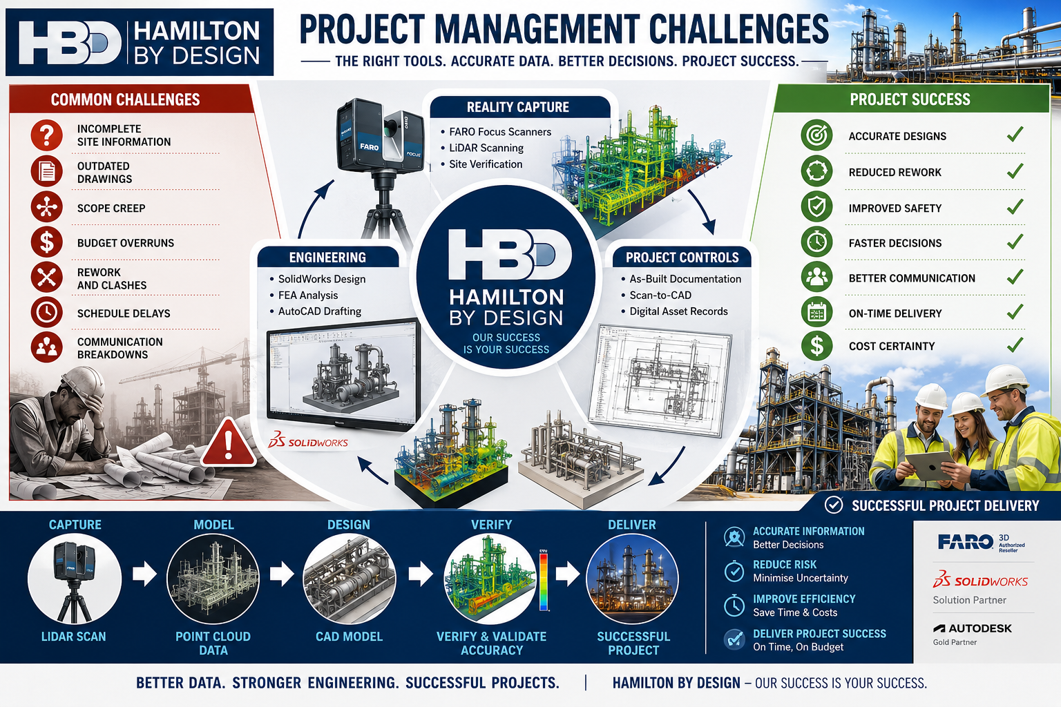
Engineering-Led Site Capture
Hamilton By Design is not simply a scanning provider.
We are mechanical engineering, drafting and design professionals who understand how the information will be used downstream.
This distinction is important.
Many scanning providers deliver a point cloud and leave interpretation to the client.
Our engineering-led approach focuses on creating deliverables that support:
- Mechanical engineering
- Structural engineering
- Plant upgrades
- Access system design
- Fabrication projects
- Shutdown planning
- Asset management
The result is information that can be used immediately by engineers, designers, fabricators and project teams.
Scan to BIM for Mining Operations
The Hunter Valley remains Australia’s largest coal-producing region.
Mining operations continually require:
- Conveyor upgrades
- Transfer chute modifications
- Structural upgrades
- Processing plant improvements
- Materials handling projects
- Shutdown planning
- Asset inspections
Scan to BIM allows project teams to capture existing conditions before engineering begins.
Benefits include:
- Reduced site revisits
- Improved design accuracy
- Better project planning
- Improved safety outcomes
- Reduced rework during installation
For active mining sites, accurate digital information significantly reduces project risk.
Scan to BIM for Manufacturing Facilities
The Newcastle and Hunter region hosts a diverse manufacturing sector including:
- Food processing
- Packaging
- Steel fabrication
- Chemical processing
- Industrial manufacturing
- Warehousing and logistics
Plant modifications often occur within operational facilities where downtime is expensive.
Scan to BIM provides:
- Existing plant layouts
- Equipment locations
- Pipe routing verification
- Structural verification
- Access and maintenance assessments
This information supports more efficient project execution and improved design coordination.
Port and Infrastructure Applications
The Port of Newcastle and associated industrial infrastructure continue to undergo significant upgrades and maintenance programs.
Scan to BIM is ideally suited for:
- Port facilities
- Ship loading infrastructure
- Bulk materials handling systems
- Rail infrastructure
- Water treatment assets
- Industrial terminals
- Civil infrastructure
Accurate digital twins improve planning and reduce uncertainty before construction activities commence.
Scan to BIM Deliverables
Depending on project requirements, Hamilton By Design can provide:
Point Cloud Deliverables
- E57 Files
- LAS Files
- RCP Files
- RCS Files
- Registered point clouds
BIM Deliverables
- Revit Models
- BIM Coordination Models
- Existing Condition Models
- Architectural Models
- Structural Models
- Mechanical Models
CAD Deliverables
- AutoCAD Drawings
- Floor Plans
- Sections
- Elevations
- General Arrangement Drawings
- Fabrication Support Models
Engineering Deliverables
- Plant Layout Models
- Equipment Models
- Structural Steel Models
- Access Platform Designs
- Mechanical Engineering Documentation
Brownfield Engineering Projects
Most projects throughout Newcastle and the Hunter are brownfield projects.
These sites often present challenges including:
- Missing drawings
- Incomplete records
- Historic modifications
- Access restrictions
- Complex service routes
Scan to BIM significantly reduces uncertainty by creating an accurate representation of existing conditions.
This allows project teams to design around real-world constraints rather than assumptions.
Digital Engineering and Asset Management
Beyond design and construction, Scan to BIM supports long-term asset management.
Benefits include:
- Accurate asset records
- Improved maintenance planning
- Digital twin development
- Lifecycle management
- Future project planning
- Improved facility documentation
As infrastructure owners increasingly adopt digital engineering strategies, accurate existing-condition models become a valuable long-term asset.
Why Choose Hamilton By Design?
Hamilton By Design combines:
- Engineering expertise
- 3D LiDAR scanning
- Mechanical design
- Structural drafting
- BIM development
- CAD modelling
- Industrial project experience
Our team understands both the technology and the engineering outcomes required by clients.
This allows us to provide practical solutions that support project delivery rather than simply producing scan data.
Areas We Service
We support projects across:
- Newcastle
- Hunter Valley
- Maitland
- Singleton
- Muswellbrook
- Kurri Kurri
- Cessnock
- Raymond Terrace
- Port Stephens
- Lake Macquarie
- Kooragang Island
- Tomago
- Central Coast
- Upper Hunter
- Mid North Coast
We also regularly support clients throughout regional NSW and interstate.

Need a Scan to BIM Newcastle & Hunter Quote?
If you require accurate existing-condition information for an upcoming engineering, construction, mining or industrial project, Hamilton By Design can help.
Our Scan to BIM services provide reliable digital information that supports better decision-making, improved design outcomes and reduced project risk.
Contact Hamilton By Design today to discuss your Scan to BIM Newcastle & Hunter project.
Talk to Us – Contact Us
Our clients: