3D Scanning and Mechanical Engineering Services Kwinana WA

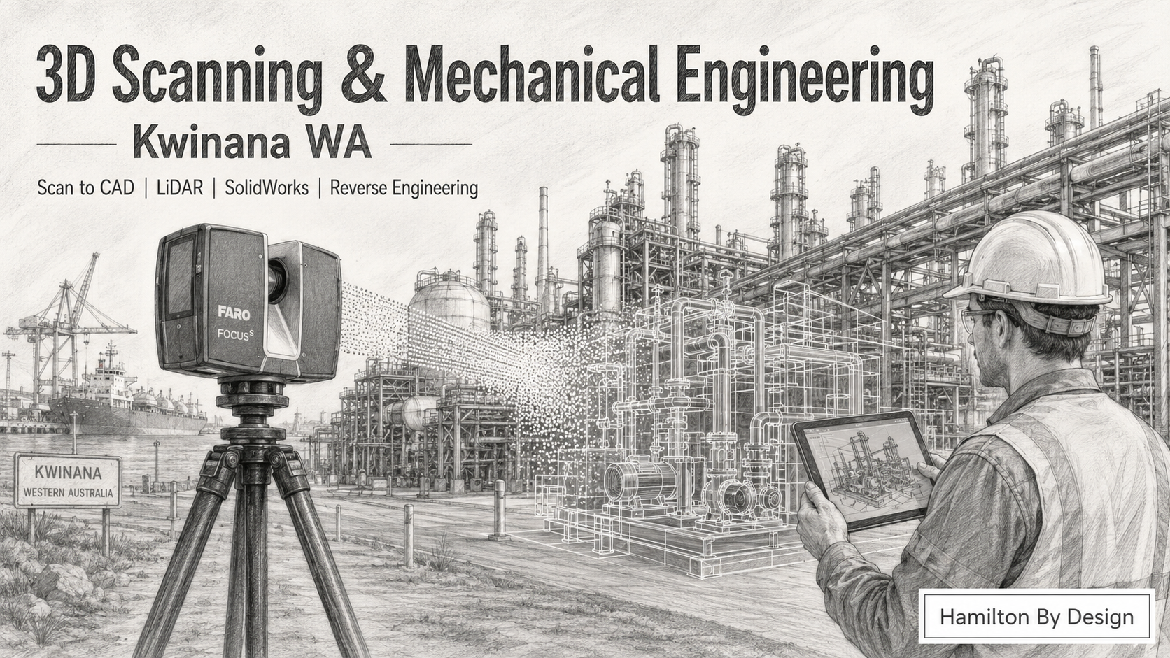
Pencil drawing of 3D scanning and mechanical engineering services in Kwinana WA, showing a FARO laser scanner, point cloud, industrial plant, CAD overlay and engineer with tablet.

Engineer-Led 3D Scanning and Mechanical Design Support for Kwinana Industry

Blue 3D LiDAR scanner icon on a tripod with scanning waves

Hamilton By Design provides 3D scanning and mechanical engineering services in Kwinana WA for industrial plants, processing facilities, workshops, fabrication companies, maintenance teams and project engineers.

Kwinana is one of Western Australiaโ€™s most important industrial areas. It supports heavy industry, bulk handling, energy, minerals processing, chemical processing, fabrication, marine services, port infrastructure and industrial maintenance. In these environments, accurate site information is essential. When existing drawings are missing, outdated or unreliable, engineering decisions become harder, slower and more expensive.

That is where 3D laser scanning, LiDAR capture and mechanical engineering design support can help.

Hamilton By Design combines site-based 3D scanning, point cloud processing, SolidWorks modelling, mechanical drafting and reverse engineering to help Kwinana businesses understand existing plant conditions before they design, modify, fabricate or install new equipment.

Whether you need accurate site measurements, as-built documentation, Scan to CAD, reverse engineering of obsolete parts, equipment layout verification or mechanical design support, we can help turn real-world site conditions into useful engineering information.

Why 3D Scanning Matters for Kwinana Industrial Sites

Industrial sites in Kwinana often contain complex plant, pipework, tanks, conveyors, platforms, structural steel, access systems, mechanical equipment and services that have changed over many years.

The problem is simple: the drawings do not always match the site.

A plant may have been modified during shutdowns. Pipework may have been rerouted. Platforms may have been added. Equipment may have been replaced. Fabricators may have worked from site measurements instead of updated drawings. Over time, the real site and the drawing register can become very different.

For brownfield projects, this creates risk.

A new chute may clash with existing steel. A replacement pump base may not line up with the real hold-down bolt locations. A platform may interfere with pipework. A new mechanical assembly may fit in CAD but fail during installation because the design was based on old information.

3D scanning reduces this risk by capturing the existing site in accurate three-dimensional detail. Instead of relying only on manual tape measurements, photos and old drawings, project teams can work from a measured point cloud of the real plant.

Common Problems We Help Solve

Hamilton By Design supports Kwinana industrial businesses with practical engineering information for real-world problems.

Common issues include:

  • Existing drawings are missing, outdated or incomplete
  • New equipment may clash with existing plant
  • Fabrication drawings are required before a shutdown
  • OEM drawings are unavailable
  • Replacement parts are expensive or have long lead times
  • Manual site measurements are difficult, unsafe or incomplete
  • Access platforms, stairs and handrails need to fit around existing equipment
  • Pipework, conveyors, tanks or structures need to be modelled from site data
  • Plant upgrades need accurate as-built information
  • Project teams need better information before approving fabrication

When the plant is complex, old or heavily modified, 3D scanning provides a better starting point.

3D Laser Scanning Services in Kwinana WA

Our 3D scanning service is designed for industrial environments where accurate measurement matters.

We can scan:

  • Processing plants
  • Pump stations
  • Conveyor systems
  • Chutes and hoppers
  • Structural steel
  • Pipe racks and pipework
  • Tanks and vessels
  • Access platforms
  • Stairs and handrails
  • Maintenance areas
  • Workshops and fabrication spaces
  • Marine and port-related infrastructure
  • Brownfield upgrade areas
  • Existing equipment layouts

The scan data can be used for design, verification, planning, fabrication, modelling and project review.

For industrial work, the value is not just the scan itself. The value comes from turning scan data into engineering information that designers, project managers, fabricators and site teams can actually use.

Scan to CAD for Kwinana Industrial Projects

Scan to CAD is the process of converting 3D scan data into CAD models, drawings or design references.

For Kwinana industrial sites, Scan to CAD can be useful when a project team needs a reliable model of existing conditions before designing new work.

Hamilton By Design can convert point cloud data into:

  • SolidWorks models
  • AutoCAD drawings
  • STEP files
  • SAT files
  • DWG files
  • DXF files
  • General arrangement drawings
  • Section views
  • Elevations
  • Fabrication references
  • Mechanical layout models
  • As-built CAD geometry

This is especially useful when working around existing plant, services and structures.

A good Scan to CAD workflow can help answer important questions before fabrication starts:

Will the new equipment fit?

Is there enough clearance?

Are the bolt locations correct?

Will the pipework clash?

Can the platform be installed safely?

Does the model match the real site?

These questions are much cheaper to answer in CAD than during installation.

Mechanical Engineering Services Kwinana WA

Hamilton By Design also provides mechanical engineering and drafting support for Kwinana businesses.

Our mechanical engineering services can include:

  • Mechanical design
  • Equipment layouts
  • Reverse engineering
  • Replacement component modelling
  • Pump and machinery component drawings
  • Fabrication drawings
  • General arrangement drawings
  • Access platform layouts
  • Chute and hopper design support
  • Conveyor-related drafting
  • Pipework drafting support
  • Brownfield modification design
  • Site measurement and verification
  • Engineering-grade CAD modelling

We work with industrial clients who need practical design support that connects the site, the CAD model and the workshop.

This is important because many industrial projects fail at the connection point between design and site reality. A drawing may look correct, but the real plant may tell a different story. By combining 3D scanning with mechanical engineering, the design process starts with better information.

Reverse Engineering for Kwinana Equipment and Parts

Many Kwinana industrial businesses operate equipment where original drawings are unavailable, the OEM no longer supports the part, or replacement lead times are too long.

Reverse engineering can help by measuring the existing component and creating a CAD model or drawing that can support replacement, repair, modification or local manufacture.

Hamilton By Design can assist with reverse engineering of:

  • Pump components
  • Shafts
  • Brackets
  • Guards
  • Covers
  • Frames
  • Mounts
  • Housings
  • Fabricated parts
  • Machined parts
  • Wear components
  • Custom plant items

Depending on the part and project requirement, reverse engineering may involve 3D scanning, manual measurement, CAD modelling, material review, tolerance consideration and production of manufacturing drawings.

This can be useful when an urgent replacement is required, when a part needs to be improved, or when site teams need to reduce reliance on unavailable OEM drawings.

Brownfield Engineering Support

Kwinana contains many brownfield industrial sites where new work must fit around existing infrastructure.

Brownfield work is difficult because there is rarely a clean, empty design space. The design must fit around what is already there.

This may include:

  • Existing structural steel
  • Pipework
  • Electrical services
  • Access ways
  • Platforms
  • Guarding
  • Tanks
  • Conveyors
  • Process equipment
  • Maintenance access zones
  • Crane access
  • Shutdown constraints

3D scanning helps create a digital record of these existing conditions. Mechanical engineering then uses that information to design practical solutions.

This can reduce the risk of rework, installation delays and fabrication changes.

Why Kwinana Businesses Use 3D Scanning Before Fabrication

Fabrication errors can be costly. If steel is fabricated from incorrect dimensions, the problem may not appear until installation. By then, the project may already be in shutdown, cranes may be booked, trades may be waiting and production may be affected.

3D scanning helps avoid this by confirming site conditions before fabrication.

For example, a scan can help check:

  • Existing steel locations
  • Floor levels
  • Equipment footprints
  • Pipework positions
  • Access clearances
  • Tank and vessel locations
  • Conveyor geometry
  • Bolt patterns
  • Existing maintenance access
  • Interface points between old and new equipment

This gives engineers and fabricators more confidence before cutting steel, ordering material or issuing drawings for manufacture.

Deliverables Available

Depending on the project, Hamilton By Design can provide:

  • Point cloud files
  • E57 files
  • RCP / RCS files
  • 3D CAD models
  • SolidWorks models
  • STEP / SAT files
  • DWG / DXF drawings
  • General arrangement drawings
  • Sections and elevations
  • Fabrication drawings
  • Reverse engineering drawings
  • Site verification reports
  • Mechanical design layouts

The right deliverable depends on the project outcome. Some clients need point cloud data. Others need a full CAD model. Some only need key interface geometry for fabrication. We can help define the right level of detail before the work begins.

Industries We Support Around Kwinana

Hamilton By Design can support industrial clients across Kwinana and surrounding areas including Rockingham, Henderson, Naval Base, Hope Valley, Cockburn, Welshpool, Canning Vale, Forrestdale and the broader Perth industrial region.

Relevant industries include:

  • Heavy industry
  • Minerals processing
  • Chemical processing
  • Energy and utilities
  • Bulk materials handling
  • Port infrastructure
  • Marine and defence support
  • Fabrication workshops
  • Mechanical contractors
  • Maintenance teams
  • Industrial construction
  • Processing plants
  • Water and wastewater infrastructure

Why Choose Hamilton By Design

Hamilton By Design is not just a scanning business. We understand mechanical engineering, drafting, fabrication, site measurement and industrial design.

This matters because a point cloud on its own does not solve every problem. The real value comes from knowing what to extract from the scan, what needs to be modelled, what needs to be drawn, and what information the workshop or project engineer needs next.

Our approach is practical:

  1. Capture the existing site conditions
  2. Process the scan data
  3. Review the engineering problem
  4. Convert the information into useful CAD or drawings
  5. Support design, fabrication or installation decisions

This helps clients move from uncertainty to usable engineering information.

3D Scanning and Mechanical Engineering for Kwinana WA

If your Kwinana project depends on accurate site information, Hamilton By Design can help.

We support industrial clients with 3D scanning, LiDAR capture, Scan to CAD, mechanical engineering, reverse engineering and drafting services across Kwinana and the wider Perth industrial region.

Whether you are planning a shutdown, replacing obsolete parts, modifying existing plant, designing new equipment or checking site conditions before fabrication, accurate 3D data can reduce risk and improve project confidence.

Hamilton By Design logo displayed on a blue tilted rectangle with a grey gradient background

Need 3D Scanning or Mechanical Engineering Support in Kwinana?

Talk to Hamilton By Design about your Kwinana industrial project.

We can assist with:

  • 3D laser scanning
  • Scan to CAD
  • Mechanical engineering
  • Reverse engineering
  • SolidWorks modelling
  • Fabrication drawings
  • Brownfield plant upgrades
  • Site verification
  • Industrial drafting

For engineering-grade 3D scanning and mechanical design support in Kwinana WA, contact Hamilton By Design.

Talk to Us – Contact Us

Name
Would you like us to arrange a phone consultation for you?
Address

Our clients:
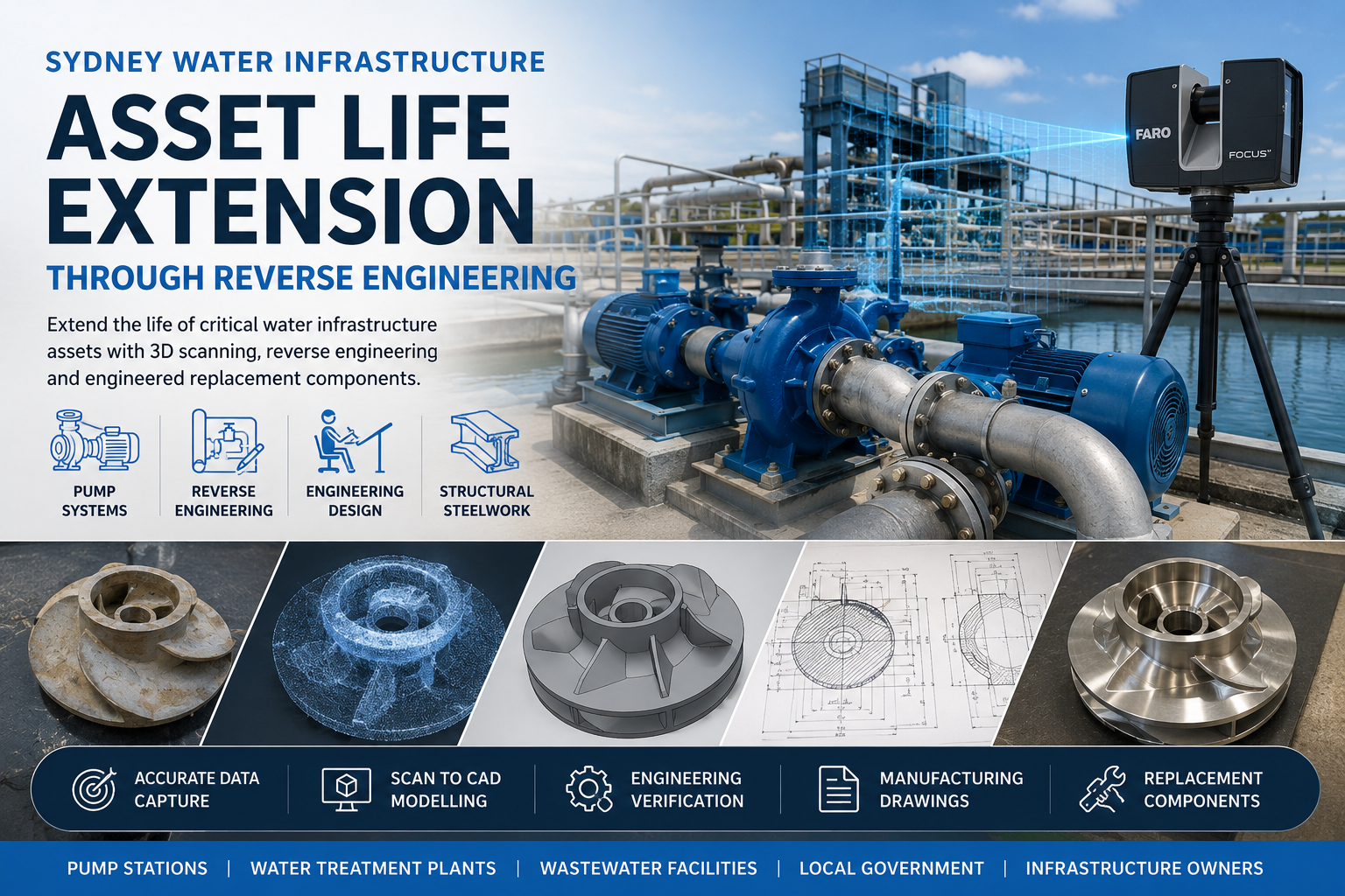


Sydney Water Infrastructure Asset Life Extension Through Reverse Engineering

Sydney water infrastructure asset life extension through reverse engineering, 3D scanning, pump system modelling and replacement component engineering

Extend the Life of Critical Water Infrastructure Assets Across Sydney NSW

Pump and Motor Assembly Icon for Reverse Engineering and Water Infrastructure Engineering Services

Hamilton By Design provides reverse engineering, 3D LiDAR scanning, Scan-to-CAD, engineering design and replacement component development services for water infrastructure assets throughout Sydney NSW. We help water utilities, local government authorities, wastewater treatment facilities, sewer pump stations, power stations and infrastructure operators extend the life of critical assets when OEM support is no longer available, replacement parts are obsolete, original manufacturers no longer exist, or complete asset replacement is prohibitively expensive.

Many water infrastructure assets continue to operate effectively long after original equipment manufacturers have discontinued support. Rather than replacing entire systems, Hamilton By Design uses engineering-grade 3D scanning, reverse engineering and detailed design documentation to recreate components, assemblies and equipment that can no longer be sourced through traditional supply channels.

Our services help asset owners reduce downtime, minimise capital expenditure, improve maintenance planning and extend the operational life of critical infrastructure assets.


Reverse Engineering Solutions for Sydney Water Infrastructure

Water and wastewater infrastructure across Sydney contains thousands of mechanical and structural assets that have been operating for decades. Many of these systems remain structurally sound but are increasingly difficult to maintain due to unavailable spare parts, missing documentation and ageing equipment.

Hamilton By Design specialises in reverse engineering and asset life extension for:

  • Pump Stations
  • Water Treatment Plants
  • Wastewater Treatment Plants
  • Sewer Pump Stations
  • Water Distribution Infrastructure
  • Reservoir Facilities
  • Power Stations
  • Mining Water Infrastructure
  • Mechanical Equipment
  • Structural Steelwork
  • Pipework Systems
  • Valve Assemblies
  • Access Platforms and Walkways

Our engineering-led approach enables clients to maintain existing infrastructure while avoiding unnecessary replacement of complete systems.


Common Challenges Facing Asset Owners

OEM Support Has Been Discontinued

Many infrastructure assets continue operating long after manufacturers cease supporting equipment. Spare parts become difficult or impossible to obtain, creating maintenance challenges and increasing operational risk.

Hamilton By Design can reverse engineer existing components and develop manufacturing documentation for replacement parts when OEM support is no longer available.

Obsolete Replacement Parts

Asset owners frequently encounter situations where pumps, valves, gearboxes, hydraulic systems or structural components remain operational but replacement parts are no longer manufactured.

Using 3D scanning and reverse engineering, we recreate obsolete components from existing assets, worn parts or physical samples.

Original Manufacturers No Longer Exist

Many water infrastructure assets installed decades ago were supplied by manufacturers that have since merged, changed ownership or ceased operations entirely.

Where original design information is unavailable, our engineering team can reconstruct components using physical measurements, laser scanning and engineering analysis.

Missing Drawings and Documentation

Many facilities operate equipment with limited or incomplete documentation. Original drawings may be lost, outdated or unavailable.

Hamilton By Design develops accurate digital engineering documentation including:

  • General Arrangement Drawings
  • Manufacturing Drawings
  • Assembly Drawings
  • Fabrication Drawings
  • 3D CAD Models
  • Asset Records

Long Lead Times for Imported Components

Critical infrastructure often depends on specialised equipment with long procurement lead times.

Reverse engineering can significantly reduce downtime by enabling local manufacture of replacement components rather than waiting months for imported parts.

Asset Replacement Costs Are Prohibitive

Replacing entire systems may involve significant capital expenditure, extensive shutdown periods and operational disruption.

Asset life extension strategies often provide substantial cost savings by replacing only the components that have deteriorated while retaining serviceable infrastructure.


Engineering-Grade 3D LiDAR Scanning

Successful reverse engineering begins with accurate data capture.

Hamilton By Design uses advanced FARO 3D scanning technology to capture precise measurements of existing infrastructure, equipment and plant environments.

Applications include:

  • Pump Stations
  • Treatment Plants
  • Pipework Networks
  • Valve Assemblies
  • Structural Steelwork
  • Mechanical Equipment
  • Brownfield Facilities

Benefits include:

  • Accurate As-Built Information
  • Reduced Site Rework
  • Improved Design Accuracy
  • Faster Engineering Delivery
  • Enhanced Project Planning

Scan-to-CAD and Digital Asset Capture

Following site capture, point cloud data is processed and converted into engineering deliverables suitable for design, maintenance and manufacturing activities.

Deliverables may include:

  • E57 Point Clouds
  • RCP Files
  • RCS Files
  • AutoCAD Models
  • SolidWorks Models
  • STEP Files
  • Parasolid Files
  • DWG Drawings
  • DXF Files

This process provides asset owners with accurate digital records of existing infrastructure for future maintenance and upgrade projects.


Reverse Engineering of Critical Infrastructure Components

Hamilton By Design regularly reverse engineers components that are no longer available through original manufacturers.

Typical components include:

Pump Components

  • Impellers
  • Pump Casings
  • Pump Shafts
  • Wear Rings
  • Mechanical Assemblies

Valve Assemblies

  • Valve Bodies
  • Actuation Components
  • Sealing Systems
  • Mounting Arrangements

Mechanical Equipment

  • Bearing Housings
  • Couplings
  • Gearbox Components
  • Hydraulic Cylinders
  • Rotating Equipment

Structural Infrastructure

  • Access Platforms
  • Walkways
  • Handrails
  • Structural Steelwork
  • Equipment Supports

Process Plant Equipment

  • Pipe Spools
  • Conveyor Components
  • Chute Liners
  • Material Handling Equipment

Engineering Design and Verification

Reverse engineering involves more than reproducing geometry.

Hamilton By Design applies engineering principles to evaluate:

  • Material Selection
  • Structural Performance
  • Manufacturing Methods
  • Operational Requirements
  • Installation Constraints
  • Long-Term Reliability

Where required, Finite Element Analysis (FEA) can be undertaken to assess component performance and identify opportunities for improvement over the original design.

This ensures replacement components are suitable for ongoing operation within demanding infrastructure environments.


Manufacturing Documentation and Deliverables

Following reverse engineering, Hamilton By Design develops manufacturing-ready documentation suitable for fabrication, machining and procurement.

Typical deliverables include:

  • Manufacturing Drawings
  • Fabrication Drawings
  • Assembly Drawings
  • General Arrangement Drawings
  • Bills of Materials
  • CAD Models
  • STEP Files
  • Parasolid Files
  • DWG Files
  • DXF Files
  • Material Specifications
  • Engineering Reports

These deliverables provide asset owners and contractors with the information required to manufacture replacement components accurately and efficiently.


Our Reverse Engineering Process

1. Site Inspection and Asset Assessment

Existing infrastructure is reviewed to determine project requirements, access constraints and available documentation.

2. 3D LiDAR Scanning and Measurement

Engineering-grade scanning captures accurate asset geometry and surrounding infrastructure.

3. Point Cloud Processing

Captured data is registered, validated and prepared for engineering use.

4. Reverse Engineering

Components and assemblies are modelled using SolidWorks and AutoCAD.

5. Engineering Verification

Materials, fitment, functionality and operational requirements are assessed.

6. Manufacturing Documentation

Detailed engineering drawings and models are prepared.

7. Installation and Ongoing Support

Hamilton By Design can provide engineering support during manufacture, installation and commissioning activities.


Supporting Water Utilities and Infrastructure Owners Across Sydney

Hamilton By Design supports organisations responsible for maintaining critical infrastructure throughout Sydney NSW.

Our clients include:

  • Water Utilities
  • Water Treatment Facilities
  • Wastewater Treatment Facilities
  • Local Government Authorities
  • Infrastructure Owners
  • Power Generation Facilities
  • Mining Operations
  • Engineering Consultancies
  • Maintenance Contractors

By combining reverse engineering, 3D LiDAR scanning, engineering design and manufacturing documentation, we help asset owners extend the life of critical infrastructure while reducing replacement costs and operational risk.


Hamilton By Design logo displayed on a blue tilted rectangle with a grey gradient background

Need Assistance Extending the Life of Water Infrastructure Assets?

If your organisation is facing obsolete equipment, missing documentation, discontinued OEM support or long lead times for replacement parts, Hamilton By Design can help.

Our engineering team provides Sydney-based reverse engineering, 3D scanning and asset life extension services designed to keep critical infrastructure operating safely and efficiently.

Contact Hamilton By Design to discuss your water infrastructure asset life extension project.

Talk to Us – Contact Us

Name
Would you like us to arrange a phone consultation for you?
Address

Our clients:


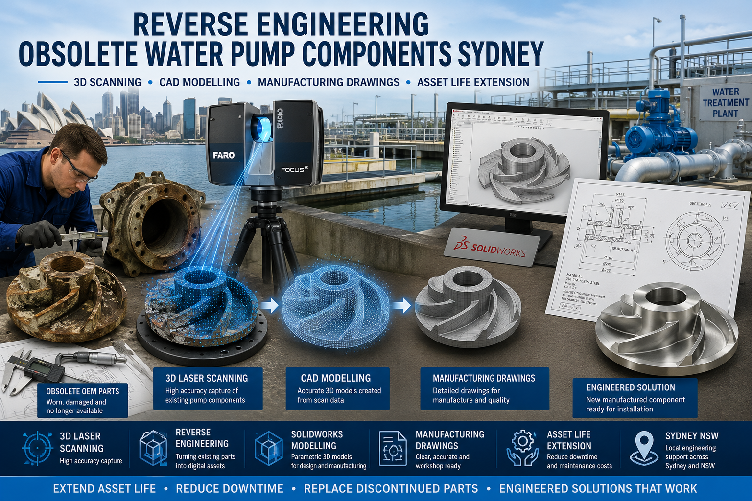
Reverse Engineering Obsolete Water Pump Components Sydney

Reverse engineering obsolete water pump components in Sydney using 3D laser scanning, SolidWorks CAD modelling and manufacturing drawings to replace discontinued OEM pump parts for water infrastructure and industrial facilities.

Reverse Engineering Obsolete Water Pump Components Sydney

Hamilton By Design provides reverse engineering services for obsolete water pump components in Sydney NSW, helping water utilities, maintenance teams, manufacturers, asset owners and engineering contractors replace discontinued OEM pump parts when drawings, models or supplier support are no longer available. We inspect, measure, scan and model existing pump components to create accurate CAD files, manufacturing drawings and engineering documentation suitable for repair, replacement, refurbishment or local manufacture.

Reverse Engineering for Obsolete Pump Components in Sydney NSW

Water pump assets often remain in service for decades. Over time, OEM parts can become unavailable, lead times can increase, suppliers may discontinue product lines, and replacement costs can become difficult to justify. For councils, water treatment plants, pumping stations, industrial facilities and infrastructure operators, this can create serious maintenance and operational risks.

Hamilton By Design supports Sydney-based clients by reverse engineering worn, damaged or obsolete water pump components so they can be reproduced, repaired or improved. This includes pump casings, impellers, shafts, sleeves, bushes, bearing housings, covers, flanges, couplings, wear rings, brackets and other mechanical pump components.

Our work combines practical trade experience, mechanical engineering knowledge, 3D scanning, CAD modelling and detailed drafting. The result is clear, usable documentation that can support fabrication, machining, casting, repair, procurement and asset maintenance.

Who We Help

We provide reverse engineering and engineering drafting services for clients across Sydney NSW and surrounding regions, including:

Water treatment plants
Wastewater facilities
Council pumping stations
Industrial water systems
Utilities and infrastructure operators
Manufacturing plants
Mining and mineral processing facilities
Ports and marine infrastructure
Mechanical contractors
Maintenance teams
Fabricators and machine shops
Pump repair workshops
Asset owners with discontinued OEM equipment

We also support projects in Newcastle, the Hunter Valley, Brisbane, Perth, Melbourne, regional NSW and across Australia where pump components or mechanical assets need to be measured, modelled and documented.

Why Reverse Engineer Obsolete Water Pump Components?

Reverse engineering is useful when an existing component is required but original design information is missing or unreliable. Many older water pump assets were installed years ago, and drawings may no longer exist, may be incomplete, or may not reflect changes made during maintenance.

Reverse engineering can help when:

OEM parts are discontinued
OEM lead times are too long
Replacement parts are too expensive
The original drawings are missing
The part has been modified over time
A casting pattern is no longer available
A pump needs to remain operational
A local manufacturing option is required
The component needs to be improved or strengthened
A damaged part needs to be reproduced urgently

For water infrastructure, downtime can be costly. Reverse engineering allows asset owners to extend the life of critical pump equipment while maintaining control over documentation, repair options and future spare parts.

Typical Pump Components We Reverse Engineer

Hamilton By Design can reverse engineer a wide range of pump and rotating equipment components, including:

Impellers
Pump casings
Bearing housings
Shafts
Shaft sleeves
Wear rings
Bushes
Couplings
Drive components
Flanges
Covers and guards
Mounting brackets
Split casings
Casting components
Machined components
Replacement OEM-style parts
Obsolete water pump components
Custom repair components

Where required, we can also document finished machining details, keyways, fits, tolerances, material notes, surface finish requirements and general arrangement information.

Technical Capability

Our reverse engineering workflow combines physical inspection, 3D measurement, laser scanning and CAD modelling. Depending on the component and project requirements, we can use:

FARO 3D laser scanning
FARO SCENE point cloud processing
Autodesk ReCap RCP and RCS workflows
E57 point cloud export
SolidWorks 3D modelling
Autodesk Inventor modelling
AutoCAD 2D drafting
STEP, SAT and Parasolid file creation
DWG and PDF manufacturing drawings
Engineering review and practical design input

For complex geometry such as cast pump casings or impellers, 3D scanning helps capture the external shape of the component. For machined features, manual measurement and engineering judgement are often required to define functional dimensions, tolerances and fits.

The goal is not just to copy the damaged part. The goal is to understand how the part functions, what surfaces are critical, what features are worn, and what information is required to manufacture or repair the part correctly.

Standards and Engineering Considerations

Depending on the project, documentation may reference relevant Australian Standards, client specifications, machining standards or general engineering practices. Reverse engineering pump components may involve consideration of:

Material selection
Corrosion resistance
Machining allowances
Casting allowances
Fits and tolerances
Surface finish
Weld repair requirements
Fastener details
Bearing and bush fits
Shaft alignment
Clearances
Operating environment
Maintenance access
Asset life extension
Fabrication and machining practicality

For water and wastewater applications, material selection is important. Stainless steel, duplex stainless, cast iron, bronze, polymer composites and engineered coatings may all be considered depending on the service environment and client requirements.

Our Reverse Engineering Process

1. Initial Review

We begin by reviewing the component, photos, existing drawings, site information and the reason the part needs to be reverse engineered. This helps determine whether the outcome should be a like-for-like replacement, a repair drawing, a manufacturing drawing, a 3D model, or an upgraded engineering solution.

2. Site Inspection or Component Measurement

The component can be measured on site in Sydney or inspected at a workshop. For larger pump assemblies or installed equipment, site scanning may be used to capture the surrounding equipment, pipework, access restrictions and interface points.

3. 3D Scanning and Manual Measurement

Where suitable, we use 3D scanning to capture the component geometry. Manual measurement is then used to confirm critical features such as bores, shaft diameters, bolt patterns, keyways, bearing fits, flange faces and machined surfaces.

4. Point Cloud Processing

Scan data is processed into usable formats such as E57, RCP or RCS. The point cloud can then be used as the reference geometry for CAD modelling, comparison and documentation.

5. CAD Modelling

The component is modelled in SolidWorks, Inventor or another suitable CAD platform. For cast or organic shapes, the model may include a practical representation of the geometry suitable for manufacturing, machining, fabrication or pattern development.

6. Engineering Review

We review the model for function, fit, interfaces and manufacturing practicality. Where a component is worn or damaged, engineering judgement may be required to identify original design intent rather than simply copying worn geometry.

7. Drawing and Documentation

Manufacturing drawings are produced showing the required dimensions, notes, tolerances, materials and machining information. Drawings can be supplied as PDF and DWG files, with 3D models supplied in SolidWorks, STEP, SAT or Parasolid formats.

8. Client Review and Final Issue

The drawing package is issued for client review. Where required, changes can be made based on additional photos, site checks, workshop feedback or manufacturing requirements.

Deliverables

Depending on the scope of work, clients may receive:

3D scan files
E57 point cloud files
RCP or RCS files
SolidWorks 3D models
Inventor 3D models
STEP files
SAT files
Parasolid files
DWG drawings
DXF profiles
PDF manufacturing drawings
General arrangement drawings
Machining drawings
Casting reference models
Inspection notes
Reverse engineering report
Critical dimension summaries
Material and finish notes
Assembly interface documentation

Not every project requires every deliverable. For some clients, a simple manufacturing drawing is sufficient. For others, a full 3D model, scan file, assembly drawing and engineering report may be required.

Why Choose Hamilton By Design?

Hamilton By Design brings together hands-on trade experience, mechanical design capability and engineering drafting expertise. Our background includes fitting and turning, CNC machining, fabrication, 3D CAD modelling, site measurement, mechanical engineering and industrial asset documentation.

We understand that reverse engineering is not only a drafting task. It requires practical knowledge of how parts are made, how they fit, how they wear and how they are repaired. This is especially important for pump components where worn surfaces, damaged castings, corrosion and missing information can affect the final outcome.

Our experience includes work across water, mining, ports, manufacturing, infrastructure, industrial plants and utilities. We use modern 3D scanning and CAD tools while applying practical engineering judgement to deliver documentation that fabricators, machinists and asset owners can actually use.

Hamilton By Design also provides related engineering and digital measurement services, including:

Scan to CAD Services
Scan to BIM Services
Mechanical Engineering Services
Reverse Engineering Services
3D LiDAR Scanning
Engineering Drafting
Structural Drafting
SolidWorks Modelling
As-Built Documentation
Industrial Site Measurement

Suggested internal links:

Reverse Engineering Services: /reverse-engineering/
Scan to CAD Services: /scan-to-cad/
Scan to BIM Services: /scan-to-bim/
Mechanical Engineering Services: /mechanical-engineering-services/
3D LiDAR Scanning: /3d-lidar-scanning/
Engineering Drafting Sydney: /engineering-services-sydney/

Frequently Asked Questions

Can you reverse engineer obsolete water pump parts without drawings?

Yes. We can measure, scan and model existing pump components even when original drawings are unavailable. Where parts are worn or damaged, we use engineering judgement to help determine the likely original geometry.

Do you provide reverse engineering services in Sydney NSW?

Yes. Hamilton By Design provides reverse engineering services across Sydney NSW, including water plants, industrial sites, workshops, pumping stations and infrastructure facilities.

What pump components can you reverse engineer?

We can reverse engineer pump casings, impellers, shafts, bushes, sleeves, covers, bearing housings, wear rings, brackets, flanges, couplings and other mechanical pump components.

Can you help replace discontinued OEM pump parts?

Yes. We can create CAD models and manufacturing drawings for discontinued OEM-style parts where original parts are no longer available or have long lead times.

Do you provide manufacturing drawings?

Yes. We can provide PDF and DWG drawings with dimensions, notes, materials, tolerances and machining details suitable for review by fabricators, machinists or repair workshops.

Can you scan large pump assemblies on site?

Yes. Larger pump assemblies, installed equipment and surrounding pipework can be scanned on site where required. This is useful when interface points, access constraints or as-built conditions need to be captured.

What file formats can you supply?

Typical file formats include E57, RCP, RCS, DWG, DXF, PDF, SolidWorks, STEP, SAT and Parasolid files.

Can you improve a component instead of copying it exactly?

Yes. Where required, we can review the component and suggest practical improvements relating to material, machining, fit, access, maintenance or durability. Any design changes should be reviewed and approved before manufacture.

Is reverse engineering suitable for urgent pump repairs?

Yes. Reverse engineering can be useful when a critical pump part has failed and OEM lead times are too long. The timeframe depends on the complexity of the part and the level of documentation required.

Do you work with pump repair workshops and machine shops?

Yes. We regularly support workshops, fabricators, machinists, maintenance contractors and asset owners with practical CAD models and drawings for repair, replacement and manufacturing work.

Hamilton By Design logo displayed on a blue tilted rectangle with a grey gradient background

Reverse Engineering Obsolete Water Pump Components in Sydney

Hamilton By Design helps Sydney water, wastewater, industrial and infrastructure clients extend the life of ageing pump assets by reverse engineering obsolete and discontinued components. We combine 3D scanning, manual measurement, CAD modelling, engineering drafting and practical mechanical experience to produce usable documentation for repair, replacement and manufacture.

If your water pump component is no longer available, has a long OEM lead time or needs to be reproduced from an existing part, Hamilton By Design can help create the CAD files, drawings and engineering documentation required to move the project forward.

Talk to Us – Contact Us

Name
Would you like us to arrange a phone consultation for you?
Address

Our clients:


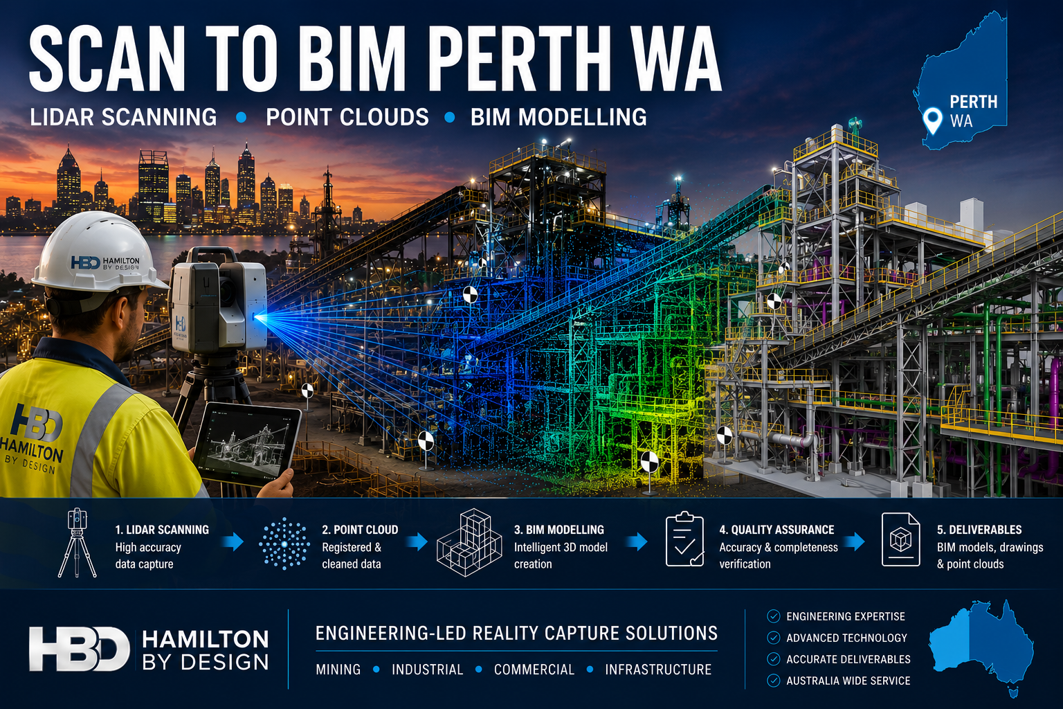
Scan to BIM Perth WA

Scan to BIM Perth WA engineering workflow showing LiDAR scanning, point cloud processing and BIM modelling of a Western Australian industrial facility using Hamilton By Design reality capture services.

Scan to BIM Perth WA

Engineering-Led Scan to BIM Services Across Perth and Western Australia

Hamilton By Design provides professional Scan to BIM services throughout Perth and Western Australia, helping mining, industrial, commercial, infrastructure and construction organisations transform accurate 3D laser scan data into intelligent Building Information Models (BIM).

Using engineering-grade LiDAR scanning technology and advanced BIM workflows, we capture existing facilities, process plants, buildings and infrastructure assets and convert them into accurate digital models suitable for design, planning, construction and asset management.

Whether your project involves a brownfield mining upgrade in the Pilbara, a commercial building in the Perth CBD, a processing plant in Kwinana or infrastructure works across regional Western Australia, our Scan to BIM services deliver reliable information for better engineering and project outcomes.


What is Scan to BIM?

Scan to BIM is the process of converting 3D laser scan data into an intelligent Building Information Model.

The process begins with high-accuracy LiDAR scanning, which captures millions of measurement points across a site. This data forms a point cloud that accurately represents existing conditions.

The point cloud is then used to create a BIM model containing structural, architectural and mechanical information that can be used throughout the project lifecycle.

The result is a highly accurate digital representation of the asset that supports:

  • Engineering design
  • Construction planning
  • Asset management
  • Facility upgrades
  • Maintenance planning
  • Clash detection
  • Digital twin development

Engineering-Led BIM Modelling

Unlike many scanning providers that focus only on data capture, Hamilton By Design combines engineering experience with reality capture technology.

This means the final BIM model is developed with an understanding of:

  • Mechanical systems
  • Structural steel
  • Conveyors
  • Chutes
  • Tanks
  • Pipework
  • Platforms and access systems
  • Process equipment
  • Material handling infrastructure

Our engineering background allows us to understand how facilities operate and how accurate models can improve future design decisions.


Perth Industries Using Scan to BIM

Mining and Resources

Western Australia remains one of the world’s largest mining regions.

Scan to BIM supports:

  • Iron ore facilities
  • Gold processing plants
  • Lithium operations
  • Rare earth projects
  • Bulk material handling systems
  • Port infrastructure

Accurate BIM models help engineering teams reduce shutdown durations and improve planning for plant upgrades.


Industrial Manufacturing

Many Perth manufacturers operate facilities that have evolved over decades.

Often existing drawings are incomplete or outdated.

Scan to BIM enables:

  • Accurate facility documentation
  • Equipment replacement projects
  • Structural upgrades
  • Capacity expansion projects
  • Maintenance planning

Commercial Buildings

Commercial property owners increasingly use BIM models to manage assets.

Applications include:

  • Building refurbishment
  • Services upgrades
  • HVAC replacement
  • Tenant fit-outs
  • Facility management

Infrastructure Projects

Scan to BIM can support:

  • Rail infrastructure
  • Ports
  • Water treatment facilities
  • Pump stations
  • Utility corridors
  • Government infrastructure

Accurate BIM models reduce project risk by ensuring designs are based on real-world conditions.


Our Scan to BIM Workflow

1. Site LiDAR Scanning

We perform engineering-grade laser scanning using professional reality capture equipment.

Millions of measurement points are collected across the facility.


2. Point Cloud Registration

Individual scans are aligned and processed into a unified point cloud.

Typical deliverables include:

  • E57
  • RCP
  • RCS
  • LAS

3. BIM Model Development

The point cloud is converted into BIM geometry using industry-standard software.

Models may include:

  • Structural steel
  • Mechanical equipment
  • Pipework
  • Buildings
  • Platforms
  • Access systems

4. Quality Assurance

Models are checked against scan data to verify accuracy and completeness.


5. Deliverables

Typical outputs include:

  • Autodesk Revit Models
  • Navisworks Models
  • IFC Files
  • DWG Drawings
  • PDF Documentation
  • Point Cloud Files

Benefits of Scan to BIM

Improved Accuracy

Laser scanning captures existing conditions with significantly greater accuracy than traditional site measurement methods.

Reduced Design Risk

Design teams can work from verified information rather than assumptions.

Faster Project Delivery

Accurate digital models reduce site revisits and minimise redesign.

Better Asset Management

Facility owners gain an accurate digital representation of their assets.

Improved Collaboration

BIM models provide a common source of information for engineers, designers, contractors and asset owners.


Scan to BIM for Brownfield Mining Projects

Brownfield projects often present unique challenges.

Existing facilities may contain undocumented modifications, ageing infrastructure and limited historical records.

Scan to BIM allows engineering teams to:

  • Verify existing conditions
  • Identify clashes before construction
  • Reduce shutdown risks
  • Improve design confidence
  • Support future digital twin initiatives

For mining operations throughout Perth, the Pilbara, Goldfields and regional Western Australia, accurate BIM models can significantly improve project outcomes.


Why Choose Hamilton By Design?

Hamilton By Design combines:

โœ” Engineering Experience

โœ” LiDAR Scanning Expertise

โœ” BIM Modelling Capability

โœ” Mechanical Design Knowledge

โœ” Structural Drafting Experience

โœ” Australia-Wide Project Delivery

โœ” Mining Industry Experience

We understand both the technology and the engineering requirements behind successful Scan to BIM projects.


Hamilton By Design logo displayed on a blue tilted rectangle with a grey gradient background

Scan to BIM Perth WA

If you require Scan to BIM services in Perth or anywhere across Western Australia, Hamilton By Design can provide engineering-grade reality capture and BIM modelling solutions tailored to your project requirements.

From mining facilities and industrial plants to commercial buildings and infrastructure projects, we help organisations capture existing conditions and create accurate digital models that support safer, more efficient project delivery.

Talk to Us – Contact Us

Name
Would you like us to arrange a phone consultation for you?
Address

Our clients:
3D LiDAR Scanning Darwin for engineering surveys, laser scanning, reality capture and point cloud modelling services
3D LiDAR Scanning Australia engineering services for laser scanning, reality capture, scan-to-CAD, Scan-to-BIM and as-built documentation across Australia
3D LiDAR scanning services on the Central Coast providing engineering-grade laser scanning, point cloud capture, scan-to-CAD modelling and industrial reality capture for infrastructure and industrial projects.
3D LiDAR Scanning Perth for engineering surveys, laser scanning, reality capture and point cloud modelling services
3D LiDAR Scanning Sydney for engineering surveys, laser scanning, reality capture and point cloud modelling services
3D LiDAR Scanning Brisbane for engineering surveys, laser scanning, reality capture and point cloud modelling services
3D LiDAR Scanning Canberra for engineering surveys, laser scanning, reality capture and point cloud modelling services
3D LiDAR Scanning Newcastle for engineering surveys, laser scanning, reality capture and point cloud modelling services
3D LiDAR Scanning Adelaide for engineering surveys, laser scanning, reality capture and point cloud modelling services

SolidWorks Point Cloud to CAD Workflow | From LiDAR Scans to Detailed Engineering Drawings

SolidWorks Workflow for Converting Point Cloud Data into Detailed Engineering Drawings

From Reality Capture to Fabrication Documentation

The rapid adoption of terrestrial LiDAR scanning and engineering-grade reality capture technologies has fundamentally changed the way engineering projects are executed. For decades, engineers, designers and BIM specialists have relied on traditional workflows that begin with conceptual layouts, survey control, architectural envelopes or predefined design models. Today, however, many industrial projects start with something entirely different: a point cloud.

Instead of beginning with assumptions about what exists, engineering teams can now begin with measured reality.

This shift has significant implications for how projects are planned, modelled and documented. It also raises an important discussion regarding the role of Building Information Modelling (BIM), top-down modelling techniques and traditional design workflows when accurate point cloud information is available from the outset.

While BIM remains a powerful methodology, reality capture introduces a different way of thinking that is particularly valuable for brownfield, industrial, mining, manufacturing and infrastructure projects.

The reality is that neither approach is universally better than the other.

As with most engineering decisions, it is often a case of horses for courses.


The Rise of Engineering-Grade Reality Capture

Modern terrestrial LiDAR scanners can capture millions of points every second, producing highly accurate three-dimensional representations of existing facilities.

These systems are now routinely used throughout:

  • Mining operations
  • Mineral processing plants
  • Smelters
  • Power stations
  • Water treatment facilities
  • Manufacturing plants
  • Commercial buildings
  • Hospitals
  • Transport infrastructure
  • Refineries

Unlike traditional survey methods that capture selected points, LiDAR scanning captures entire environments.

The resulting point cloud becomes a digital record of reality.

Engineers can then revisit the site virtually, long after the field work has been completed.

This offers significant advantages including:

  • Reduced site visits
  • Improved safety
  • Faster design development
  • Better clash detection
  • Enhanced stakeholder collaboration
  • Improved asset documentation
  • Accurate retrofit design

For industrial facilities where access may be restricted, hazardous or costly, point cloud data often becomes one of the most valuable project assets available.


Understanding Point Clouds

A point cloud is a collection of millions or billions of measured XYZ coordinates.

Each point represents a location in space.

When combined, these points create a highly detailed representation of physical objects including:

  • Structural steel
  • Pipework
  • Equipment
  • Conveyors
  • Tanks
  • Buildings
  • Mechanical components
  • Electrical services
  • Access systems

Modern scanners may also capture colour information, intensity data and imagery, creating a realistic digital twin of the physical environment.

Unlike traditional CAD models, point clouds contain measured information rather than designed information.

This distinction is important.

A CAD model represents what was intended.

A point cloud represents what actually exists.

For brownfield engineering projects this difference can be substantial.


Why Traditional BIM Workflows Can Struggle

Building Information Modelling originated primarily within the architectural and construction sectors.

The traditional BIM process generally follows a sequence such as:

Concept Design โ†’ Schematic Design โ†’ Detailed Design โ†’ Construction โ†’ Asset Management

The model evolves as the project progresses.

In many BIM workflows the process begins with an architectural envelope or predefined design geometry.

Walls, floors, columns and services are created within a structured modelling environment.

This approach works exceptionally well for:

  • New buildings
  • Greenfield developments
  • Commercial construction
  • Architectural projects
  • Civil infrastructure projects

However, industrial facilities rarely fit neatly into these categories.

A mining plant built over 40 years may contain:

  • Multiple undocumented modifications
  • Legacy equipment
  • Inaccurate drawings
  • Informal field changes
  • Missing records
  • Deformed structures
  • Equipment relocations

In these situations the design model is often less accurate than the physical asset itself.

This creates a challenge.

Traditional BIM workflows frequently assume the model is the primary source of truth.

Reality capture reverses that assumption.

The point cloud becomes the source of truth.

The model simply becomes a representation of measured reality.


Reality-First Engineering

A reality-first workflow begins with data acquisition rather than design assumptions.

The process typically follows:

  1. Site Scanning
  2. Point Cloud Registration
  3. Quality Assurance
  4. Point Cloud Optimisation
  5. Model Development
  6. Engineering Analysis
  7. Drawing Production
  8. Construction Documentation

Instead of asking:

“What should this facility look like?”

The workflow asks:

“What does this facility actually look like?”

This subtle change can significantly improve project outcomes.


SolidWorks and Point Cloud Modelling

SolidWorks has evolved into a powerful platform for working with reality capture data.

While originally developed as a mechanical design system, modern versions provide excellent capabilities for integrating scan data into engineering workflows.

Point clouds can be imported through various formats including:

  • E57
  • LAS
  • XYZ
  • PLY
  • STL
  • OBJ
  • Mesh formats

Depending on project requirements, the workflow may involve:

  • Direct point cloud reference
  • Mesh generation
  • Surface modelling
  • Parametric feature creation
  • Reverse engineering
  • Assembly development

The chosen approach depends on the intended deliverable.


The Importance of Top-Down Modelling

Top-down modelling becomes particularly valuable when working from point cloud data.

Traditional bottom-up modelling involves creating individual components separately before assembling them.

Top-down modelling reverses this process.

The assembly becomes the master model.

Individual components are then developed within the context of the larger system.

For industrial facilities this approach offers significant advantages.


Why Top-Down Modelling Works Well with Point Clouds

A point cloud already contains contextual information.

Pipework exists relative to equipment.

Equipment exists relative to structures.

Structures exist relative to buildings.

Everything already has a defined relationship.

Top-down modelling allows engineers to preserve these relationships.

For example:

A conveyor transfer chute may be modelled directly within the context of:

  • Existing conveyor structure
  • Existing walkways
  • Existing pipework
  • Existing electrical services
  • Existing maintenance access

The design develops within the reality captured environment.

This significantly reduces the risk of clashes.


Skeleton Models and Layout Control

One of the most effective top-down approaches involves the use of skeleton models.

A skeleton model contains:

  • Key reference geometry
  • Design planes
  • Centre lines
  • Control sketches
  • Interface locations

When working from point clouds, the skeleton model can be created directly from measured geometry.

This establishes a reliable framework for the remainder of the design.

Individual components then inherit relationships from the skeleton model.

Benefits include:

  • Improved consistency
  • Faster design changes
  • Better design intent control
  • Reduced assembly errors

Scan-to-CAD Workflow

A typical Scan-to-CAD workflow within SolidWorks may follow the following sequence.

Step 1 โ€“ Site Capture

Engineering-grade LiDAR scanning is completed on site.

Data is collected from multiple scanner positions.

The objective is to capture sufficient coverage while maintaining registration quality.


Step 2 โ€“ Registration

Individual scans are registered into a unified coordinate system.

This produces a complete point cloud.

Quality control is performed to verify registration accuracy.

Typical industrial projects may achieve overall accuracies within several millimetres.


Step 3 โ€“ Point Cloud Cleaning

Noise is removed.

Unwanted objects may be filtered.

Temporary equipment can be excluded.

The objective is to create a usable engineering dataset.


Step 4 โ€“ Import into Modelling Environment

The point cloud is imported into the modelling platform.

At this stage the cloud becomes a digital reference.

The cloud itself is generally not modified.

Instead, engineering geometry is created around it.


Step 5 โ€“ Create Reference Geometry

Reference planes, axes and coordinate systems are established.

These form the foundation of the modelling process.

Top-down methodologies become particularly valuable at this stage.


Step 6 โ€“ Build Parametric Models

Engineering components are modelled using parametric features.

Examples include:

  • Structural steel
  • Tanks
  • Pipework
  • Chutes
  • Platforms
  • Conveyors
  • Ductwork

The resulting model remains editable and fully configurable.


Step 7 โ€“ Validation

The model is compared against the point cloud.

Engineers verify fit, alignment and geometry.

Potential clashes are identified early.


Step 8 โ€“ Drawing Production

Detailed drawings are generated directly from the validated model.

Deliverables may include:

  • General arrangements
  • Fabrication drawings
  • Assembly drawings
  • Pipe spool drawings
  • Structural steel details
  • Installation drawings
  • Bill of materials

Reverse Engineering Using Point Clouds

Reverse engineering is one of the most powerful applications of reality capture.

Many industrial facilities contain components with:

  • Missing drawings
  • Obsolete equipment
  • Unknown suppliers
  • Legacy modifications

Point clouds provide a practical starting point.

Engineers can recreate:

  • Mechanical components
  • Structural systems
  • Pipework networks
  • Fabricated assemblies

The resulting CAD models become valuable engineering assets.


Parametric Models versus Mesh Models

A common mistake is assuming that a mesh model is equivalent to a CAD model.

It is not.

A mesh represents geometry.

A parametric model represents engineering intent.

This distinction is critical.

A parametric SolidWorks model allows:

  • Dimension changes
  • Configuration control
  • Design modifications
  • Manufacturing documentation
  • Finite element analysis

For most engineering applications, converting point clouds into intelligent parametric models provides significantly greater value than simply generating meshes.


Producing Detailed Engineering Drawings

Once a validated model exists, drawing production becomes straightforward.

SolidWorks can automatically generate:

  • Orthographic views
  • Sections
  • Detail views
  • Exploded views
  • Bills of materials
  • Weldment cut lists

This dramatically reduces drafting effort.

Because the drawings originate from the model, consistency is maintained throughout the project.


Brownfield Projects Benefit Most

The reality-first workflow delivers the greatest value in brownfield environments.

These include:

  • Operating mines
  • Smelters
  • Refineries
  • Processing plants
  • Manufacturing facilities
  • Water treatment plants

In these environments accurate existing-condition information is often more valuable than historic drawings.

A point cloud provides a measurable record of the asset as it exists today.


BIM versus Point Cloud Driven Engineering

This discussion is sometimes framed as:

“BIM versus Reality Capture.”

In practice this is the wrong question.

Reality capture and BIM should not be viewed as competing technologies.

They solve different problems.

BIM provides:

  • Information management
  • Design coordination
  • Asset lifecycle management
  • Construction planning
  • Facility management integration

Reality capture provides:

  • Existing-condition verification
  • Accurate geometry
  • Retrofit design support
  • Asset documentation
  • Digital twin creation

The most successful projects often combine both approaches.


A Modern Hybrid Workflow

Increasingly, engineering organisations are adopting a hybrid workflow.

The process becomes:

Reality Capture โ†’ Engineering Model โ†’ BIM Integration

Rather than creating BIM models based on assumptions, the BIM environment is populated using measured reality.

This approach improves confidence throughout the project lifecycle.

The BIM system benefits from more accurate geometry.

The engineering team benefits from reliable site information.

The asset owner benefits from better data quality.

Everybody wins.


The Future of Digital Engineering

The future of engineering is likely to become increasingly reality driven.

Advancements in:

  • LiDAR technology
  • Mobile scanning
  • Drone scanning
  • Artificial Intelligence
  • Automated feature extraction
  • Digital twins

will continue to accelerate the adoption of reality capture workflows.

However, traditional engineering principles remain essential.

Engineers still need to understand:

  • Design intent
  • Structural behaviour
  • Manufacturing processes
  • Construction methods
  • Asset management requirements

Technology provides information.

Engineering provides understanding.


SolidWorks provides an exceptionally capable platform for converting point cloud data into detailed engineering models and fabrication drawings. When combined with top-down modelling methodologies, point clouds become far more than visual references; they become the foundation of the engineering workflow.

Traditional BIM methodologies remain highly effective for greenfield projects and building-centric developments where the design model drives project delivery. However, in brownfield industrial environments the reality often differs from the original design documentation. In these situations, a point cloud frequently becomes the most accurate representation of the asset available.

Rather than viewing BIM and reality capture as competing philosophies, modern engineering teams should recognise the strengths of each approach. BIM excels at information management, coordination and lifecycle planning, while point cloud-driven workflows excel at capturing existing conditions and enabling accurate retrofit design.

Ultimately, the most effective solution is often a hybrid approach that combines the strengths of both. By starting with measured reality, developing intelligent parametric models in SolidWorks and integrating those models into broader BIM environments where appropriate, engineers can reduce risk, improve accuracy and deliver higher quality outcomes.

As digital engineering continues to evolve, the question is no longer whether point clouds should be used. The question is how effectively organisations can transform reality capture data into actionable engineering information that supports design, construction, operation and long-term asset management.

Hamilton By Design logo displayed on a blue tilted rectangle with a grey gradient background

Contact Us – Talk to Us

Name
Would you like us to arrange a phone consultation for you?
Address

Our Clients:
3D CAD Modelling Australia service banner for Hamilton By Design
3D LiDAR scanning and 3D modelling service button โ€” laser scanner capturing a point cloud for engineering and CAD modelling
Mechanical engineering services
3D CAD Modelling Australia service banner for Hamilton By Design
Mechanical, Structural & Pipework Drafting service banner by Hamilton By Design featuring white text on a blue background.
Australian Drafting logo featuring bold white text reading "Australian Drafting" centred on a blue rounded rectangle background.
Blue banner graphic displaying the text "Point Cloud to CAD - Australia" in large white lettering, representing point cloud processing, scan-to-CAD conversion and digital engineering services across Australia.
CHPP Engineering title graphic featuring bold white text reading "CHPP Engineering" centred on a blue rounded rectangle background.
Engineering Governance title graphic featuring bold white text reading "Engineering Governance" centred on a blue rounded rectangle background.
Mechanical engineering services
Australian Drafting logo featuring bold white text reading "Australian Drafting" centred on a blue rounded rectangle background.
3D LiDAR Scanning Hunter & Newcastle banner with white text on a blue background promoting engineering-grade laser scanning services for industrial, mining and infrastructure projects across the Hunter Valley and Newcastle region.
Mechanical Engineering Hunter & Newcastle banner promoting mechanical engineering services for mining, industrial plants, power generation, manufacturing and heavy industry throughout the Hunter Valley and Newcastle region.
Structural Drafting Hunter & Newcastle banner promoting structural drafting services for mining, industrial plants, power generation, manufacturing and infrastructure projects across the Hunter Valley and Newcastle region.
Mechanical Engineering Perth WA banner for Hamilton By Design featuring white text on a blue background.
3D Laser Scanning Perth WA banner for Hamilton By Design with white text on a blue background.
SolidWorks Perth WA banner for Hamilton By Design featuring white text on a blue background.
Fabrication and product design services
Finite Element Analysis (FEA) engineering simulation button
3D LiDAR scanning and 3D modelling service button โ€” laser scanner capturing a point cloud for engineering and CAD modelling
Blue rounded button with the text โ€œSolidWorks Designโ€ in white.
Mechanical drafting services button
Structural drafting services button

Mechanical Engineering | Structural Engineering


3D LiDAR Scanning Darwin for engineering surveys, laser scanning, reality capture and point cloud modelling services
3D LiDAR Scanning Australia engineering services for laser scanning, reality capture, scan-to-CAD, Scan-to-BIM and as-built documentation across Australia
3D LiDAR scanning services on the Central Coast providing engineering-grade laser scanning, point cloud capture, scan-to-CAD modelling and industrial reality capture for infrastructure and industrial projects.

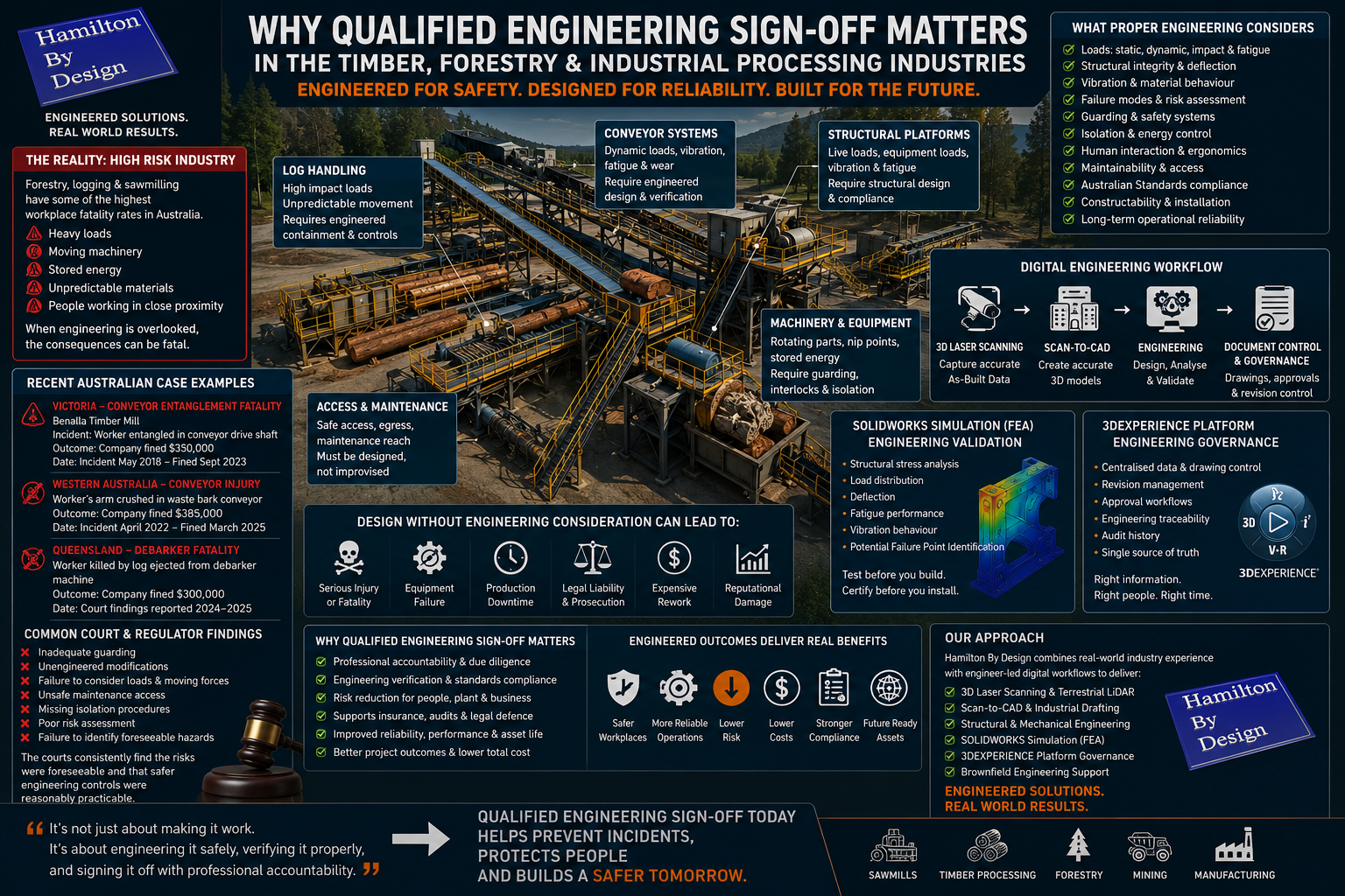
Why Qualified Engineering Sign-Off Matters in the Timber, Forestry and Industrial Processing Industries

nfographic-style industrial engineering poster by Hamilton By Design showing why qualified engineering sign-off matters in the timber, forestry and industrial processing industries. The image includes a sawmill facility with conveyors, log handling systems, engineering risk assessments, SOLIDWORKS Simulation FEA analysis and 3DEXPERIENCE engineering governance workflows.

Across Australiaโ€™s forestry, sawmill and timber processing industries, industrial infrastructure continues to evolve through ongoing maintenance, shutdown upgrades, plant expansions and operational modifications. Conveyor systems are extended, timber transfer systems are upgraded, structural steel platforms are altered, machinery is relocated and new processing equipment is integrated into ageing brownfield facilities that may have operated continuously for decades.

While many of these changes are often completed to improve productivity or maintain operational continuity, one of the greatest hidden risks within industrial environments is modifying or designing plant equipment without proper engineering review, engineering governance and qualified engineering sign-off.

In many industrial workplaces, practical trade experience is highly respected โ€” and rightly so. Skilled tradespeople are essential to fabrication, installation, shutdown works, plant maintenance and operational reliability. However, building something that functions mechanically is not the same as engineering a system that is safe, compliant, reliable and suitable for long-term industrial operation.

This distinction becomes critically important in industries such as forestry, logging and timber processing where machinery regularly handles heavy loads, rotating equipment, moving conveyors, unstable timber products, stored energy and high-throughput material handling systems.

Across sawmills and timber processing facilities throughout Australia, industrial systems are exposed to continuous operational stresses involving vibration, shock loading, impact forces, moisture, abrasive materials, dust contamination and changing environmental conditions. Conveyor systems, debarkers, screw augers, bucket elevators, log transfer systems and structural platforms must all operate safely while supporting continuous production under demanding industrial conditions.

3D CAD Modelling Australia service banner for Hamilton By Design

Without proper engineering consideration, even seemingly simple modifications can introduce serious risk.

Over the past several decades, Australian workplace regulators and courts have repeatedly prosecuted companies following incidents involving timber handling systems, conveyors, rotating shafts, sawmill machinery and plant modifications that failed to adequately consider engineering safety requirements.

In one Victorian timber mill incident, a worker died after becoming entangled in a conveyor drive shaft. WorkSafe Victoria later found that engineering controls and guarding solutions were reasonably practicable and could have prevented the fatality. In Western Australia, a timber processing company was fined after a worker suffered catastrophic arm injuries involving inadequately guarded conveyor equipment. In Queensland, a timber company faced prosecution after a worker was killed by a log ejected from a debarker machine.

Although each incident involved different operational circumstances, the underlying engineering failures followed remarkably similar patterns:
  • inadequate guarding,
  • unengineered plant modifications,
  • failure to consider loads and moving forces,
  • unsafe maintenance access,
  • missing isolation procedures,
  • poor risk assessment,
  • insufficient structural verification,
  • lack of engineering review,
  • and failure to identify foreseeable operational hazards.

These are engineering failures โ€” not simply fabrication problems.

A tradesperson may know how to weld, fabricate, cut or assemble industrial equipment, but engineering requires a much deeper understanding of how systems behave under operational conditions over time.

Proper engineering design must consider:
  • static and dynamic loading,
  • fatigue and cyclic stresses,
  • vibration,
  • structural deflection,
  • torque and rotational forces,
  • impact loading,
  • material behaviour,
  • wear characteristics,
  • human interaction with machinery,
  • guarding requirements,
  • maintainability,
  • failure modes,
  • constructability,
  • Australian Standards compliance,
  • and long-term operational reliability.

This is why qualified engineering sign-off matters.

Engineering sign-off is not simply a signature placed on a drawing. It represents professional accountability that the design has been reviewed, assessed and verified against engineering principles, foreseeable operational conditions and applicable standards.

Without proper engineering oversight, industrial businesses expose themselves to major commercial, operational and legal risk.

Poorly engineered modifications can lead to:

  • worker injury or fatalities,
  • structural failure,
  • conveyor collapse,
  • equipment damage,
  • production downtime,
  • voided insurance claims,
  • failed audits,
  • regulatory prosecution,
  • expensive shutdown rework,
  • project delays,
  • and reputational damage.

In many industrial facilities, the risk develops gradually over time. Equipment modifications are often completed during shutdowns or urgent maintenance periods where production pressure overrides long-term engineering review. Small undocumented changes accumulate over years until facilities no longer reflect their original engineered design intent.

Drawings become outdated.
Loads change.
Access paths are altered.
Equipment is relocated.
Platforms are modified.
Conveyors are extended.
Additional services are added.

Over time, facilities can drift significantly away from their original engineered condition.

This is where engineering governance becomes critically important.

At Hamilton By Design, we are an engineer-led organisation focused on delivering engineered outcomes rather than simply trade-based solutions.

While practical trade experience remains essential within industrial environments, our approach extends beyond fabrication and installation alone. We apply engineering thinking, digital engineering workflows and industrial experience to support long-term operational reliability, constructability and risk reduction.

Using engineering-grade 3D laser scanning, terrestrial LiDAR capture and scan-to-CAD workflows, we help industrial clients establish accurate as-built conditions before design or fabrication work begins.

Rather than relying on outdated PDFs or manual measurements, project teams gain access to highly accurate point cloud data that reflects real-world plant conditions. This allows engineers, fabricators and project managers to identify operational risks earlier and improve confidence before fabrication or construction begins.

Engineering-grade point clouds can then be converted into detailed CAD models suitable for:

  • structural analysis,
  • equipment integration,
  • plant upgrades,
  • fabrication detailing,
  • conveyor layouts,
  • clash detection,
  • and engineering verification.

One of the major advantages of modern digital engineering workflows is the ability to perform engineering validation before equipment is manufactured or installed onsite.

Using SOLIDWORKS Simulation and Finite Element Analysis (FEA), industrial components and structures can be digitally tested under operational loading conditions to assess how equipment may behave before fabrication occurs.

FEA allows engineers to evaluate:

  • structural stress,
  • deflection,
  • load distribution,
  • fatigue performance,
  • vibration behaviour,
  • and potential failure points.

This becomes particularly valuable within forestry and timber processing facilities where conveyor systems, transfer structures, platforms and machinery supports are exposed to continuous operational loading and vibration.

Rather than relying on assumptions or โ€œrule of thumbโ€ workshop modifications, FEA allows engineering decisions to be supported by measurable analysis and engineering verification.

This significantly improves confidence in the design process while helping reduce the risk of structural failure, overloading or premature wear.

At Hamilton By Design, digital engineering workflows can also be supported through the 3DEXPERIENCE platform, providing engineering governance and controlled management of industrial drawing systems and project information.

Modern industrial projects increasingly require:

  • revision control,
  • controlled approvals,
  • drawing issue states,
  • engineering traceability,
  • audit history,
  • and a single source of truth across multiple project stakeholders.

The 3DEXPERIENCE platform supports this by allowing controlled management of CAD models, drawings, revisions and engineering workflows within a centralised digital environment.

This provides significant advantages for industrial and brownfield projects where multiple contractors, engineers, fabricators and maintenance teams may all be interacting with the same plant infrastructure over long operational lifecycles.

Engineering governance through structured drawing control helps ensure:

  • approved drawings remain current,
  • revision history is traceable,
  • superseded drawings are controlled,
  • engineering changes are documented,
  • and project teams are working from reliable information.

In industries such as forestry, timber processing, mining and manufacturing, poor drawing control can create major operational and safety risks if outdated or unverified information is used during fabrication or construction activities.

At Hamilton By Design, our workflows focus on engineering-grade deliverables designed to support practical industrial outcomes.

This includes:

  • engineering-grade 3D laser scanning,
  • terrestrial LiDAR capture,
  • scan-to-CAD workflows,
  • industrial drafting,
  • structural and mechanical modelling,
  • FEA-supported engineering workflows,
  • revision-controlled drawing systems,
  • and brownfield engineering support.
3D LiDAR scanning and 3D modelling service button โ€” laser scanner capturing a point cloud for engineering and CAD modelling
Mechanical engineering services

We do not simply create geometry or visualisation models.

We focus on engineering workflows designed to support real-world industrial reliability, constructability and operational performance.

Because in high-risk industrial environments, โ€œit worksโ€ is not the same as โ€œit has been engineered safely.โ€

Hamilton By Design logo displayed on a blue tilted rectangle with a grey gradient background

Qualified engineering sign-off matters because the consequences of poor engineering decisions can extend far beyond production downtime โ€” affecting worker safety, operational reliability, legal liability and the long-term success of industrial infrastructure.

If your business is seeking engineered outcomes that outlast short-term fixes, Hamilton By Design provides engineer-led digital engineering support designed to help reduce risk and engineer success across industrial operations throughout Australia.

https://www.hamiltonbydesign.com.au/mechanical-engineering
3D CAD Modelling Australia service banner for Hamilton By Design
Australian Drafting logo featuring bold white text reading "Australian Drafting" centred on a blue rounded rectangle background.
Engineering Governance title graphic featuring bold white text reading "Engineering Governance" centred on a blue rounded rectangle background.
Mechanical, Structural & Pipework Drafting service banner by Hamilton By Design featuring white text on a blue background.
Mechanical engineering services
Blue rounded button with the text โ€œSolidWorks Designโ€ in white.
Finite Element Analysis (FEA) engineering simulation button
3D LiDAR Scanning Darwin for engineering surveys, laser scanning, reality capture and point cloud modelling services
3D LiDAR Scanning Australia engineering services for laser scanning, reality capture, scan-to-CAD, Scan-to-BIM and as-built documentation across Australia
3D LiDAR scanning services on the Central Coast providing engineering-grade laser scanning, point cloud capture, scan-to-CAD modelling and industrial reality capture for infrastructure and industrial projects.
3D LiDAR Scanning Perth for engineering surveys, laser scanning, reality capture and point cloud modelling services
3D LiDAR Scanning Sydney for engineering surveys, laser scanning, reality capture and point cloud modelling services
3D LiDAR Scanning Brisbane for engineering surveys, laser scanning, reality capture and point cloud modelling services
3D LiDAR Scanning Canberra for engineering surveys, laser scanning, reality capture and point cloud modelling services
3D LiDAR Scanning Newcastle for engineering surveys, laser scanning, reality capture and point cloud modelling services
3D LiDAR Scanning Adelaide for engineering surveys, laser scanning, reality capture and point cloud modelling services