Scan to BIM Services Australia | 3D Laser Scanning

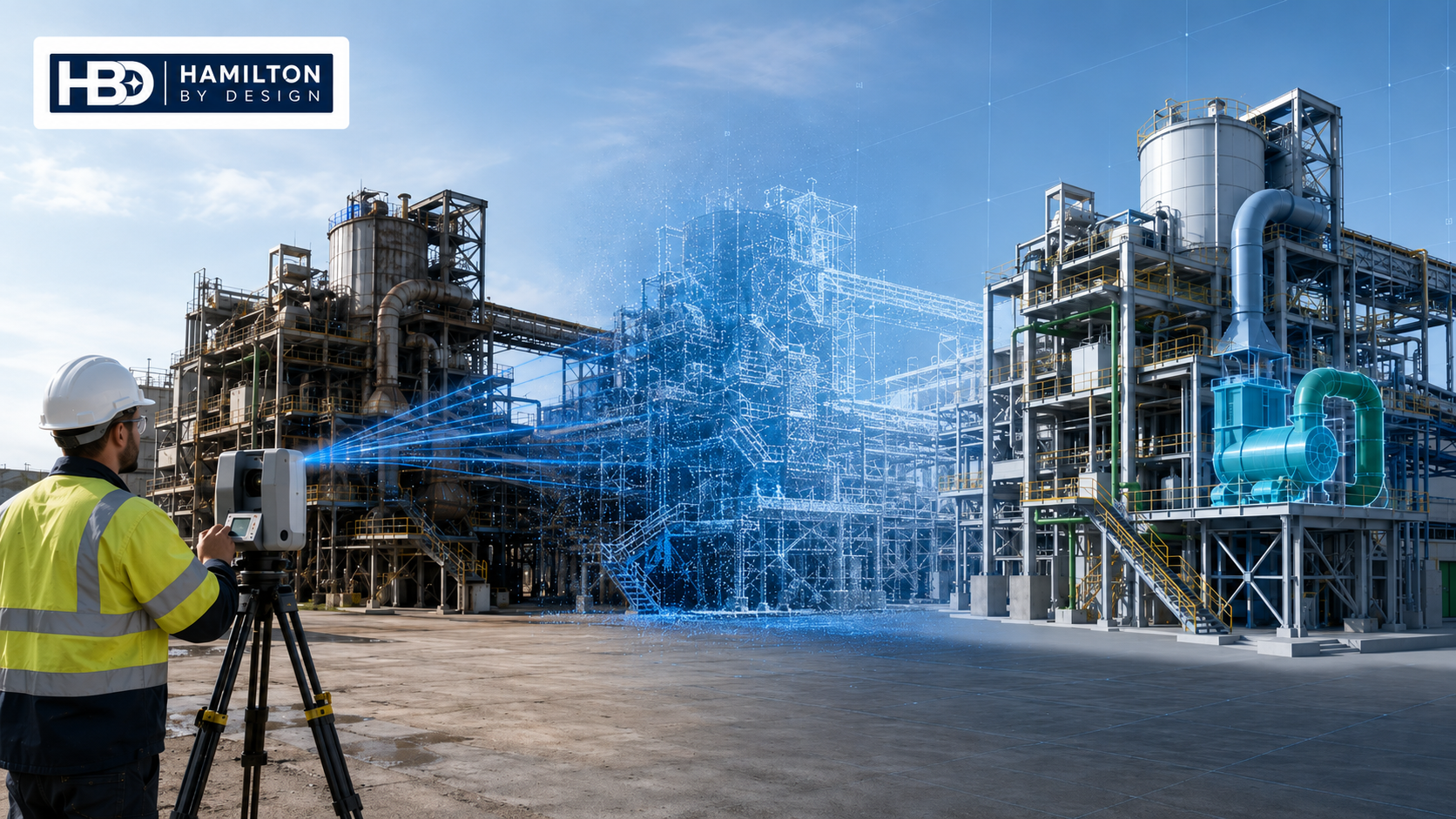
Hamilton By Design engineer using a 3D laser scanner to capture an industrial plant, transitioning from the existing facility through a point cloud into an accurate BIM model.

Scan to BIM Services for Industrial and Engineering Projects

Blue 3D LiDAR scanner icon on a tripod with scanning waves

Hamilton By Design provides engineering-led Scan to BIM services, combining accurate 3D laser scanning, point-cloud processing and BIM modelling to document existing buildings, industrial plants, infrastructure and engineering assets.

Our services help engineers, asset owners, architects, contractors, fabricators and project managers work from reliable existing-condition information rather than relying solely on outdated drawings, incomplete asset records or manual site measurements.

From the initial site survey through to the completed digital model, Hamilton By Design can provide an integrated workflow covering:

  • 3D laser scanning
  • LiDAR reality capture
  • Point-cloud registration and processing
  • Existing-condition surveys
  • Scan to CAD conversion
  • Scan to BIM modelling services
  • Mechanical and structural modelling
  • As-built verification
  • Design coordination
  • Engineering documentation
  • Asset information development

Our practical industrial and engineering experience allows us to capture and model complicated environments where access, safety, accuracy and constructability are critical.

What Are Scan to BIM Services?

Scan to BIM is the process of capturing an existing building, facility or industrial asset using terrestrial LiDAR or 3D laser scanning and converting the resulting point cloud into a structured Building Information Model.

A laser scanner records millions of measurable points across the surfaces visible from each scanning position. These individual scans are registered together to produce a coordinated three-dimensional point cloud representing the existing site.

The point cloud can then be used to develop an appropriate digital model containing architectural, structural, mechanical or building-services elements.

Depending on the requirements of the project, the completed BIM model may include:

  • Building structures and architectural elements
  • Structural steel framing
  • Platforms, stairs and access structures
  • Industrial equipment
  • Conveyors, chutes and transfer stations
  • Tanks, vessels and pump systems
  • Pipework and ductwork
  • Plant rooms and service routes
  • Electrical and mechanical equipment locations
  • Existing penetrations and connection points
  • Access restrictions and physical obstructions

The required model content, accuracy and level of detail should be established before modelling begins. This helps ensure that the final model is suitable for its intended engineering, construction, coordination or asset-management purpose.

Hamilton By Design provides Scan to BIM services across Australia for industrial, infrastructure, commercial and engineering projects requiring accurate existing-condition information.

Engineering-Led 3D Laser Scanning

Our 3D laser scanning services are delivered with an understanding of how the captured information will be used during design, fabrication, installation and maintenance.

A visually impressive point cloud is not enough. The scanning plan must capture the interfaces that matter to the project.

These interfaces may include:

  • Equipment mounting points
  • Structural connections
  • Pipe and duct routes
  • Flange locations and orientations
  • Existing steel members
  • Floor and platform levels
  • Clearances around machinery
  • Fabrication interfaces
  • Potential installation paths
  • Areas where clashes could occur

Scanning from multiple coordinated positions reduces shadows and improves coverage around complicated geometry. The resulting registered point cloud can then be reviewed before modelling begins.

This approach is particularly valuable for brownfield projects, where the existing installation may no longer match the original drawings.

Professional 3D Laser Scanning Services

Professional 3D laser scanning services provide a faster and more comprehensive method of documenting complicated facilities than relying solely on tape measures, photographs and manually recorded dimensions.

Laser scanning can support:

  • Existing-condition documentation
  • Brownfield plant upgrades
  • Equipment replacement
  • Structural modifications
  • Shutdown planning
  • Construction coordination
  • Fabrication verification
  • Clash detection
  • Reverse engineering
  • Asset-management projects
  • Refurbishment and redevelopment
  • Digital engineering workflows

The scanner captures surrounding geometry rather than only the dimensions initially identified during the site visit. This provides a more complete digital record that can be reviewed after the survey and may reduce the need for repeated site measurements.

However, appropriate planning remains important. Areas hidden behind equipment, insulation, cladding or other obstructions cannot automatically be captured. Critical interfaces should therefore be identified during the planning stage so that suitable scanner positions can be selected.

Industrial 3D Scanning Service

Hamilton By Design provides an industrial 3D scanning service for mining, manufacturing, processing, materials-handling, utilities and infrastructure environments throughout Australia.

Industrial sites present different challenges from conventional building surveys. They often contain congested equipment, restricted access, elevated structures, moving machinery, reflective surfaces and complicated interconnecting services.

Our industrial 3D scanning services can be used to capture:

  • Processing plants
  • Manufacturing facilities
  • Conveyor systems
  • Transfer stations
  • Chutes and hoppers
  • Pump stations
  • Tanks and vessels
  • Pipe racks
  • Structural steel
  • Platforms and walkways
  • Plant rooms
  • Workshops and warehouses
  • Ports and terminals
  • Water and wastewater infrastructure
  • Mining and mineral-processing facilities

The captured data can support mechanical engineering, structural modifications, replacement-equipment design, fabrication detailing, site coordination and future maintenance planning.

Because Hamilton By Design combines reality capture with engineering and drafting capability, the point cloud can be developed into practical project deliverables rather than being supplied only as raw scanning data.

Scan to BIM Modelling Services

Our Scan to BIM modelling services convert registered point-cloud information into usable digital models that reflect the existing asset.
The modelling scope can be adjusted to suit the intended project outcome.

For example, a building-services coordination project may require walls, floors, columns, ceilings, ducts, pipes and major equipment. An industrial modification project may instead require detailed modelling around structural steel, mechanical equipment and fabrication interfaces.

Not every visible object needs to be modelled. Creating unnecessary geometry increases cost, model size and processing requirements without necessarily improving the project outcome.

Before beginning the modelling process, we work with the client to establish:

  • The intended use of the model
  • The required project coordinate system
  • Areas to be included
  • Critical interfaces
  • Required model accuracy
  • Required level of information
  • Appropriate level of detail
  • File formats and software requirements
  • Naming and information-management requirements
  • Quality-assurance and verification procedures

This purpose-driven approach helps ensure that the model is detailed where accuracy matters without adding unnecessary information.

Our Scan to BIM Workflow

1. Define the Project Requirements

The first step is to understand how the scan data and BIM model will be used.

The scope should identify the survey area, critical interfaces, accuracy expectations, modelling content and final deliverables.

For industrial projects, it is also important to identify operational restrictions, site-access requirements, shutdown periods and areas containing moving equipment.

2. Plan the Site Survey

Scanner positions are planned around physical access, line of sight, safety requirements and the complexity of the facility.

Additional scan positions may be required around congested machinery, structural connections, pipework and building services.

Where project coordinates or survey control are required, these requirements should be identified before scanning begins.

3. Complete the 3D Laser Scanning

The project area is captured using terrestrial LiDAR scanning equipment.

Site photographs, reference dimensions, survey control or additional field information may also be collected where required.

Scanning can be completed across individual rooms, buildings, industrial equipment, process areas or complete facilities.

4. Register and Process the Point Cloud

Individual scans are aligned into a coordinated point-cloud dataset.

The registration is reviewed, unnecessary information can be removed, and the completed dataset is prepared for modelling or engineering use.

The registered point cloud may also be issued as a standalone project deliverable.

5. Develop the BIM Model

The required architectural, structural, mechanical or building-services elements are modelled from the point cloud.

Model development is focused on the elements and interfaces relevant to the project requirements.

The project may require a complete BIM model or a more targeted model covering only the areas affected by the proposed work.

6. Verify the Model

The completed model is checked against the registered point cloud to identify departures from the captured geometry.

Critical dimensions, connection points and fabrication interfaces can receive additional attention during this stage.

Model verification helps establish confidence that the digital information represents the captured site conditions.

7. Issue the Deliverables

Depending on the project, deliverables may include:

  • Registered point clouds
  • E57 files
  • RCP or RCS files
  • LAS files
  • BIM models
  • Revit models
  • Navisworks coordination files
  • SolidWorks or Inventor models
  • STEP, SAT or Parasolid files
  • AutoCAD drawings
  • General arrangement drawings
  • Sections and elevations
  • As-built documentation
  • Clash-detection reports
  • Equipment and asset layouts

Benefits of Scan to BIM Services

More Reliable Existing-Condition Information

Scan to BIM provides a measurable digital record of the existing asset, reducing dependence on drawings that may no longer reflect site conditions.

Reduced Design Assumptions

Engineering and design teams can review actual geometry before developing new equipment, structures or services.

This can be particularly important where new components must connect to existing steelwork, pipework, ducting or mechanical equipment.

Improved Project Coordination

A coordinated digital model allows architectural, structural, mechanical and building-services teams to review the same existing-condition information.

Proposed designs can be incorporated into the model and reviewed against the captured site conditions.

Lower Rework Risk

Potential clashes, restricted clearances and access problems can be identified before fabrication or site installation begins.

Identifying these issues during the design stage can reduce costly changes during construction or shutdown work.

Better Shutdown Planning

Project teams can remotely review congested areas and prepare installation activities before a shutdown commences.

The point cloud can support planning for demolition, lifting, access, installation sequencing and new equipment positioning.

Improved Asset Information

The completed model can contribute to future maintenance planning, facility management and asset-information systems.

It can also provide a reliable starting point for future modifications and engineering investigations.

Reduced Site Measurement Requirements

Once the site has been captured, designers and engineers can inspect and measure many features remotely from the registered point cloud.

Although additional site verification may still be required for hidden or critical features, the digital dataset can substantially reduce repeated site visits.

Scan to BIM for Brownfield Projects

Brownfield industrial facilities frequently contain equipment and structures installed across several generations of modifications.

Original drawings may not show:

  • Later plant modifications
  • Replacement machinery
  • Rerouted pipework
  • Strengthened structural members
  • Added platforms
  • Temporary alterations
  • Changed access arrangements
  • Existing damage or deformation
  • Equipment installed during previous shutdowns

Using 3D laser scanning before design provides a reliable geometric reference for planning modifications around the facility as it currently exists.

Scan to BIM can be particularly valuable where new equipment must fit between existing structures, connect to existing systems or be installed during a limited shutdown period.

Rather than developing a design around assumed dimensions, the project team can use captured site geometry to improve coordination and constructability.

Scan to BIM for Industrial Facilities

Industrial Scan to BIM projects often require a different modelling approach from conventional architectural projects.

An industrial model may need to represent:

  • Mechanical equipment
  • Structural steel
  • Process pipework
  • Conveyors and chutes
  • Tanks and vessels
  • Platforms and access systems
  • Crane rails
  • Building structures
  • Electrical equipment
  • Ductwork and extraction systems
  • Existing fabrication interfaces

The importance of individual elements will depend on the purpose of the project.

For example, a conveyor modification may require detailed geometry around the conveyor structure, transfer chute, head pulley, supporting steelwork and access platform. Objects elsewhere in the building may only require simplified representation.

Defining the intended use of the model before scanning and modelling helps direct effort towards the areas that will influence the engineering outcome.

Scan to BIM and Point Cloud to CAD

A complete BIM model is not necessary for every engineering project.

For mechanical design, reverse engineering or fabrication work, a point-cloud-to-CAD workflow may be more appropriate.

Hamilton By Design provides Point Cloud to CAD services that convert captured site information into engineering-ready models and drawings.

Point Cloud to CAD deliverables may include:

  • Solid models
  • Surface models
  • Mechanical assemblies
  • Structural models
  • General arrangement drawings
  • Fabrication drawings
  • Interface geometry
  • Two-dimensional CAD documentation
  • Equipment layouts
  • Replacement-component models

Scan to BIM is generally more appropriate where the project requires structured building information, multidisciplinary coordination, model-based construction or lifecycle information management.

Point Cloud to CAD is often more suitable where the primary outcome is mechanical design, fabrication, replacement-equipment modelling or engineering documentation.

Hamilton By Design can help establish which approach is most appropriate for the required project outcome.

Scan to BIM Applications

Our Scan to BIM modelling services can support:

Industrial Plant Upgrades

Capture existing plant, equipment and supporting structures before designing modifications or replacement systems.

Mechanical Equipment Replacement

Record equipment interfaces, mounting points, service connections and available installation clearances.

Structural Modifications

Capture existing structural steel, platforms, access systems and connection locations before new structural elements are designed.

Building Refurbishment

Document existing building geometry, services and structural elements before refurbishment or redevelopment work begins.

Shutdown Projects

Create a digital record of the work area that can be used for remote planning, design coordination and installation preparation.

Fabrication Projects

Capture critical interfaces before fabrication drawings and workshop models are developed.

Asset Documentation

Create accurate existing-condition information to support ongoing maintenance, inspections and future engineering work.

Clash Detection

Coordinate proposed structures, equipment and services against the existing-condition model before construction begins.

Why Choose Hamilton By Design?

Hamilton By Design combines practical engineering experience with advanced reality-capture and three-dimensional modelling capability.

Our services are suitable for projects that require more than a basic visual survey. We focus on producing accurate, usable information that can support engineering decisions, fabrication, construction and asset management.

Our capability includes:

  • Engineering-led site capture
  • Terrestrial LiDAR scanning
  • Industrial point-cloud processing
  • Mechanical and structural modelling
  • Scan to CAD
  • Scan to BIM
  • Reverse engineering
  • SolidWorks and Inventor modelling
  • AutoCAD and engineering drafting
  • As-built verification
  • Fabrication-focused documentation
  • Engineering design support

We support projects throughout Sydney, Newcastle, the Central Coast, Hunter Valley, Brisbane, Melbourne, Perth, Adelaide, Darwin, Mount Isa and regional Australia.

Frequently Asked Questions

What are Scan to BIM services?

Scan to BIM services involve capturing an existing building, industrial facility or infrastructure asset using 3D laser scanning and converting the resulting point cloud into a structured Building Information Model.

The model can include architectural, structural, mechanical and building-services elements according to the requirements of the project.

What is the difference between 3D laser scanning and Scan to BIM?

3D laser scanning captures the existing asset and produces a measurable point cloud.

Scan to BIM takes the point-cloud information and converts the required existing elements into a structured digital model that can support design, coordination, construction or asset management.

What is included in a 3D laser scanning service?

A typical service may include site planning, LiDAR scanning, scan registration, point-cloud processing, data verification and delivery of the registered point cloud.

BIM modelling, CAD modelling, drawings and engineering documentation can be added according to the project requirements.

Can Hamilton By Design provide scanning without BIM modelling?

Yes. Registered point-cloud data can be supplied for use by the clientโ€™s own engineering, architectural, drafting or BIM team.

Point clouds may be provided in formats such as E57, RCP, RCS or LAS, depending on the intended software and workflow.

Can you convert an existing point cloud into a BIM model?

Yes, provided the point cloud has sufficient coverage, suitable accuracy and an accessible coordinate system.

The existing data should be reviewed before the modelling scope, cost and deliverables are confirmed.

What can be included in an industrial BIM model?

Industrial BIM models may include structural steel, platforms, stairs, equipment, conveyors, chutes, tanks, pipework, ductwork, buildings and other elements required for coordination or engineering design.

The modelling scope should focus on the elements that affect the project rather than attempting to model every visible object.

How accurate is Scan to BIM?

Accuracy depends on the scanning equipment, survey control, scan registration, site conditions, line of sight and modelling requirements.

The required accuracy and intended use of the model should be agreed before scanning and modelling commence.

Can Scan to BIM support fabrication?

Yes. Scan-derived models can establish existing interfaces, available clearances, structural locations and connection points.

Fabrication models and drawings can then be developed using verified existing-condition information.

Can Scan to BIM be used for clash detection?

Yes. Proposed equipment, structures, pipework, ductwork and services can be coordinated against the existing-condition model to identify potential spatial conflicts before construction or installation.

Is Scan to BIM suitable for brownfield industrial sites?

Yes. Scan to BIM is particularly useful for brownfield facilities where original drawings may be incomplete or may not reflect later modifications.

The point cloud provides a current geometric record of the accessible and visible site conditions.

Does laser scanning capture hidden objects?

No. Laser scanners capture surfaces that are visible from the scanner positions.

Objects hidden behind equipment, walls, insulation or cladding cannot be directly captured. Additional scanner positions, access openings or supplementary measurements may be required for critical concealed features.

Can the scan data be used in SolidWorks or Autodesk Inventor?

Yes. Point-cloud information can be used to develop mechanical models and assemblies for use in SolidWorks, Autodesk Inventor and other engineering CAD systems.

The most suitable conversion process depends on the type of equipment, the required model detail and the intended engineering outcome.

How long does a Scan to BIM project take?

The timeframe depends on the size and complexity of the site, access conditions, number of scans, required model detail and final deliverables.

A small project area may require a single day of scanning, while a complete industrial facility may require several days of site capture followed by point-cloud processing and modelling.

Do you provide Scan to BIM services throughout Australia?

Yes. Hamilton By Design supports industrial, engineering, infrastructure and commercial projects throughout metropolitan, regional and remote Australia.

Discuss Your Scan to BIM Project

Accurate existing-condition information can reduce uncertainty before design, fabrication and construction begin.

Hamilton By Design provides integrated Scan to BIM services, 3D laser scanning, 3D laser scanning services, industrial 3D scanning services and Scan to BIM modelling services for projects throughout Australia.

Contact Hamilton By Design to discuss:

  • The location and size of the site
  • The areas that need to be captured
  • The intended use of the model
  • Critical equipment and interfaces
  • Accuracy requirements
  • Required file formats
  • Project timeframes
  • Site-access and induction requirements
  • The most appropriate project deliverables

By defining the required outcome before scanning begins, we can develop a practical reality-capture and modelling workflow suited to your engineering, construction or asset-management requirements.

3D Laser Scanning Services

Hamilton By Design provides engineering-grade 3D laser scanning services for industrial plants, buildings, infrastructure and brownfield project environments. Our terrestrial LiDAR scanning captures accurate existing conditions to support design coordination, as-built documentation, fabrication planning and engineering modifications.

Explore our 3D Laser Scanning Services


Industrial 3D Scanning Services

Our industrial 3D scanning services are developed for complicated operational environments, including manufacturing plants, mining facilities, conveyors, chutes, structural steel, pipework, platforms and mechanical equipment. The captured point-cloud data can support plant upgrades, shutdown planning and replacement-equipment design.

Learn More About Industrial 3D Scanning Services


Point Cloud to CAD Australia

Hamilton By Design converts registered point-cloud data into practical engineering models and drawings. Deliverables can include SolidWorks models, Inventor models, AutoCAD drawings, general arrangements, sections, elevations and fabrication-ready interface geometry.

View Our Point Cloud to CAD Services


Mechanical and Digital Engineering Services

Our engineering services connect reality capture with mechanical design, structural modelling, engineering drafting and fabrication documentation. This integrated approach helps ensure that captured site information is converted into useful project deliverables rather than remaining as an isolated point-cloud dataset.

Explore Hamilton By Design Engineering Services

Hamilton By Design logo displayed on a blue tilted rectangle with a grey gradient background

Talk to Us – Contact Us

Name
Would you like us to arrange a phone consultation for you?
Address

Our clients:


Scan to BIM Perth WA

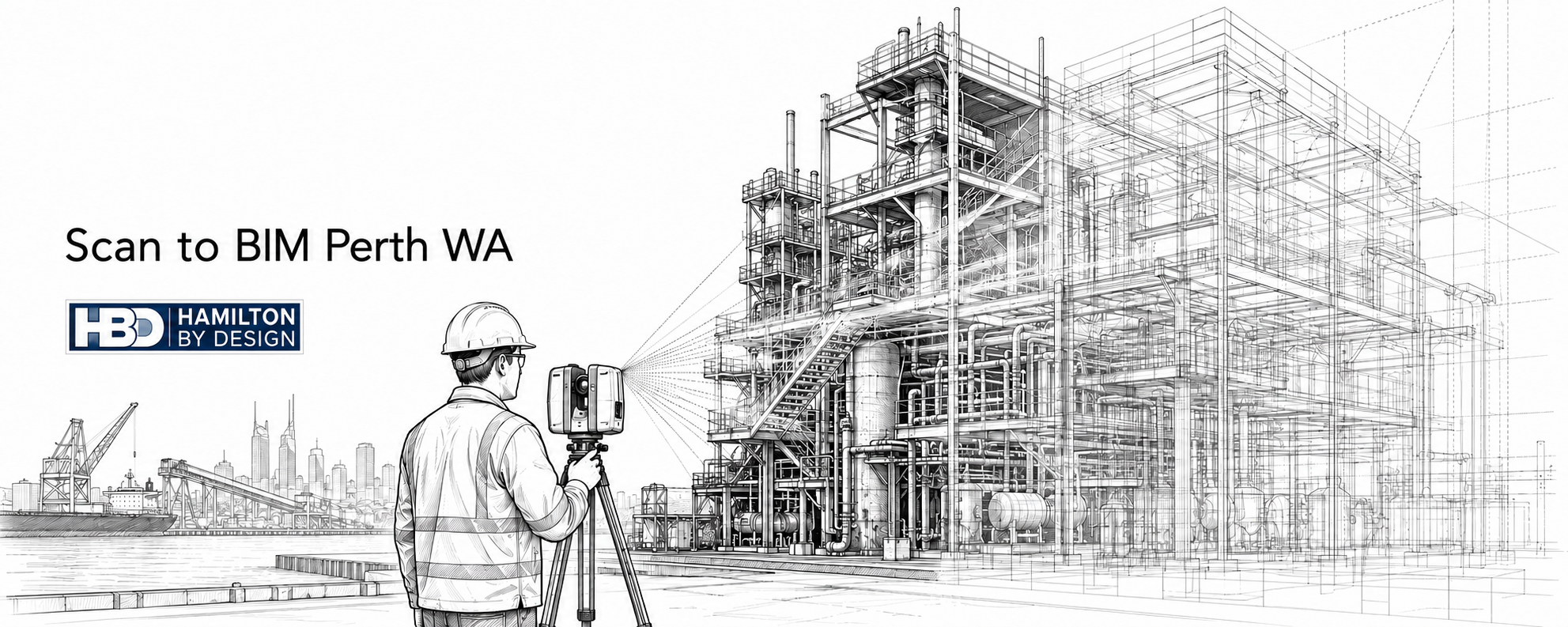
Ink line drawing of an engineer using a 3D LiDAR scanner to capture an industrial facility in Perth WA, with point cloud lines converting the site into a BIM model.

Scan to BIM Perth WA | LiDAR Scanning & BIM Modelling

Blue 3D LiDAR scanner icon on a tripod with scanning waves

Embracing the idea of Scan to BIM Perth WA would suggest accurate site information is critical for successful engineering, construction, maintenance and upgrade projects. In Perth and across Western Australia, many mining, industrial, commercial and infrastructure assets have changed over time, but the drawings have not always kept up.

Equipment gets replaced. Pipework is modified. Structural steel is strengthened or repaired. Access platforms are changed. Services are rerouted. Buildings are refurbished. Over time, the original drawings may no longer reflect what is actually installed on site.

This is where Scan to BIM Perth becomes valuable.

Scan to BIM is the process of capturing an existing site using 3D laser scanning or LiDAR technology, then converting that point cloud data into an accurate Building Information Model. The result is a usable digital model that helps engineers, project managers, builders, asset owners and maintenance teams make better decisions based on real site conditions.

Hamilton By Design provides engineering-led Scan to BIM services across Perth and Western Australia, supporting mining, industrial, commercial, infrastructure and brownfield upgrade projects.

For projects that require accurate reality capture before design or fabrication begins, Hamilton By Design also provides 3D laser scanning in Perth to capture reliable point cloud data for downstream BIM, CAD and engineering workflows.

The Biggest Problem: Inaccurate or Missing As-Built Information

The biggest problem Scan to BIM solves is the lack of reliable as-built information.

Many Perth and WA sites rely on old drawings, incomplete records or assumptions made from previous projects. In some cases, drawings may exist but do not include later site modifications. In other cases, asset owners may only have PDFs, hand-marked drawings or partial CAD files.

This creates major project risk.

If engineers are designing from inaccurate information, new equipment may not fit. Steelwork may clash with existing structure. Pipe routes may conflict with services. Fabricated parts may arrive on site and require modification. Shutdown work may take longer than planned because the real site does not match the design assumptions.

These issues can lead to:

  • Design clashes
  • Fabrication errors
  • Installation delays
  • Extra site visits
  • Shutdown overruns
  • Safety risks
  • Increased project costs
  • Poor coordination between trades
  • Rework during construction
  • Poor asset records for future maintenance

For brownfield industrial and mining projects, these risks are especially important because work is often carried out around live plant, restricted access zones, shutdown windows and complex existing infrastructure.

Scan to BIM helps reduce this uncertainty by capturing the actual site and turning it into practical digital information.

What Is Scan to BIM?

Scan to BIM combines two key processes: reality capture and Building Information Modelling.

First, the existing site is captured using 3D laser scanning or LiDAR. The scanner records millions of measurement points across the site. These points form a point cloud, which is a highly accurate 3D representation of the existing conditions.

The point cloud can then be used to create a BIM model. Depending on the project, this model may include building elements, structural steel, pipework, mechanical equipment, platforms, conveyors, access systems, services, walls, slabs, columns and other site features.

The final model may be delivered in formats such as Revit, Navisworks, IFC, DWG or other agreed digital formats.

The key value is that the model is based on measured site data, not guesswork.

Who Uses Scan to BIM in Perth?

Scan to BIM is used by a wide range of organisations and project teams across Perth and Western Australia.

Typical users include:

  • Mining companies
  • Industrial plant owners
  • Commercial property owners
  • Infrastructure operators
  • Engineering consultants
  • Mechanical engineers
  • Structural engineers
  • Architects
  • Builders
  • Fabricators
  • Shutdown planners
  • Asset managers
  • Maintenance teams
  • Project managers
  • Facility managers

For asset owners, Scan to BIM provides better records of what is installed.

For engineers, it provides a more reliable base for design.

For builders and fabricators, it helps reduce clashes and installation problems.

For maintenance teams, it supports planning, access review and future asset management.

Where Is Scan to BIM Used in Perth and WA?

Scan to BIM can be used anywhere existing conditions need to be captured accurately.

In Perth, this may include commercial buildings, hospitals, schools, industrial workshops, warehouses, manufacturing sites, processing plants, water infrastructure, ports and transport facilities.

Across Western Australia, Scan to BIM is also valuable for mining and heavy industrial locations, including processing plants, materials handling facilities, port infrastructure, power generation assets, pump stations, treatment plants and regional industrial sites.

Common WA locations and project areas include:

  • Perth CBD
  • Kwinana
  • Henderson
  • Welshpool
  • Canning Vale
  • Fremantle
  • Rockingham
  • Bunbury
  • Geraldton
  • Kalgoorlie
  • Port Hedland
  • Karratha
  • Pilbara
  • Goldfields
  • Regional Western Australia

Hamilton By Design supports broader engineering and scanning work through its Perth WA engineering and 3D scanning services page, which is a useful internal location hub for Perth-based clients.

How the Scan to BIM Process Works

A typical Scan to BIM workflow includes several stages.

1. Project Scope and Capture Planning

Before scanning begins, the project team needs to understand what the model will be used for.

This is important because not every Scan to BIM project needs the same level of detail. A model for architectural refurbishment may require different information compared with a model for conveyor upgrades, pipework modifications, structural access design or plant layout changes.

Key questions include:

  • What area needs to be captured?
  • What level of detail is required?
  • Is the model for design, construction, asset records or maintenance?
  • Are mechanical and structural elements required?
  • Are services and pipework required?
  • What deliverable format is needed?
  • Is the work being used for clash detection?
  • Is the site live, restricted or difficult to access?

Clear scope at the start helps ensure the final model is useful.

2. 3D Laser Scanning or LiDAR Site Capture

The site is captured using professional 3D scanning equipment. The scanner collects accurate spatial data from multiple positions around the site.

For complex industrial facilities, multiple scan positions may be required to capture equipment, steelwork, pipework, access platforms, conveyors and building elements from different angles.

The result is a point cloud that represents the real site geometry.

3. Point Cloud Registration

After site capture, the individual scans are registered together into a single coordinated point cloud.

This stage aligns the scans so the full site can be reviewed as one digital environment.

Typical point cloud formats may include:

  • E57
  • RCP
  • RCS
  • LAS

The registered point cloud becomes the foundation for the BIM model.

4. BIM Model Development

The point cloud is then used to create a BIM model. Depending on the project, this may include modelling architectural, structural, mechanical or services elements.

For industrial and mining projects, modelled items may include:

  • Structural steel
  • Platforms
  • Stairs
  • Handrails
  • Pipework
  • Tanks
  • Pumps
  • Conveyors
  • Chutes
  • Hoppers
  • Mechanical equipment
  • Access areas
  • Building structure
  • Services corridors

The goal is not just to make the model look good. The goal is to create a model that supports real project decisions.

Where CAD deliverables are required rather than a full BIM workflow, Hamilton By Design can also convert point cloud data into engineering models and drawings through its Scan to CAD Perth service.

5. Quality Review Against the Point Cloud

Once the BIM model is created, it should be checked against the point cloud. This helps confirm that the model reflects the captured site conditions and that the required scope has been covered.

Quality review is important because Scan to BIM is only useful if the model is accurate enough for the intended purpose.

A model used for general planning may not require the same detail as a model used for fabrication coordination, clash detection or construction sequencing. The required accuracy and level of detail should match the project outcome.

6. Delivery of BIM and CAD Outputs

Final deliverables depend on the project requirements.

Common deliverables include:

  • Revit model
  • Navisworks model
  • IFC model
  • DWG drawings
  • 2D plans
  • Sections and elevations
  • PDF documentation
  • Registered point cloud
  • E57 files
  • RCP / RCS files
  • Clash detection model
  • As-built documentation

Tools That Assist With Scan to BIM

Scan to BIM relies on a combination of capture equipment, point cloud software, BIM software and engineering review.

Useful tools include:

ToolPurpose
3D laser scanner / LiDARCaptures accurate site geometry
FARO Focus / terrestrial scannerEngineering-grade site capture
FARO SCENEPoint cloud registration and processing
Autodesk ReCapPoint cloud preparation for Autodesk workflows
RevitBIM model development
NavisworksCoordination and clash review
AutoCAD2D drawings and CAD outputs
IFCModel exchange between software platforms
E57 / RCP / RCS / LASPoint cloud delivery formats
SolidWorks / InventorMechanical modelling where required

The right tools depend on the final use of the data. A commercial building project may require a Revit-focused workflow, while an industrial plant upgrade may need a combination of point cloud, CAD, BIM and mechanical modelling outputs.

Why Engineering-Led Scan to BIM Matters

Not all Scan to BIM providers approach the work the same way.

Some providers focus mainly on scanning and visual modelling. That may be enough for some building documentation projects, but industrial and mining sites often need a deeper understanding of how the asset works.

Engineering-led Scan to BIM is different because the model is developed with practical project outcomes in mind.

For example, in a processing plant, the important question may not simply be โ€œwhat does the site look like?โ€ The real questions may be:

  • Will the new equipment fit?
  • Can the conveyor be modified safely?
  • Is there enough access for installation?
  • Will new pipework clash with existing steel?
  • Can the platform support maintenance access?
  • What needs to be removed before shutdown?
  • Can fabrication drawings be developed from the scan data?
  • What existing structure must remain untouched?

Hamilton By Designโ€™s Scan to BIM approach is suited to mechanical, structural, mining and industrial environments where the digital model needs to support real engineering decisions.

For clients working nationally, the broader Scan to BIM Mining and Industrial Facilities page provides additional context around mining, processing plant, materials handling and heavy industrial applications.

Benefits of Scan to BIM Perth

Scan to BIM provides several important benefits for Perth and WA projects.

Better Design Accuracy

Design teams can work from real site data instead of old drawings or assumptions. This reduces the risk of designing around information that no longer reflects the site.

Reduced Site Rework

Accurate existing-condition data helps reduce fabrication and installation problems. This is particularly valuable where fabricated components need to fit into existing plant, structure or services.

Improved Clash Detection

Models can be reviewed before construction to identify conflicts between new and existing elements.

This helps project teams detect problems before labour, materials and equipment are committed to site work.

Faster Project Planning

Teams can review the site digitally without always needing to return to site.

This is useful for remote WA projects where travel, access and site inductions can add time and cost.

Improved Shutdown Confidence

For mining and industrial projects, accurate scan data helps plan work before shutdown begins.

Shutdowns are often expensive and time-sensitive. Scan to BIM helps reduce uncertainty before work starts.

Better Asset Records

Owners receive a more reliable digital record of existing assets.

This can support future maintenance, inspections, upgrades and long-term asset management.

Improved Collaboration

BIM models provide a shared reference point for engineers, builders, contractors, fabricators and asset managers.

When everyone is working from the same accurate information, coordination improves.

Scan to BIM for Brownfield Projects

Brownfield projects are one of the strongest use cases for Scan to BIM.

Unlike greenfield projects, brownfield sites already contain existing plant, structure, services, access restrictions and operational constraints. The site may have been modified many times over decades.

This makes accurate information critical.

Scan to BIM helps brownfield projects by capturing the real conditions before design or fabrication begins. This reduces the chance of clashes, improves planning and gives project teams a more reliable foundation for decision-making.

For Perth and WA mining, resources, port and industrial projects, this can be the difference between a smooth installation and a costly shutdown delay.

SEO ItemSuggested Detail
Page NameScan to BIM Perth WA
URL/scan-to-bim-perth/
Keyword FocusScan to BIM Perth
LocationPerth WA
Meta DescriptionEngineering-led Scan to BIM services in Perth WA. Convert 3D laser scan data into accurate BIM models for mining, industrial, commercial, infrastructure and brownfield upgrade projects.

FAQs

What is Scan to BIM?

Scan to BIM is the process of capturing an existing site using 3D laser scanning or LiDAR, then converting the point cloud data into a Building Information Model. The model can be used for design, construction planning, asset management, clash detection and future maintenance.

Why is Scan to BIM useful for Perth and WA projects?

Scan to BIM is useful because many Perth and WA assets have incomplete or outdated drawings. By capturing the real site conditions, project teams can reduce assumptions, avoid clashes and plan upgrades with greater confidence.

What industries use Scan to BIM in Perth?

Scan to BIM is used across mining, mineral processing, ports, manufacturing, commercial buildings, infrastructure, water treatment, power generation and industrial facilities.

What deliverables can be provided from a Scan to BIM project?

Typical deliverables may include Revit models, Navisworks models, IFC files, DWG drawings, 2D plans, sections, elevations, registered point clouds, E57 files, RCP files, RCS files and PDF documentation.

Is Scan to BIM only for buildings?

No. Scan to BIM can be used for buildings, but it is also valuable for industrial plants, mining infrastructure, processing facilities, pipework, structural steel, conveyors, platforms, equipment and brownfield engineering projects.

Can Scan to BIM help reduce shutdown risk?

Yes. Scan to BIM can help project teams understand existing site conditions before shutdown work begins. This can reduce clashes, improve sequencing and reduce the risk of unexpected site issues during installation.

What is the difference between Scan to BIM and Scan to CAD?

Scan to BIM usually creates an information-rich model, often used in Revit, Navisworks or IFC workflows. Scan to CAD usually focuses on producing CAD models and drawings for engineering, drafting, fabrication or layout work. The right choice depends on the project outcome.

Do I need a full BIM model for every project?

No. Some projects only need a point cloud, 2D drawings or a Scan to CAD model. Other projects need a full BIM model for coordination, asset management or construction planning. The deliverable should match the project need.


Hamilton By Design logo displayed on a blue tilted rectangle with a grey gradient background

Scan to BIM Perth gives project teams a more reliable way to understand existing buildings, plants and infrastructure before design, fabrication or construction begins.

For Perth and Western Australia, where mining, industrial, commercial and infrastructure assets often involve complex existing conditions, accurate digital information can reduce risk, improve coordination and support better long-term asset management.

By combining 3D laser scanning, point cloud processing, BIM modelling and engineering experience, Hamilton By Design helps turn real site conditions into practical digital deliverables that support better project outcomes.

Talk to Us – Contact Us

Name
Would you like us to arrange a phone consultation for you?
Address

Our clients:

Shiploader 3D Scanning Perth

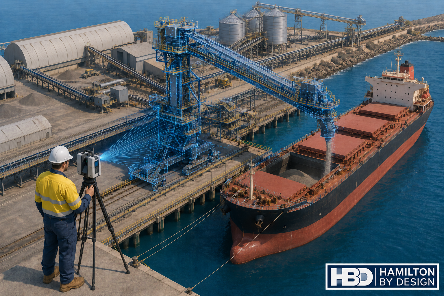
Engineer using a LiDAR scanner to capture a shiploader, conveyor system and bulk carrier at a Perth port.

Engineering-Grade LiDAR Scanning for Ports, Bulk Handling and Brownfield Shiploader Upgrades

Hamilton By Design provides shiploader 3D scanning in Perth for port operators, bulk handling facilities, engineers, fabricators and maintenance teams working with ageing shiploaders, conveyors, chutes, booms, wharf structures and access platforms.

Shiploaders are large, complex and difficult assets to modify safely. They operate in harsh marine environments, often handling abrasive bulk materials such as minerals, grain, fertiliser, alumina, coal, ore or other export products. Over time, these machines are repaired, strengthened, modified and upgraded. The problem is that the drawings do not always keep up with the real asset.

That creates risk.

When a port operator needs to replace a chute, modify a conveyor, inspect a boom, upgrade access platforms, install guarding, check clearances or plan a shutdown, the team needs accurate existing-condition data. If the project starts with old drawings or incomplete site measurements, the risk of fabrication errors, installation clashes and shutdown delays increases quickly.

Hamilton By Design uses engineering-grade LiDAR scanning to capture accurate site geometry before design, fabrication or shutdown work begins. The scan data can then be used for point cloud review, Scan-to-CAD modelling, clash checking, general arrangement drawings, fabrication support and as-built documentation.

For broader Western Australian site capture and engineering support, see our 3D Scanning Perth services.

Why Shiploader 3D Scanning Matters

A shiploader is not a simple conveyor. It is a complete mechanical, structural and operational system. A typical shiploader may include boom structures, conveyor galleries, transfer chutes, hoppers, skirts, drives, pulleys, take-up systems, dust control equipment, hydraulic systems, electrical routes, access platforms, walkways, stairs, handrails, guarding, rails, wharf interfaces and surrounding port infrastructure.

Many of these areas are difficult to measure manually. Some areas are elevated. Some are close to operating plant. Some are affected by corrosion, impact damage, product build-up, wear or previous modifications. Manual measurement may be suitable for small items, but it is often not enough when the design team needs to understand how the whole asset fits together.

3D scanning captures millions of measured points across the shiploader and surrounding infrastructure. The result is a digital point cloud that can be measured, reviewed and converted into usable engineering deliverables.

This is especially valuable for brownfield port environments where the installed condition often differs from the original drawings.

The Biggest Problem: Inaccurate As-Built Data

The biggest problem for port operators and engineers is that ageing shiploaders often do not have accurate as-built data.

Original drawings may exist, but they may no longer reflect the current condition of the machine. Over many years, shiploaders are maintained, repaired and modified. Chutes are replaced. Guards are added. Platforms are changed. Steelwork is strengthened. Conveyor components are adjusted. Services are rerouted. Dust control systems are modified. Access systems are upgraded.

Each change may make sense at the time, but unless the drawings are updated properly, the asset slowly drifts away from the documentation.

This creates problems when new work is planned.

An engineer may design a replacement chute based on old drawings, only to find that the surrounding structure has changed. A fabricator may manufacture a component that clashes with existing steelwork. A shutdown team may plan an installation sequence without knowing that access is restricted. A maintenance team may discover during the shutdown that the lifting path is blocked.

For a shiploader, these problems can become expensive quickly. Shutdown windows are limited. Port operations are time-sensitive. Fabrication rework can delay installation. A small measurement error can become a major site issue.

3D scanning helps reduce this risk by capturing the real installed condition before design and fabrication decisions are made.

Who Uses Shiploader 3D Scanning?

Shiploader 3D scanning is useful for several project groups.

Port operators use scan data to understand existing assets, plan maintenance and reduce shutdown risk.

Mechanical engineers use point clouds and CAD models to design chute modifications, conveyor interfaces, guards, brackets, transfer points and replacement components.

Structural engineers use scan data to review steelwork, access platforms, stairs, handrails, supports, boom structures and wharf interfaces.

Fabricators use accurate geometry to reduce site fit-up problems and improve confidence before manufacturing.

Maintenance planners use scan data to plan access, lifting, removal sequences and installation work before the asset is taken offline.

EPCM contractors use point cloud information for design coordination, clash checking and constructability review.

Bulk handling operators use scan data to support conveyors, transfer towers, shiploaders, wharf structures and associated plant.

What Can Be Scanned?

Hamilton By Design can scan shiploader and port infrastructure elements including:

  • Shiploader boom structures
  • Conveyor galleries
  • Transfer chutes
  • Hoppers and skirts
  • Belt feeders
  • Drive stations
  • Pulley areas
  • Take-up systems
  • Dust extraction systems
  • Spray systems
  • Access platforms
  • Walkways and stairs
  • Handrails and guarding
  • Wharf structures
  • Rail interfaces
  • Structural supports
  • Pipework and services
  • Cable trays and equipment routes
  • Maintenance access zones
  • Adjacent conveyors and transfer points

The aim is not just to create a visual record. The aim is to produce engineering information that can support real project decisions.

Where We Support Shiploader 3D Scanning

Hamilton By Design supports shiploader 3D scanning and port infrastructure projects across Perth and Western Australia, including Perth, Fremantle, Kwinana, Henderson, Cockburn Sound, Rockingham, Bunbury, Geraldton, Port Hedland, Karratha and regional WA bulk handling facilities.

The page focus is Shiploader 3D Scanning Perth, but the same workflow can support port and bulk handling infrastructure across Western Australia.

Perth is a practical engineering base for this work because many WA port, mining, processing and bulk handling projects are planned, managed and engineered from Perth, even when the assets themselves are located across regional WA.

How the 3D Scanning Process Works

1. Project Review

The first step is understanding why the scan is required.

A scan for chute replacement is different from a scan for access platform upgrades. A scan for shutdown planning is different from a scan for fabrication verification. Before scanning begins, Hamilton By Design reviews the project objective, required deliverables, areas of interest and level of detail required.

This helps make sure the scan captures the information that the engineering, maintenance or fabrication team actually needs.

2. Site Walkdown and Scan Planning

The shiploader and surrounding work areas are reviewed to identify key scan locations. The aim is to capture the asset with enough coverage and overlap to produce a reliable point cloud.

Important areas may include transfer points, boom sections, conveyor routes, access platforms, drive areas, structural supports, wharf interfaces and installation paths.

Safety and access requirements are also considered, especially around live plant, elevated work areas, marine environments and shutdown conditions.

3. LiDAR Site Capture

Hamilton By Design uses terrestrial LiDAR scanning to capture the asset. The scanner records millions of measured points, creating a detailed point cloud of the shiploader and surrounding infrastructure.

This method is faster and more complete than relying on manual measurements for large and complex brownfield assets.

4. Point Cloud Registration

After scanning, the scan data is registered into a coordinated point cloud. This creates a single usable dataset that can be opened, reviewed, measured and used for downstream modelling.

Typical point cloud deliverables may include E57, RCP, RCS or LAS files.

These files can support engineering review, CAD modelling, coordination and documentation.

5. Engineering Review

Once the point cloud is prepared, engineers and designers can review the captured asset. They can check clearances, confirm interfaces, measure existing geometry and identify areas that may affect design, fabrication or installation.

This is where engineering-led scanning becomes valuable. Hamilton By Design understands how scan data is used for design, fabrication, maintenance and brownfield modification work.

6. Scan-to-CAD Modelling

Where required, the point cloud can be converted into CAD models or drawings. This may include mechanical components, structural steel, platforms, chutes, guards, conveyor interfaces or general arrangement layouts.

For more detailed point cloud conversion support, see our Scan to CAD Perth services.

7. Drawings and Deliverables

Depending on the project, Hamilton By Design can provide registered point clouds, 2D plans, sections, elevations, general arrangement drawings, 3D CAD models, STEP files, SAT files, Parasolid files, DWG drawings, fabrication drawings, as-built documentation and clash review models.

The deliverables are selected based on the project need. Some clients only require point cloud data. Others require a full scan-to-CAD workflow with engineering drawings and fabrication support.

Tools That Assist Shiploader 3D Scanning

Hamilton By Design uses practical digital engineering tools suitable for industrial, port and bulk handling environments.

These may include FARO Focus terrestrial LiDAR scanning, FARO SCENE point cloud registration, Autodesk ReCap for RCP and RCS workflows, AutoCAD for plans and sections, SolidWorks for mechanical modelling, Autodesk Inventor for mechanical assemblies and Navisworks for coordination and clash checking.

Deliverable formats may include E57, RCP, RCS, LAS, DWG, STEP, SAT and Parasolid.

The purpose of these tools is to move the project from site capture to usable engineering information.

Services Hamilton By Design Can Provide

Hamilton By Design can support shiploader and port infrastructure projects with engineering-grade 3D laser scanning, point cloud registration, Scan-to-CAD modelling, mechanical engineering support, structural drafting, as-built documentation, fabrication drawings and shutdown planning support.

Our work can assist with chute modifications, conveyor interfaces, guarding, brackets, access platforms, walkways, stairs, handrails, support frames, replacement components and surrounding infrastructure.

For broader design and engineering capability in Western Australia, see our Perth engineering services page.

Common Shiploader Project Problems We Help Solve

Hamilton By Design can assist when existing drawings are missing, outdated or unreliable.

We can also assist when a chute needs to be replaced, a conveyor interface needs to be checked, a boom structure needs to be documented, access platforms need modification, new guarding is being installed, fabricated parts need accurate site geometry or shutdown work needs better planning.

Shiploader projects often fail because the project team discovers the real site condition too late. A point cloud gives engineers, fabricators and maintenance teams a better understanding before work moves too far into design or fabrication.

Example Use Case: Chute and Conveyor Upgrade

A common shiploader problem is a transfer chute or conveyor interface that needs modification.

The original drawing may show the design intent, but the installed condition may have changed. There may be additional steelwork, modified guards, worn liners, dust control equipment, services or access restrictions.

By scanning the area first, Hamilton By Design can capture the surrounding geometry and provide accurate information for the design team.

This helps engineers confirm available space, model replacement components, check access, reduce clashes and improve fabrication accuracy.

The result is a better chance that the new work will fit during the planned shutdown.

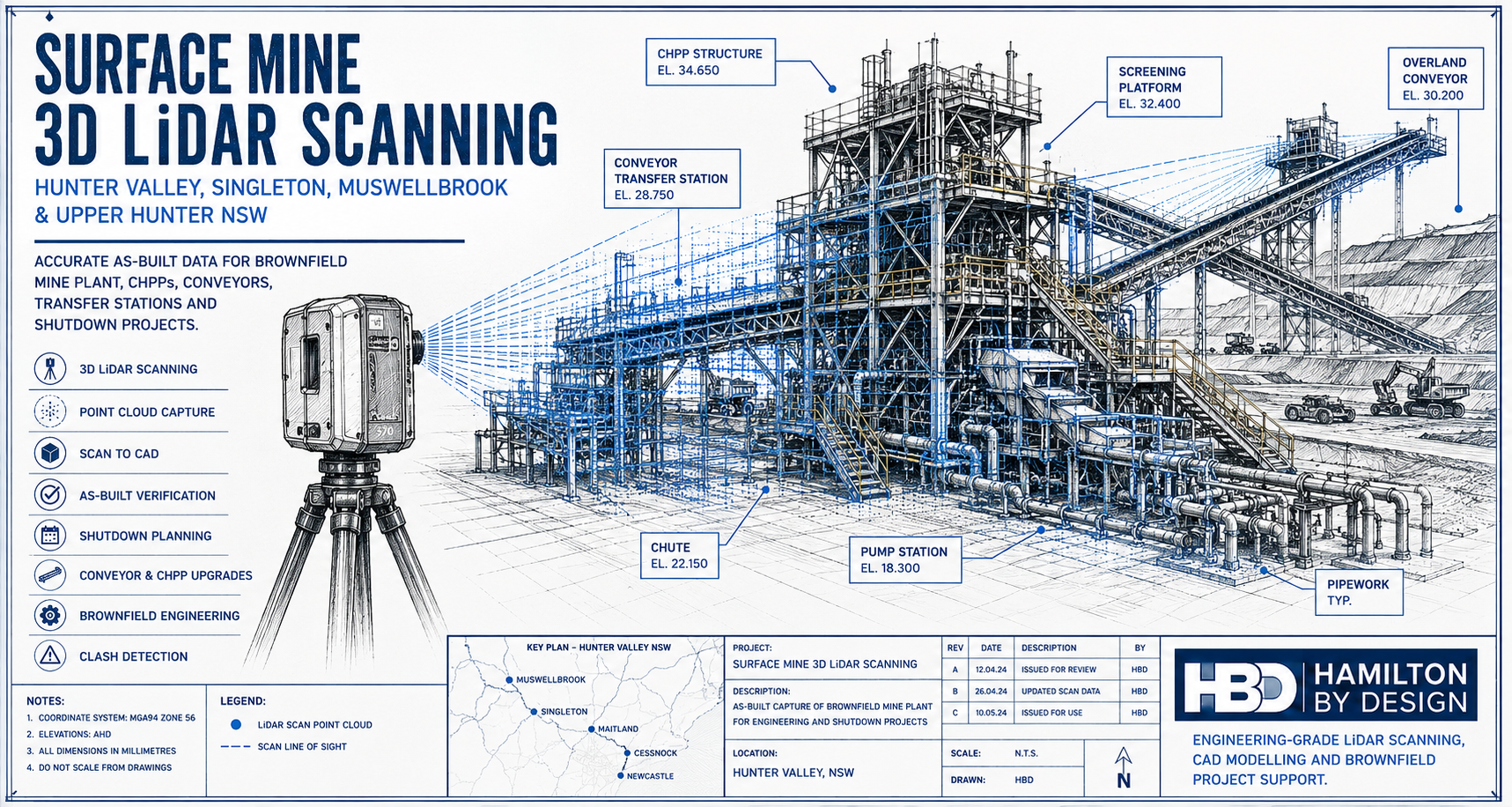
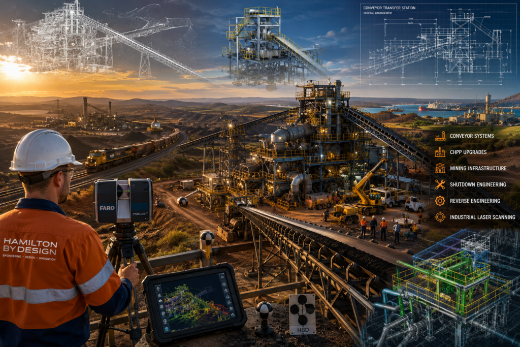
Engineering-grade 3D laser scanning and mining infrastructure project in Central Queensland, showing a conveyor transfer station, CHPP facility, coal train, industrial laser scanner, point cloud modelling and reverse engineering workflows supporting shutdown engineering and mining operations.

Example Use Case: Access Platform Modification

Shiploaders often require access improvements for inspection, maintenance and safety. This may involve stairs, platforms, handrails, ladders, guards or local structural modifications.

A scan can capture the existing structure and surrounding obstructions so that new access systems can be designed around real site conditions.

This is particularly useful when the asset has been modified over many years and the original access drawings are no longer reliable.

Example Use Case: Shutdown Planning

Shutdown time is expensive. Every hour matters.

By scanning the shiploader before the shutdown, project teams can inspect the asset digitally, measure key areas, plan removal paths, check lifting constraints, model replacement components and identify potential clashes before work begins.

This does not remove every risk, but it gives the project team better information before the asset is taken offline.

Why Engineering-Led Scanning Is Different

Not all 3D scanning is the same.

For a shiploader project, the value is not just in capturing a point cloud. The value is in understanding what the point cloud is needed for.

A survey-only approach may capture the site, but an engineering-led approach considers how the information will be used for design, fabrication, installation and maintenance.

Hamilton By Design combines LiDAR scanning with mechanical engineering, drafting and fabrication-aware modelling. That means the scan is planned around the downstream engineering outcome, not just the visual capture.

This is important for port assets because the cost of getting it wrong can be high. A small clash, incorrect bracket location, missed access constraint or outdated drawing can create real shutdown delays.

For broader mechanical design support, see our Mechanical Engineering Perth page.

FAQs

What is shiploader 3D scanning?

Shiploader 3D scanning is the process of using LiDAR scanning equipment to capture accurate three-dimensional data of a shiploader and its surrounding infrastructure. The scan creates a point cloud that can be measured, reviewed and converted into CAD models or drawings.

Why scan a shiploader before an upgrade?

A shiploader should be scanned before an upgrade because existing drawings are often outdated or incomplete. Scanning captures the real installed condition, helping engineers reduce assumptions before design, fabrication and shutdown work begins.

What parts of a shiploader can be scanned?

Hamilton By Design can scan boom structures, conveyors, transfer chutes, hoppers, guards, access platforms, stairs, handrails, wharf interfaces, drives, pulleys, services, dust control systems and surrounding port infrastructure.

Can scan data be converted into CAD drawings?

Yes. Point cloud data can be converted into 2D drawings, 3D CAD models, general arrangement drawings, sections, elevations and fabrication drawings, depending on the project requirements.

What file formats can be supplied?

Typical deliverables may include E57, RCP, RCS, LAS, DWG, STEP, SAT and Parasolid formats. The final format depends on the clientโ€™s software and required workflow.

Is shiploader scanning useful for shutdown planning?

Yes. Scanning before a shutdown helps teams check clearances, plan installation paths, identify clashes, review access and reduce the risk of discovering problems after the asset is offline.

Can 3D scanning help with chute replacement?

Yes. Chute replacement is one of the best uses for 3D scanning. The scan captures the surrounding structure, conveyor interfaces, access restrictions and existing geometry so the replacement chute can be designed with better information.

Does Hamilton By Design only work in Perth?

No. Hamilton By Design supports projects across Perth and Western Australia, including Fremantle, Kwinana, Henderson, Bunbury, Geraldton, Port Hedland, Karratha and regional bulk handling sites.

Hamilton By Design logo displayed on a blue tilted rectangle with a grey gradient background

Shiploader 3D Scanning Perth

If you are planning a shiploader upgrade, chute replacement, conveyor modification, access platform change, shutdown project or port infrastructure review, accurate as-built information is the best place to start.

Hamilton By Design provides shiploader 3D scanning Perth services for port operators, engineers, fabricators and maintenance teams working across Perth and Western Australia.

By combining engineering-grade LiDAR scanning, point cloud registration, Scan-to-CAD modelling, mechanical engineering and drafting support, Hamilton By Design helps project teams reduce assumptions, improve fabrication accuracy and plan brownfield work with greater confidence.

Contact Hamilton By Design to discuss your shiploader, conveyor, chute, wharf or port infrastructure scanning requirements.

Talk to Us – Contact Us

Name
Would you like us to arrange a phone consultation for you?
Address

Our clients:


Scan to CAD Perth

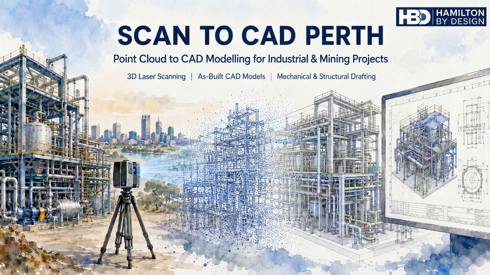
Scan to CAD Perth watercolour hero image showing a 3D laser scanner capturing an industrial plant, converting point cloud data into CAD models and engineering drawings.

Point Cloud to CAD Modelling for Industrial, Mining and Engineering Projects

Blue 3D LiDAR scanner icon on a tripod with scanning waves

Hamilton By Design provides Scan to CAD Perth services for businesses that need accurate CAD models, drawings and engineering information from existing plant, equipment, structures and sites.

Many Perth and Western Australian businesses work with assets that have been modified over many years. Drawings may be missing, outdated, incomplete or no longer trusted. This creates problems when planning upgrades, replacing equipment, modifying pipework, designing new access platforms or reverse engineering obsolete parts.

Scan to CAD helps solve this problem by converting real-world site conditions into usable CAD data.

Using 3D laser scanning and LiDAR capture, Hamilton By Design can scan existing assets and convert the point cloud into practical engineering deliverables such as 3D CAD models, 2D drawings, as-built layouts, mechanical models, structural layouts, pipework models and fabrication-ready documentation.

For related Perth services, Hamilton By Design also provides 3D laser scanning in Perth, mechanical engineering services in Perth and SolidWorks CAD support in Perth.

Our Scan to CAD Perth services support mining, industrial, manufacturing, marine, infrastructure, water, energy and process plant projects across Perth and Western Australia.


What Is Scan to CAD?

Scan to CAD is the process of capturing an existing object, machine, structure, plant room, building or industrial site using a 3D laser scanner, then converting the scan data into CAD models or drawings.

The scanner captures millions of measurement points from the real-world environment. This creates a point cloud, which can then be processed, registered and used as a reference for CAD modelling.

The CAD output may be simple or detailed depending on the project.

For example, a business may need a basic 3D layout to check whether new equipment will fit. Another project may require detailed CAD models of pipework, steelwork, access platforms, pump components or mechanical assemblies. In some cases, the final deliverable may be a set of fabrication drawings, general arrangement drawings, sections, elevations or 3D model files for engineering design.

Scan to CAD is especially useful for brownfield projects, where new design work needs to fit around existing assets.


Why Perth Businesses Use Scan to CAD Services

Perth businesses use Scan to CAD services when they need reliable information about existing assets.

This is common in mining, ports, processing plants, fabrication workshops, pump stations, utilities, marine facilities and industrial sites. Many of these sites have been changed over many years. Equipment has been replaced, pipework has been rerouted, structures have been modified and old drawings may not reflect the current condition.

When drawings cannot be trusted, engineering work becomes risky.

A new piece of equipment may clash with existing steelwork. A replacement pipe spool may not fit. A platform may be designed around incorrect dimensions. A shutdown job may be delayed because the site information was wrong. These problems can cost far more than the original drafting or scanning work.

Scan to CAD helps reduce this risk by giving engineers, project managers, fabricators and maintenance teams a clearer understanding of the existing site before design, fabrication or installation begins.

For larger Perth and WA projects, this service can also connect with Hamilton By Designโ€™s broader Perth WA engineering and 3D scanning services.


Common Problems Scan to CAD Helps Solve

One of the biggest problems businesses face is the lack of reliable drawings. In many industrial environments, original drawings are either unavailable or no longer accurate. This is particularly common where plant has been upgraded over many years without the as-built documentation being updated.

Another common problem is that OEM drawings are not available. Equipment suppliers may not provide drawings, or replacement parts may have long lead times and high costs. In these situations, Scan to CAD can assist with reverse engineering by capturing the existing part or assembly and creating CAD models for review, repair, modification or replacement.

Brownfield upgrades are another major reason for using Scan to CAD. Existing structures, conveyors, chutes, tanks, pumps, platforms, walkways and pipework can make new design work difficult. A scan provides a practical way to model the existing environment and check the proposed design before fabrication.

Shutdown work is also a key driver. During a shutdown, there is limited time to complete installation work. If a fabricated part does not fit, the cost can be significant. Scan to CAD helps reduce the chance of site rework, emergency fabrication and installation delays.


Scan to CAD for Mining and Industrial Sites in Perth

Perth is closely connected to Western Australiaโ€™s mining, resources, marine, energy and industrial sectors. Many projects are designed, managed or supported from Perth, even when the site itself is located elsewhere in WA.

Hamilton By Design supports Scan to CAD services for mining and industrial applications including:

Conveyors, chutes and transfer points.

Pump stations and pipework.

Processing plants and fixed plant equipment.

Access platforms, stairs, ladders and walkways.

Structural steel layouts.

Mechanical equipment and machine components.

Plant rooms and service areas.

Marine and ship repair projects.

Brownfield upgrade areas.

Reverse engineering of obsolete or unavailable parts.

The purpose is not only to create a point cloud. The purpose is to turn that scan data into useful engineering information.

For projects involving steelwork, platforms, pipework or industrial layouts, Hamilton By Design also provides mechanical, structural and pipework drafting in Perth WA.


From Point Cloud to Practical CAD Deliverables

A point cloud is valuable, but many businesses need more than raw scan data. They need usable CAD information that can support decisions, design work, procurement, fabrication and installation.

Hamilton By Design can convert point cloud data into a range of CAD deliverables, including:

3D CAD models.

2D CAD drawings.

General arrangement drawings.

Sections and elevations.

As-built layouts.

Pipework models.

Structural models.

Mechanical models.

STEP, SAT or Parasolid files.

SolidWorks models.

Inventor models.

AutoCAD drawings.

DWG and DXF files.

Fabrication drawings where required.

The final deliverable depends on the project requirement. A clash detection model may not need the same level of detail as a fabrication drawing. A concept model may not need every bolt and weld. A reverse engineering job may need a much higher level of detail.

This is why it is important to define the scope before scanning and modelling begins.


The Importance of Engineering Understanding

Scan to CAD is not just a software process. It requires engineering judgement.

A scanner records what it can see, but the CAD model needs to be interpreted and built by someone who understands the purpose of the work. This is especially important for mechanical, structural and industrial projects.

For example, pipework may need to be modelled using correct pipe outside diameters and centre lines. Steelwork may need to reflect real member sizes. Platforms and access systems may need to consider Australian Standards such as AS 1657. Mechanical components may need to be modelled with design intent, clearances, tolerances and manufacturing method in mind.

A visually impressive model is not always an engineering-ready model.

Hamilton By Design focuses on practical CAD outputs that can be used by engineers, fabricators, project managers and maintenance teams.


Problems Businesses Can Have With Poor Scan to CAD Services

Not all Scan to CAD services are the same.

A common problem is that businesses receive a large point cloud but do not know how to use it. The file may be too large, the format may not suit their software, or the areas they need may not have been captured properly.

Another problem is unclear scope. If the instruction is only โ€œscan the site and provide CADโ€, the result may not match what the business expected. The scope should define what needs to be scanned, what needs to be modelled, the required level of detail, the accuracy expectations, the required file formats and whether drawings are included.

Businesses can also run into trouble when the model is either under-modelled or over-modelled. Under-modelling can miss important details. Over-modelling can waste time and increase cost without adding value.

There can also be line-of-sight issues. Laser scanners cannot see through objects, insulation, guards, cladding or equipment. Hidden areas may require extra scan positions, physical measurement or site verification.

The best results come from planning the scan around the final CAD deliverable.


When Should Scan to CAD Be Used?

Scan to CAD should be considered early in a project, especially when existing information is unreliable.

It is useful before:

Plant upgrades.

Equipment installation.

Shutdown planning.

Pipework replacement.

Structural modification.

Access platform design.

Reverse engineering.

Fabrication.

Clash detection.

Layout planning.

As-built documentation.

The earlier the scan is completed, the more useful it becomes. If the scan is done after design work is already finished, it may only reveal problems late in the project. When scanning is completed early, the design team can work around the real site conditions from the start.


Scan to CAD Perth for Brownfield Engineering

Brownfield engineering is one of the strongest applications for Scan to CAD.

In a brownfield site, the challenge is not simply designing something new. The challenge is making sure the new design fits the existing plant.

This is where Scan to CAD provides value.

By converting existing site conditions into CAD, Hamilton By Design can help identify space restrictions, clashes, tie-in points, access limitations and installation constraints before work reaches site.

This can support better planning, better design decisions and reduced installation risk.

For businesses needing building, facility or infrastructure modelling from scan data, Hamilton By Design also provides Scan to BIM services in Perth WA.


Why Work With Hamilton By Design?

Hamilton By Design combines 3D laser scanning, CAD modelling, mechanical engineering, structural drafting and reverse engineering experience.

This means the Scan to CAD process is approached with the final engineering outcome in mind.

We understand that businesses do not simply need a scan. They need answers.

Will the new equipment fit?

Can the part be reverse engineered?

Can the pipework be modelled accurately?

Can the existing structure be documented?

Can the shutdown risk be reduced?

Can the CAD model be used for design, drafting or fabrication?

Our goal is to provide practical CAD information that helps businesses make better engineering decisions.


Scan to CAD Perth Services

Hamilton By Design provides Scan to CAD Perth services for businesses needing accurate, useful and engineering-focused CAD deliverables from existing assets.

Whether the project involves mining equipment, industrial plant, pipework, structural steel, mechanical components, marine repairs or brownfield upgrades, Scan to CAD can help turn site reality into usable engineering data.

If your business has missing drawings, unreliable site information, obsolete parts, shutdown risk or brownfield design challenges, Scan to CAD may be the right starting point.

Hamilton By Design can assist with 3D laser scanning, point cloud processing, CAD modelling, as-built documentation and engineering drafting for Perth and Western Australian projects.

Hamilton By Design logo displayed on a blue tilted rectangle with a grey gradient background

Need Scan to CAD Support in Perth?

Hamilton By Design provides Scan to CAD services for Perth businesses that need accurate CAD models and drawings from existing plant, equipment and structures.

We can assist with site scanning, point cloud processing, CAD modelling, as-built drawings, reverse engineering and engineering documentation for industrial and mechanical projects.

Talk to Us – Contact Us

Name
Would you like us to arrange a phone consultation for you?
Address

Our clients:

Open Cut Mine Machinery Reverse Engineering Muswellbrook NSW

Open cut mine machinery reverse engineering image showing a worn mining component being laser scanned beside a CAD model, with Hamilton By Design branding and Muswellbrook NSW text.

Replacement Parts Without OEM Drawings, Long Lead Times or Excessive OEM Costs

Open cut mining operations around Muswellbrook NSW rely on heavy machinery, fixed plant, conveyors, crushers, feeders, pumps, screens, chutes, hoppers, guards, frames and access systems to keep production moving.

When a critical machinery component wears out, cracks, fails or becomes obsolete, the first option is often to contact the original equipment manufacturer.

But for many mining maintenance teams, that creates a serious problem.

The OEM may not provide detailed drawings.
The replacement part may be expensive.
The delivery lead time may be too long.
The machine may be older, modified or no longer fully supported.

This can leave mine operators, maintenance teams and shutdown planners with limited options when they need a replacement part quickly.

Hamilton By Design supports open cut mining operations, maintenance teams, fabricators and repair workshops with engineering-grade 3D laser scanning and mining plant upgrade support, reverse engineering, CAD modelling and engineering documentation for mine machinery components.

Our focus is not open cut pit scanning or mine survey work. Our focus is machinery, fixed plant, replacement parts and brownfield equipment support.

If a component can be removed, measured, scanned or inspected, it may be possible to develop a 3D CAD model, manufacturing drawing or replacement part design that supports local manufacture, repair or redesign.


The Real Problem: OEM Drawings Are Not Available

For many mining assets, the biggest problem is not always that old site drawings are outdated. The larger problem is that the equipment owner often does not have access to the detailed OEM drawings required to reproduce or repair the part.

The mine may own the machine.

The maintenance team may own the worn component.

The workshop may be able to manufacture a replacement.

But without the correct drawings, dimensions, tolerances, materials and fit-up information, the replacement process becomes difficult.

This is a common problem with:

  • Older mining machinery
  • Imported equipment
  • Obsolete parts
  • Proprietary OEM components
  • Modified equipment
  • Worn mechanical assemblies
  • Shutdown-critical replacement parts
  • Components with long supply lead times
  • Parts that are too expensive through the OEM supply chain

When a part is urgently needed, waiting weeks or months for an imported OEM replacement may not be practical. In some cases, the part cost may also be difficult to justify, especially when a local fabrication or machining solution may be possible.

Reverse engineering provides another pathway.


What Is Mine Machinery Reverse Engineering?

Mine machinery reverse engineering is the process of capturing the geometry, features and function of an existing component so that a usable CAD model, drawing or replacement design can be created.

This may involve laser scanning, manual measurement, inspection, CAD modelling and engineering review.

The aim is to understand the part well enough to support repair, manufacture, fit-up or redesign.

Depending on the component, this may include:

  • Measuring critical diameters
  • Capturing bolt hole patterns
  • Checking shaft, bush and bearing fits
  • Modelling flanges, brackets and housings
  • Recording wear surfaces
  • Capturing complex cast shapes
  • Creating 3D CAD models
  • Producing 2D manufacturing drawings
  • Identifying practical fabrication methods
  • Supporting local machining, fabrication or casting

Reverse engineering is especially useful where the original drawings are not available from the OEM, or where the part has been modified during its service life.

Hamilton By Design also provides replacement part reverse engineering where OEM drawings are unavailable, helping asset owners move from a physical component to usable manufacturing information.


Why This Matters for Muswellbrook Mining Operations

Muswellbrook and the surrounding Upper Hunter region support major mining, industrial maintenance and heavy equipment operations. Open cut mine machinery is exposed to harsh operating conditions, heavy loads, vibration, dust, impact, abrasion and constant production pressure.

When machinery components fail, the issue is rarely simple.

A replacement part may be required urgently.

The part may need to fit into an existing machine.

The equipment may be old or modified.

The OEM may have a long delivery time.

The replacement price may be high.

The mine may need a local repair or manufacturing option.

This is where laser scanning and reverse engineering can assist. Instead of relying only on unavailable OEM drawings, the existing component can be captured, measured and converted into usable engineering information.

That information can then support local manufacturing, repair, redesign or future asset documentation.

For mining operators, contractors and industrial clients across the region, Hamilton By Design provides Hunter Valley mining engineering and 3D laser scanning services focused on practical brownfield plant, machinery and materials handling problems.


Common Machinery Parts That May Be Reverse Engineered

Hamilton By Design can assist with reverse engineering and CAD documentation for a range of mine machinery and fixed plant components.

Examples include:

  • Pump components
  • Bearing housings
  • Drive components
  • Couplings
  • Guards and covers
  • Conveyor components
  • Chute components
  • Hopper parts
  • Wear liners
  • Brackets and mounts
  • Structural frames
  • Shafts and sleeves
  • Flanges and adaptors
  • Fabricated assemblies
  • Cast components
  • Obsolete machine parts
  • Modified equipment parts

Some parts require high-detail measurement. Others require practical engineering judgement to determine which features are critical and which features can be simplified for manufacture.

The goal is not always to create a perfect visual copy of the original part. The goal is to create useful engineering information that allows the replacement part to be manufactured, fitted and used safely.


How Laser Scanning Helps

Laser scanning is useful when a component has complex geometry, difficult-to-measure surfaces or no existing CAD model.

A laser scanner captures the visible surfaces of the part as a point cloud. This data can then be used as a reference for CAD modelling and dimensional checking.

Laser scanning can be especially useful for:

  • Castings
  • Worn parts
  • Complex housings
  • Curved surfaces
  • Irregular shapes
  • Large fabricated items
  • Assemblies with multiple interfaces
  • Parts where manual measurement alone is slow or difficult

However, laser scanning is only one part of the process.

For machinery reverse engineering, critical dimensions still need to be understood. Bearing fits, shaft fits, bolt holes, machined faces, threads, splines, sealing surfaces and alignment features may require additional measurement and engineering review.

That is why Hamilton By Design combines laser scanning with practical mechanical design and CAD modelling experience.


The Reverse Engineering Workflow

A typical reverse engineering workflow may include the following steps.

1. Identify the Part and the Problem

The first step is to understand what the part does and why it needs to be replaced.

Questions may include:

  • Is the part worn, cracked, broken or obsolete?
  • Is the part required for a shutdown?
  • Is the OEM replacement too expensive?
  • Is the lead time too long?
  • Is the part being repaired, copied or improved?
  • Does the replacement need to match the original exactly?
  • Are there known fit-up issues with the existing machine?

Understanding the problem helps determine the correct level of measurement and modelling.

2. Inspect and Measure the Component

The component is inspected and measured. This may include laser scanning, manual measurement, photographs, sketches and notes.

Critical features may include:

  • Bolt hole centres
  • Mounting faces
  • Shaft diameters
  • Bearing locations
  • Overall envelope size
  • Mating faces
  • Wear surfaces
  • Clearance areas
  • Welded or machined details
  • Material thicknesses
  • Assembly interfaces

Where a part is worn, care is needed. The worn shape may not represent the original working geometry. In these cases, engineering judgement may be required to determine the intended size or fit.

3. Create a 3D CAD Model

The measured data is used to create a 3D CAD model.

This model may be developed in SolidWorks, Inventor or another suitable CAD platform. The model can be used to check geometry, confirm fit-up and prepare manufacturing information.

Depending on the job, the model may represent:

  • A single component
  • A machined part
  • A fabricated assembly
  • A casting
  • A guard or cover
  • A chute section
  • A pump component
  • A machine frame
  • A modified replacement design

Hamilton By Design provides 3D CAD modelling for mining, heavy industry and mechanical plant projects, helping convert site measurements, scans, sketches and physical components into practical engineering models.

The model can also be exported in common formats such as STEP, SAT or Parasolid for use by fabricators, machinists or other engineering teams.

4. Produce Manufacturing Drawings

Once the model is complete, 2D drawings can be created for manufacture.

These drawings may include:

  • General dimensions
  • Critical fit dimensions
  • Hole patterns
  • Machined faces
  • Material notes
  • Weld details
  • Fabrication notes
  • Assembly details
  • Tolerance requirements
  • Surface finish requirements where needed

The level of drawing detail should suit the manufacturing process. A fabricated guard does not need the same detail as a machined bearing housing. A cast component may require different information again.

5. Review Fit-Up and Future Use

The replacement part can then be checked against the original component, mating parts or surrounding machine geometry.

Where needed, the CAD data can also be stored for future use. This gives the asset owner better control over future replacement, repair or redesign work.

Once the part has been reverse engineered, the mine is no longer starting from zero the next time that component is required.


Benefits of Reverse Engineering Mine Machinery Parts

Reverse engineering can provide several practical benefits for mine operators, maintenance teams and fabrication workshops.

Reduced Dependence on OEM Drawings

When the OEM will not provide drawings, reverse engineering can create the missing technical information needed to support local manufacture or repair.

Shorter Lead Times

If a local fabricator or machine shop can manufacture the part, the project may avoid long OEM supply delays.

Better Cost Control

OEM replacement parts can be expensive. Reverse engineering can help identify whether local manufacture, repair or redesign is a practical alternative.

Support for Obsolete Equipment

Older machinery may no longer be fully supported. Reverse engineering helps extend the life of useful assets where replacement parts are difficult to obtain.

Improved Shutdown Planning

Having drawings and CAD models ready before a shutdown can reduce uncertainty and improve planning.

Future Asset Control

Once the part is modelled and documented, the mine has better information for future maintenance, procurement and engineering decisions.


Not Every Part Should Be Copied Without Review

Reverse engineering does not mean blindly copying every worn or damaged part.

Some parts are safety critical. Some parts are highly loaded. Some parts may have fatigue, wear, material or heat treatment requirements. Some components may be subject to compliance, certification or OEM warranty considerations.

That means each part should be reviewed properly before manufacture.

In some cases, the best approach may be:

  • Direct replacement
  • Repair
  • Redesign
  • Strength improvement
  • Material upgrade
  • Manufacturing process change
  • Additional engineering verification
  • FEA or stress review
  • Supplier review
  • Third-party certification

Hamilton By Design can assist with the engineering documentation and CAD modelling needed to support these decisions.


Tools Used by Hamilton By Design

Hamilton By Design uses a practical mix of scanning, modelling and engineering tools to support machinery reverse engineering projects.

These may include:

  • FARO Focus laser scanning
  • FARO SCENE point cloud processing
  • Manual measurement and inspection
  • SolidWorks CAD modelling
  • Autodesk Inventor modelling
  • AutoCAD drafting
  • STEP, SAT and Parasolid export
  • 2D manufacturing drawings
  • Assembly drawings
  • Fabrication drawings
  • Design verification
  • SolidWorks Simulation or FEA support where required

The right tools depend on the part, the accuracy required and the manufacturing method.


Why Work With Hamilton By Design?

Hamilton By Design combines site measurement, laser scanning, mechanical design, CAD modelling and practical manufacturing experience.

This is important because mine machinery reverse engineering is not just a scanning exercise.

A scan can capture shape.

But the engineering process must also understand fit, function, manufacturing method, tolerances, material selection, access, assembly and maintenance requirements.

Hamilton By Design can support:

  • Mine operators
  • Maintenance teams
  • Shutdown planners
  • Reliability engineers
  • Fabricators
  • Machine shops
  • Repair workshops
  • Industrial contractors

For Muswellbrook and Upper Hunter mining operations, this service is aimed at machinery and fixed plant problems where the OEM pathway is too slow, too expensive or too restrictive.


Open Cut Mine Machinery Reverse Engineering in Muswellbrook NSW

If your mining operation has a worn, damaged or obsolete machinery component and the OEM will not supply drawings, Hamilton By Design can help create practical engineering information from the existing part.

We can assist with laser scanning, reverse engineering, CAD modelling and manufacturing drawings for mine machinery and fixed plant components.

This can help reduce reliance on OEM supply chains, support local manufacture and improve control over future maintenance.


Hamilton By Design logo displayed on a blue tilted rectangle with a grey gradient background

Need Replacement Part Drawings Without OEM Support?

Hamilton By Design provides reverse engineering and CAD modelling support for mine machinery components in Muswellbrook, the Upper Hunter and across NSW.

If the OEM will not provide drawings, the lead time is too long or the replacement part cost is too high, reverse engineering may provide a practical path forward.

Contact Hamilton By Design to discuss machinery laser scanning, reverse engineering, CAD modelling and replacement part documentation for mining equipment and fixed plant components.

Talk to Us – Contact Us

Name
Would you like us to arrange a phone consultation for you?
Address

Our clients:
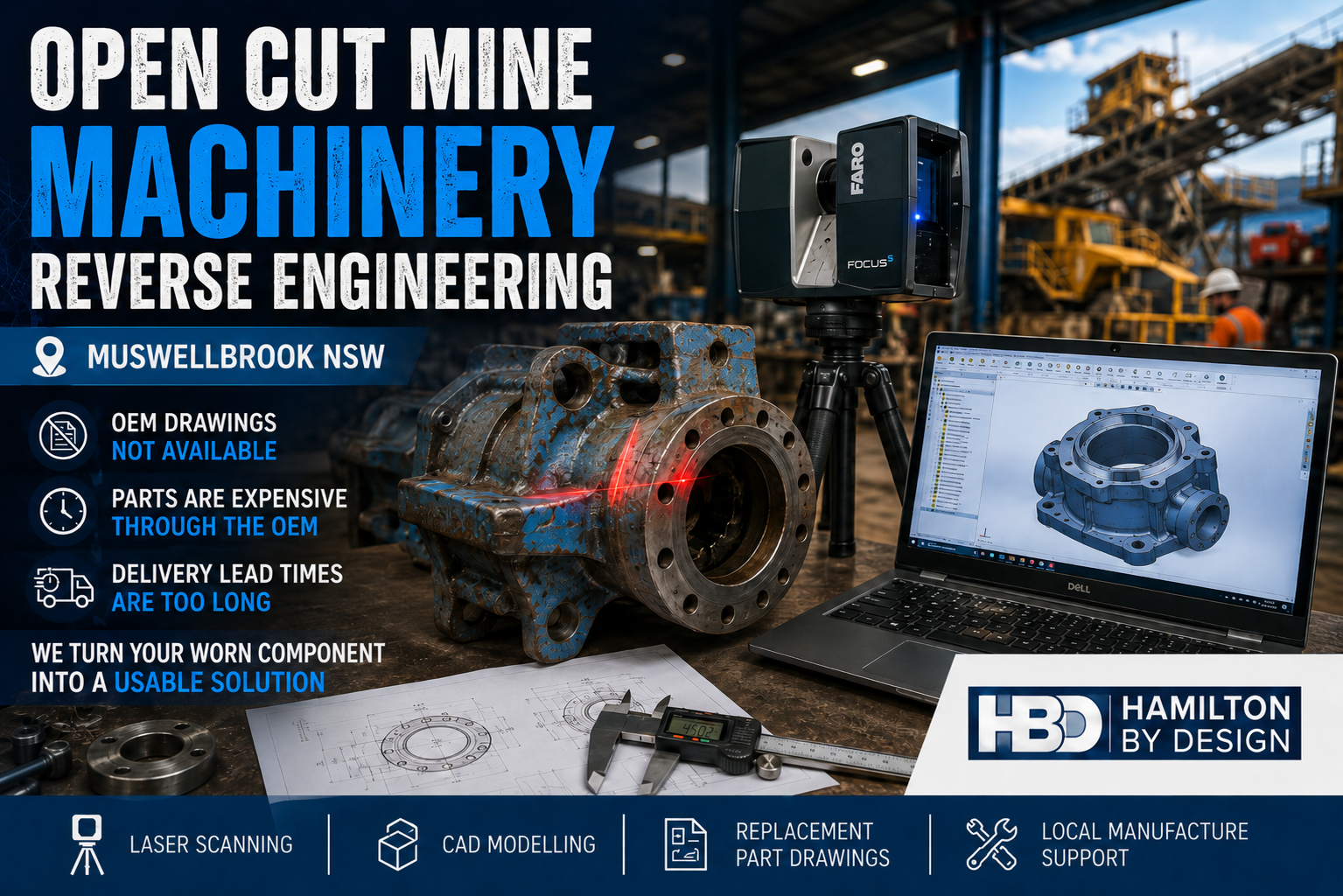


Surface Mine 3D LiDAR Scanning for Hunter Valley, Singleton, Muswellbrook & Upper Hunter NSW

Technical drawing style hero image showing a 3D LiDAR scanner capturing a Hunter Valley surface mine processing plant with conveyors, CHPP structure, pipework, pump station and brownfield mining infrastructure.

Surface Mine 3D LiDAR Scanning for Brownfield Mine Sites

Blue 3D LiDAR scanner icon on a tripod with scanning waves

Surface mines across the Hunter Valley and Upper Hunter are constantly changing. Coal handling plants, conveyors, transfer stations, pump stations, workshops, access platforms, pipework, chutes, bins and rail load-out areas are regularly modified to keep production moving. Some changes are part of planned capital upgrades. Others happen during shutdowns, maintenance windows or urgent repair work.

After years of brownfield modifications, the problem becomes simple: the plant on site no longer matches the drawings.

For surface mine operators, outdated drawings create real engineering and shutdown risk. Engineers may design around old information. Fabricators may manufacture parts that do not fit. Shutdown planners may miss access restrictions, clashes or tie-in issues. Installation crews may arrive on site only to discover that pipework, steelwork, guards, walkways or equipment are not where the drawings say they are.

This is where 3D laser scanning provides real value. By capturing accurate existing-condition data of the installed plant, mine operators and engineering teams can make decisions based on what is actually on site, not what was originally drawn years ago.

Hamilton By Design provides engineering-grade 3D LiDAR scanning, point cloud processing, scan-to-CAD modelling and as-built verification for Hunter Valley surface mines and brownfield industrial sites.

Locations Supported Across the Hunter Valley and Upper Hunter

Hamilton By Design supports surface mine and heavy industrial projects across the Hunter Valley, Upper Hunter and surrounding mining support regions, including:

Singleton, Muswellbrook, Ravensworth, Lemington, Warkworth, Mount Thorley, Broke, Bulga, Camberwell, Hebden, Jerrys Plains, Rixs Creek, Glennies Creek, Maison Dieu, Whittingham, Liddell, Bayswater, Aberdeen, Denman, Scone, Maitland, Cessnock, Lake Macquarie, Newcastle and the Port of Newcastle corridor.

These locations are affected by the same brownfield engineering problem. Mine plant is modified over time, but the drawing register does not always keep up. A conveyor transfer station may have extra guarding. A pump station may have replacement pipework. A CHPP may have modified chutes, platforms, cable trays and access stairs. A rail load-out area may have structural or mechanical changes that are not fully documented.

Hamilton By Design also supports industrial and mining clients beyond the Hunter Valley through 3D laser scanning across Australia, helping project teams capture reliable as-built data for plant upgrades, shutdown planning, fabrication checks and engineering verification.

Why Existing Surface Mine Drawings Become Outdated

Surface mine infrastructure rarely stays the same for long. Production requirements change. Maintenance teams improve access. Process engineers adjust layouts. Shutdown crews replace equipment. Fabricators install revised steelwork. Emergency repairs become permanent. Over time, these small changes create a large difference between the original drawings and the actual plant.

Common causes of outdated drawings include:

Brownfield ChangeResulting Risk
Conveyor upgradesNew chutes, guards or drives may not match old layouts
CHPP modificationsPipework, platforms and equipment positions may change
Pump station changesFlanges, valves and pipe supports may not be in the documented location
Structural access upgradesStairs, ladders, handrails and platforms may have been added or replaced
Shutdown repairsTemporary supports or modifications may become permanent
Replacement equipmentNew motors, pumps, screens or gearboxes may have different footprints
Rail load-out changesStructural and mechanical interfaces may no longer match original drawings
Site services modificationsCable trays, water lines, air lines and drainage may be undocumented

When drawings are unreliable, engineering design becomes slower and riskier. More time is spent checking dimensions, confirming interfaces and resolving clashes. In a shutdown environment, that uncertainty can become expensive very quickly.

What 3D LiDAR Scanning Captures

3D LiDAR scanning captures the existing mine plant as a measured 3D point cloud. The scanner records millions of points from multiple positions, creating a detailed digital record of the installed site condition.

For surface mining projects, LiDAR scanning can capture:

  • Conveyor transfer stations
  • CHPP areas
  • Crusher stations
  • Screens and bins
  • Chutes and hoppers
  • Pump stations
  • Pipework and valve stations
  • Structural steelwork
  • Platforms, stairs, ladders and handrails
  • Workshops and maintenance bays
  • Rail load-out structures
  • Stockpile conveyor systems
  • Water management infrastructure
  • Electrical rooms and cable tray support areas
  • Brownfield tie-in zones

The point cloud can then be used for engineering review, CAD modelling, clash detection, as-built documentation, shutdown planning and fabrication support.

Turning Scan Data into Engineering Information

The scan is only the first step. The real value comes from turning point cloud data into information engineers, fabricators and project teams can use.

Hamilton By Design can convert captured site data into 3D CAD modelling outputs suitable for mechanical layouts, plant upgrades, fabrication planning, clash checking and as-built documentation.

For example, if a mine is planning to replace a chute, the scan can capture the surrounding steelwork, conveyor geometry, access platforms, guards and nearby equipment. The design team can then model the new chute around the actual site conditions. This reduces the chance of a clash during installation.

If a pump station is being modified, LiDAR scanning can confirm the true location of pipework, flanges, valves, supports and access clearances. This helps fabricators produce more accurate spools and reduces the need for site rework.

If a CHPP area has been modified many times, scanning can provide an updated as-built record that engineers can use for future upgrades.

For shutdown projects, the value is even greater. Shutdown windows are limited. Mistakes are costly. If parts do not fit, access is blocked or tie-in points are wrong, the project can lose valuable time. 3D LiDAR scanning helps reduce those unknowns before the shutdown begins.

Typical Deliverables

Hamilton By Design can support surface mine scanning projects with practical engineering deliverables, including:

DeliverablePurpose
Registered point cloudAccurate 3D record of the existing plant
E57 / RCP / RCS / LAS filesPoint cloud formats for CAD and review workflows
3D CAD modelEngineering model of selected plant, equipment or structure
2D GA drawingsPlans, elevations and sections for design and review
Scan-to-CAD modelConverts point cloud data into usable CAD geometry
Clash reviewChecks proposed equipment against existing site conditions
Tie-in verificationConfirms exact positions before fabrication
Shutdown work pack supportHelps planners, engineers and installers understand the site
As-built documentationUpdates records after years of brownfield change

The deliverable should match the engineering problem. Some projects only need a point cloud. Others need a detailed CAD model, fabrication drawings or clash detection review.

Example Project Applications

Surface mine 3D LiDAR scanning is useful for many common Hunter Valley mining projects, including:

  • Conveyor transfer station upgrades
  • Chute replacement and redesign
  • CHPP brownfield modifications
  • Pump station upgrades
  • Pipework replacement and spool verification
  • Access platform and stair upgrades
  • Structural steel verification
  • Crusher and screen area modifications
  • Rail load-out upgrades
  • Workshop and maintenance bay layout changes
  • Shutdown planning and installation checks
  • Reverse engineering of obsolete components
  • As-built documentation for undocumented plant

For worn, modified or undocumented mining equipment, Hamilton By Design can also support reverse engineering for mining and industrial equipment. This is useful where existing parts, structures or assemblies need to be captured, modelled and converted into practical engineering documentation.

Why Use an Engineering-Led Scanning Approach?

Not all scanning is the same. For surface mine projects, the scan needs to support engineering decisions. That means the scanner operator must understand what matters to the design team: tie-in points, access clearances, structural interfaces, equipment footprints, maintenance envelopes, lifting paths and shutdown constraints.

An engineering-led scanning approach focuses on the areas that affect design, fabrication and installation. It is not just about capturing a large point cloud. It is about capturing the right information so the project team can reduce risk.

Hamilton By Design combines 3D LiDAR scanning with mechanical engineering, CAD modelling, drafting and brownfield project experience. This allows the scan data to be turned into practical engineering outputs that support real site work.

Hamilton By Design logo displayed on a blue tilted rectangle with a grey gradient background

Conclusion

Surface mines across the Hunter Valley, Singleton, Muswellbrook and Upper Hunter region often operate with plant that has changed significantly over many years. Drawings may be incomplete, outdated or inconsistent with what is installed on site.

For brownfield mining projects, this creates risk. New equipment can clash with existing plant. Fabricated parts may not fit. Shutdown work can be delayed. Engineering teams may spend too much time checking dimensions manually.

Surface Mine 3D LiDAR Scanning helps solve this problem by capturing accurate as-built data of the existing plant. The point cloud can then be used for CAD modelling, clash checking, shutdown planning, fabrication support and engineering verification.

For Hunter Valley surface mine operators, the message is clear:

If the drawings are no longer reliable, scan the plant before designing, fabricating or installing the next modification.

Talk to Us – Contact Us

Name
Would you like us to arrange a phone consultation for you?
Address

Our clients: