Scan-to-CAD vs Traditional Design Workflows | Which Approach Delivers Better Engineering Outcomes?

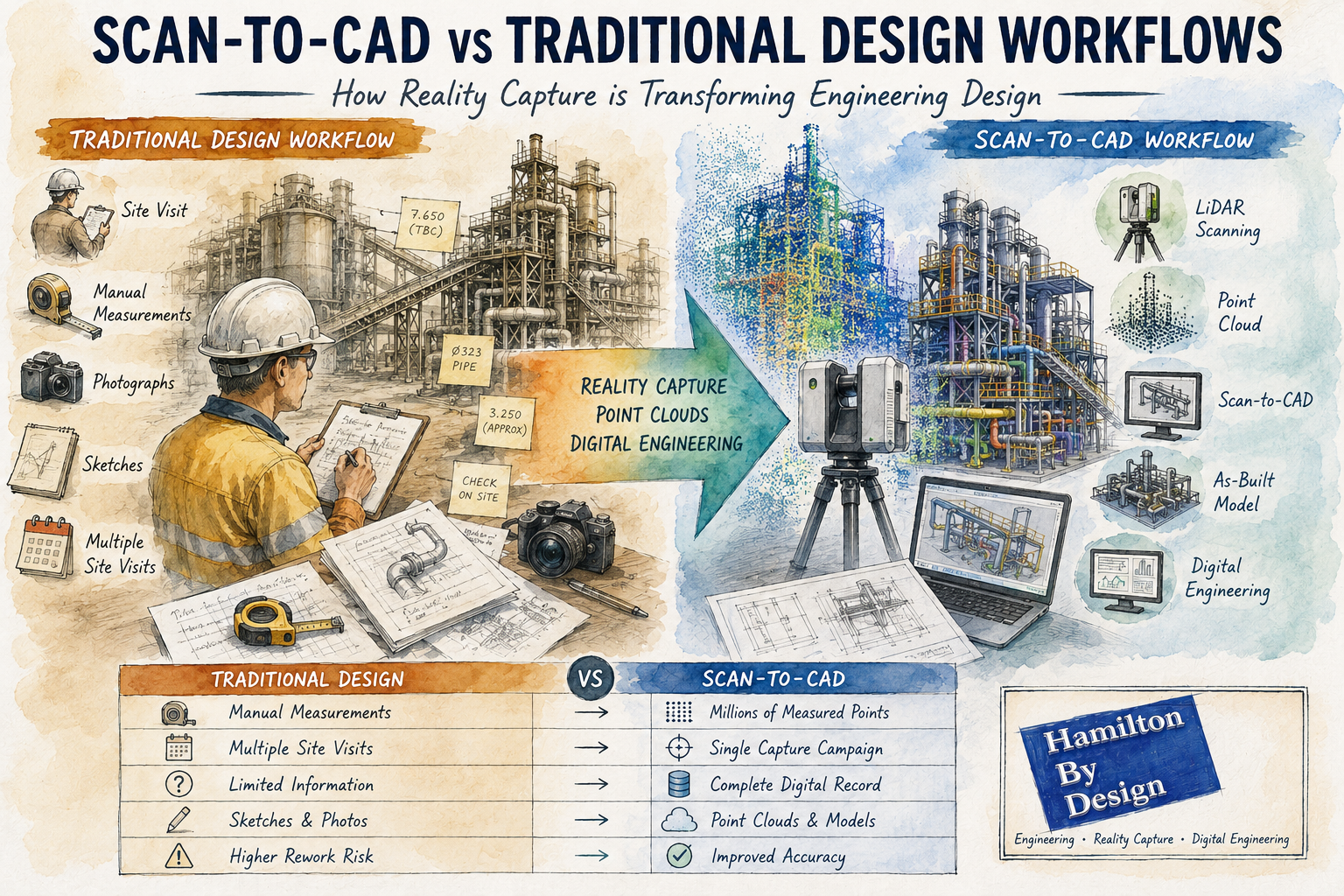
Scan-to-CAD vs traditional design workflows infographic showing LiDAR scanning, point cloud modelling, reality capture and digital engineering for industrial plant design and as-built documentation.

Scan-to-CAD vs Traditional Design Workflows: How Reality Capture is Transforming Engineering Design

For decades, engineering and drafting companies have relied on traditional design workflows to create new assets, modify existing facilities and develop construction documentation. These methods typically involve site visits, manual measurements, photographs, sketches and extensive assumptions about existing conditions.

While traditional design processes have successfully delivered countless projects, modern reality capture technologies are changing how engineering data is collected and utilised.

The introduction of terrestrial LiDAR scanning, engineering-grade reality capture and point cloud modelling has given design companies access to highly accurate representations of existing facilities. Rather than starting with assumptions and limited measurements, engineers can now begin with a digital copy of reality.

This approach is commonly known as Scan-to-CAD.

At Hamilton By Design, we have seen first-hand how Scan-to-CAD workflows can improve project accuracy, reduce site visits and provide better information for engineering decision-making. However, traditional design methods still have an important role to play.

The key is understanding where each approach provides the greatest value.


What is a Traditional Design Workflow?

Traditional design workflows generally begin with a site inspection and manual data collection process.

An engineer, designer or draftsperson visits the facility and records information such as:

  • Dimensions
  • Levels
  • Equipment locations
  • Structural arrangements
  • Pipe routing
  • Building layouts
  • Photographs
  • Sketches

The collected information is then used to develop drawings and 3D models.

A typical workflow may include:

  1. Site visit
  2. Manual measurements
  3. Photographic survey
  4. Sketch preparation
  5. CAD model creation
  6. Design development
  7. Drawing production
  8. Construction issue

This process has been the backbone of engineering design for many years.


Challenges with Traditional Design Methods

Although effective, traditional workflows present several challenges.

Limited Data Collection

No matter how experienced the survey team is, it is impossible to measure everything.

Often only dimensions considered important at the time are collected.

If additional information is required later, another site visit may be necessary.

Human Error

Manual measurements introduce opportunities for error.

Common issues include:

  • Incorrect dimensions
  • Missed measurements
  • Recording errors
  • Inconsistent datum references

These errors can propagate throughout the project.

Access Restrictions

Industrial facilities often contain:

  • Confined spaces
  • Elevated structures
  • Operational equipment
  • Hazardous environments

Obtaining measurements in these areas can be difficult and expensive.

Multiple Site Visits

Many projects require repeated visits to verify dimensions and resolve discrepancies.

This increases:

  • Project costs
  • Travel expenses
  • Programme duration

What is Scan-to-CAD?

Scan-to-CAD is the process of using reality capture technologies to create engineering drawings and models.

The workflow begins with a terrestrial LiDAR scan of the facility.

Millions or billions of measured points are captured to create a highly detailed point cloud.

The point cloud then becomes the foundation for:

  • CAD models
  • BIM models
  • General arrangement drawings
  • Structural models
  • Pipework layouts
  • Reverse engineering projects
  • Asset documentation

Rather than manually measuring selected features, Scan-to-CAD captures the entire environment.


How Scan-to-CAD Works

Step 1 โ€“ Reality Capture

A LiDAR scanner records the existing facility.

This may include:

  • Buildings
  • Process plants
  • Pipework
  • Conveyors
  • Tanks
  • Structural steel
  • Mechanical equipment

Step 2 โ€“ Point Cloud Registration

Individual scans are combined into a unified coordinate system.

The result is a complete digital representation of the site.

Step 3 โ€“ Engineering Review

Engineers review the point cloud and determine project requirements.

Step 4 โ€“ CAD Modelling

Relevant assets are modelled from the point cloud.

Outputs may include:

  • 2D drawings
  • 3D CAD models
  • BIM models
  • Fabrication drawings
  • Construction documentation

Step 5 โ€“ Design Development

The design team develops modifications directly against existing conditions.


Comparing Scan-to-CAD and Traditional Design Workflows

Accuracy

Traditional Workflow

Accuracy depends on:

  • Measurement methods
  • Survey coverage
  • Site conditions
  • Human interpretation

Typically, only selected dimensions are recorded.

Scan-to-CAD

Millions of measured points create a detailed digital representation.

Engineering-grade terrestrial LiDAR scanning can provide highly accurate spatial information across entire facilities.

Winner: Scan-to-CAD


Site Time

Traditional Workflow

Complex facilities may require several site visits.

Scan-to-CAD

Most information is captured during a single scanning campaign.

Winner: Scan-to-CAD


Data Availability

Traditional Workflow

Only measured dimensions are available.

Scan-to-CAD

The entire captured environment remains available for future reference.

Winner: Scan-to-CAD


Upfront Cost

Traditional Workflow

Lower initial survey costs.

Scan-to-CAD

Requires specialised scanning equipment and processing.

Winner: Traditional Workflow


Long-Term Value

Traditional Workflow

Information is often project-specific.

Scan-to-CAD

Point clouds become long-term digital assets.

Winner: Scan-to-CAD


Why Design Companies Are Adopting Scan-to-CAD

Increasingly, engineering consultancies and drafting companies are integrating reality capture into their workflows.

Benefits include:

Reduced Rework

Designs can be developed against actual site conditions.

Improved Clash Detection

Existing assets can be modelled accurately.

Better Stakeholder Communication

Point clouds and digital models improve project visualisation.

Enhanced Project Planning

Engineers can assess access and constructability earlier.

Faster Design Iterations

Additional measurements are often available without returning to site.


Applications Across Industries

Mining

Mining facilities contain extensive:

  • Conveyors
  • Chutes
  • Crushers
  • Tanks
  • Pipework

Scan-to-CAD can significantly improve brownfield modification projects.

Manufacturing

Production facilities frequently evolve over time.

Reality capture provides accurate documentation of current conditions.

Water and Wastewater

Pump stations and treatment plants often contain complex mechanical layouts.

Scan-to-CAD improves upgrade planning and documentation.

Commercial Buildings

Architects and engineers can generate accurate as-built documentation.

Energy

Power stations and industrial utilities benefit from detailed digital asset records.


When Traditional Workflows Still Make Sense

Despite the advantages of reality capture, traditional methods remain valuable.

Examples include:

Concept Design

Early-stage feasibility studies may not require detailed site data.

Greenfield Projects

When designing on vacant land, no existing assets exist to scan.

Small Modifications

Minor changes may not justify scanning costs.

Budget-Constrained Projects

Some projects require a lower-cost approach.

The most successful engineering organisations understand that both approaches have their place.


The Rise of AI-Assisted Scan-to-CAD

Artificial Intelligence is introducing new capabilities into reality capture workflows.

Emerging technologies can:

  • Identify pipework
  • Classify equipment
  • Recognise structural steel
  • Generate preliminary BIM models
  • Accelerate modelling workflows

Although engineering verification remains essential, AI-assisted modelling is expected to become increasingly common.


Digital Twins and Future Design Workflows

The future of engineering design is likely to combine:

  • Reality capture
  • Scan-to-CAD
  • Scan-to-BIM
  • Digital twins
  • Artificial intelligence
  • Cloud collaboration

Rather than creating drawings from limited measurements, engineering teams will increasingly work from comprehensive digital representations of existing assets.

This shift has the potential to improve project quality, reduce risk and accelerate project delivery.


How Hamilton By Design Supports Scan-to-CAD Projects

Hamilton By Design provides engineering-led reality capture and Scan-to-CAD services throughout Australia.

Our capabilities include:

  • Terrestrial LiDAR scanning
  • Engineering-grade reality capture
  • Point cloud registration
  • Scan-to-CAD
  • Scan-to-BIM
  • Reverse engineering
  • Mechanical design
  • Structural drafting
  • Asset documentation
  • Digital engineering support

We work across:

  • Mining
  • Manufacturing
  • Infrastructure
  • Energy
  • Commercial buildings
  • Water and wastewater

Our approach combines practical engineering experience with modern reality capture technology to deliver accurate and usable engineering information.


Hamilton By Design logo displayed on a blue tilted rectangle with a grey gradient background

Traditional design workflows have served the engineering industry well for decades and continue to play an important role in many projects.

However, the emergence of Scan-to-CAD workflows has fundamentally changed how existing facilities can be documented and modelled.

By capturing measured reality rather than relying solely on manual measurements, engineering teams gain access to more complete information, improved accuracy and greater flexibility throughout the design process.

For brownfield projects, industrial facilities and complex infrastructure, Scan-to-CAD is increasingly becoming the preferred method for developing accurate engineering deliverables.

Rather than replacing traditional design workflows, reality capture enhances them, providing engineers and designers with a richer foundation from which to make informed decisions.


Frequently Asked Questions (FAQ)

What is Scan-to-CAD?

Scan-to-CAD is the process of converting LiDAR scan data or point clouds into CAD drawings and 3D models. It allows engineers to develop designs using accurate representations of existing assets.

How accurate is Scan-to-CAD?

Accuracy depends on the scanning equipment and workflow used. Engineering-grade terrestrial LiDAR scanning can provide highly accurate spatial information suitable for engineering and drafting applications.

What industries benefit most from Scan-to-CAD?

Mining, manufacturing, infrastructure, energy, commercial buildings, water treatment facilities and industrial processing plants all benefit from Scan-to-CAD workflows.

Is Scan-to-CAD better than traditional surveying?

Both approaches have value. Scan-to-CAD generally provides more comprehensive site information, while traditional surveying may be appropriate for smaller or less complex projects.

Can point clouds be used directly in CAD software?

Yes. Many CAD platforms can reference point cloud data directly, allowing engineers to model against real-world measurements.

What is the difference between Scan-to-CAD and Scan-to-BIM?

Scan-to-CAD focuses on creating engineering drawings and CAD models, while Scan-to-BIM creates Building Information Models containing both geometry and asset information.

Does Scan-to-CAD reduce site visits?

In many cases, yes. Capturing comprehensive scan data can significantly reduce the need for repeat measurement visits.

Can AI automatically create CAD models from point clouds?

AI-assisted modelling tools are becoming increasingly capable, but engineering review and verification remain essential for accurate project outcomes.

What deliverables can be produced from a Scan-to-CAD project?

Deliverables may include point clouds, CAD models, BIM models, fabrication drawings, as-built drawings, general arrangement drawings and digital twin models.

Why choose Hamilton By Design for Scan-to-CAD projects?

Hamilton By Design combines engineering-led reality capture, practical industry experience and advanced digital engineering workflows to deliver accurate and usable engineering information for industrial and infrastructure projects throughout Australia.


Mechanical Engineering | Structural Engineering

3D LiDAR Scanning Darwin for engineering surveys, laser scanning, reality capture and point cloud modelling services
3D LiDAR Scanning Australia engineering services for laser scanning, reality capture, scan-to-CAD, Scan-to-BIM and as-built documentation across Australia
3D LiDAR scanning services on the Central Coast providing engineering-grade laser scanning, point cloud capture, scan-to-CAD modelling and industrial reality capture for infrastructure and industrial projects.
3D LiDAR Scanning Perth for engineering surveys, laser scanning, reality capture and point cloud modelling services
3D LiDAR Scanning Sydney for engineering surveys, laser scanning, reality capture and point cloud modelling services
3D LiDAR Scanning Brisbane for engineering surveys, laser scanning, reality capture and point cloud modelling services
3D LiDAR Scanning Canberra for engineering surveys, laser scanning, reality capture and point cloud modelling services
3D LiDAR Scanning Newcastle for engineering surveys, laser scanning, reality capture and point cloud modelling services
3D LiDAR Scanning Adelaide for engineering surveys, laser scanning, reality capture and point cloud modelling services

Rockhampton a Unique Environment for Engineering

Why Rockhampton Is a Unique Environment for Engineering & Digital Technology

Rockhampton stands out for several reasons that directly influence how engineering and design work is executed in the region.

1. A City at the Centre of Agriculture, Mining and Defence

Few regional cities in Australia support as many sectors simultaneously:

  • cattle production & feedlots
  • abattoirs and food-processing plants
  • mining workflow (Bowen Basin)
  • fabrication and workshop environments
  • major road & rail logistics
  • defence operations at Shoalwater Bay

This diversity creates an environment where brownfield projects, plant upgrades and operational changes are constant โ€” and where accurate digital engineering is invaluable.

2. A Heritage-Rich Built Environment

Rockhamptonโ€™s colonial architecture and historic precincts add engineering complexity, especially for:

  • renovation and extension planning
  • capturing building geometry
  • ensuring compliance during upgrades
  • modelling concealed or irregular structures

Accurate scanning and modelling reduce the risks associated with modifying older buildings.

3. A Rapidly Growing Industrial Corridor

With expansions across Gracemere, Parkhurst and the Port Alma supply chain, Rockhampton is strengthening its role as a:

  • fabrication hub
  • transport distribution centre
  • industrial service precinct

Digital engineering ensures these facilities deliver maximum efficiency with minimal downtime.


3D LiDAR Laser Scanning: Rockhamptonโ€™s Path to More Accurate, Data-Driven Projects

One of the biggest challenges in Central Queensland is managing complexity in brownfield industrial environments: tight tie-in points, undocumented modifications, legacy equipment, unknown clearances and misaligned plant sections.

This is exactly where 3D LiDAR scanning becomes a game-changing tool.

Hamilton By Design uses engineering-grade scanning to produce:

  • complete as-built environments
  • millimetre-accurate spatial data
  • structural geometry and deflection insights
  • clash detection for new installations
  • alignment checks for equipment
  • precise digital documentation for tendering and fabrication

Learn more about our scanning process here:
3D Laser Scanning โ€“ https://www.hamiltonbydesign.com.au/home/3d-lidar-scanning-digital-quality-assurance/3d-laser-scanning/

For Rockhampton industries, the value is immediate:

  • reduced rework and fewer shutdown overruns
  • accurate fit-up when fabricators install new components
  • better engineering decisions based on real data
  • faster turnaround for designs and feasibility planning

From abattoirs to feed mills, mining workshops to energy infrastructure, LiDAR scanning ensures every project begins with precise, reliable site information.


3D Modelling & Drafting: Turning Reality Into Intelligent Engineering Models

Once the point cloud is captured, Hamilton By Design transforms the data into:

  • SolidWorks parts and assemblies
  • mechanical models for plant upgrades
  • fabrication-ready drawings (GA, detail, isometric & BOMs)
  • structural models for platforms, supports, conveyors and frames
  • mechanical layout concepts and optimisation studies

For Rockhampton businesses, this is particularly valuable because:

  • fabrication teams rely on correct geometry
  • shutdown windows are small
  • misaligned or undocumented equipment is common
  • design changes often must occur quickly

With 3D modelling, plant owners, contractors and fabricators can visualise the project before steel is cut โ€” dramatically improving accuracy and reducing cost.


Mechanical Engineering for Rockhamptonโ€™s Industrial & Agricultural Sectors

Rockhamptonโ€™s diverse economy means the region is constantly upgrading:

  • processing plants
  • abattoirs
  • feed mills
  • grain-handling systems
  • water-treatment infrastructure
  • conveyor systems
  • workshops and industrial machinery

Hamilton By Design provides engineering support such as:

  • mechanical design for new or upgraded equipment
  • structural assessments on frames, platforms, chutes and conveyors
  • vibration, deflection and alignment analysis
  • flow optimisation for materials-handling systems
  • FEA (Finite Element Analysis) for components and assemblies
  • lifting, access and maintenance design

Our engineer-led workflow ensures that every design is based on reality โ€” captured by LiDAR and validated through modelling and analysis.


How Digital Engineering Helps Rockhamptonโ€™s Key Industries

1. Beef Processing & Agri-Food Operations

Rockhamptonโ€™s processing facilities are often complex, space-constrained and continuously operating.

Scanning assists with:

  • plant upgrades
  • layout efficiency studies
  • tie-in accuracy for new conveyors or equipment
  • compliance documentation

2. Bowen Basin Mining Support

Rockhampton is a major hub for:

  • mining contractors
  • fabrication workshops
  • equipment repair
  • maintenance logistics

LiDAR scanning and engineering reduce rework in fabricated components destined for:

  • Moranbah
  • Blackwater
  • Middlemount
  • Dysart and surrounding mines

3. Industrial Precincts & Port Supply Chains

Industrial estates across Parkhurst and Gracemere benefit from:

  • warehouse fit-outs
  • crane runway checks
  • processing-line layout design
  • mechanical and structural upgrades

4. Heritage & Architectural Redevelopment

Scanning enables:

  • accurate modelling of old buildings
  • conflict detection for new internal services
  • faรงade preservation planning

No risk of relying on inaccurate tape-measure surveys.


A Fully Integrated Workflow: Scan โ†’ Model โ†’ Engineer โ†’ Deliver

One of the biggest advantages Hamilton By Design provides to Rockhampton businesses is single-source accountability.

Our streamlined process includes:

  1. 3D LiDAR scanning of the site
  2. Processing & registering point-cloud data
  3. SolidWorks modelling of the environment
  4. Engineering assessments & calculations
  5. Fabrication-ready drawings
  6. Digital QA for installation

Thereโ€™s no handover between scanning companies, designers and engineers โ€” everything is delivered by one team, reducing miscommunication and improving project outcomes.


Rockhamptonโ€™s Future Is Digital โ€” And Weโ€™re Ready to Support It

Rockhampton is experiencing a period of sustained growth driven by agriculture, mining, defence and industrial expansion. As facilities upgrade and capacity increases, accurate engineering data, digital design tools and advanced scanning technology will be central to delivering smarter, safer and more efficient projects.

Hamilton By Design logo displayed on a blue tilted rectangle with a grey gradient background
3D LiDAR scanning and 3D modelling service button โ€” laser scanner capturing a point cloud for engineering and CAD modelling
Mechanical engineering services

Hamilton By Design is proud to support Central Queensland with:

  • 3D LiDAR laser scanning
  • Mechanical engineering consulting
  • 3D modelling and drafting
  • Digital documentation and quality assurance

Whether youโ€™re planning an upgrade to a processing plant, modernising a workshop, designing a conveyor system or documenting an entire facility, our engineering-led team provides the precision and reliability your project needs.

Our Clients

Name
Would you like us to arrange a phone consultation for you?
Address
Finite Element Analysis (FEA) engineering simulation button
Mechanical engineering services

Chute Design at Hamilton By Design

Chute Design at Hamilton By Design

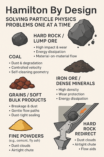
At Hamilton by Design, we see ourselves as more than engineers โ€” we are problem-solvers who bring both science and experience to the table. Every bulk material transfer is unique, and each one carries its own challenges. By combining the principles of particle physics with decades of hands-on site experience, we design chutes and transfer points that perform in the real world, not just on a computer screen.

We are a small, specialised company, not a large corporate machine. That means you deal directly with the people who understand your operation, your materials, and your challenges. We take pride in our ability to stand on-site, watch the flow of material, and recognise behaviours that only years of experience can teach. This gives us the clarity to engineer practical solutions that keep your plant running reliably.

For us, your success is our success. We measure our achievement not by the number of projects we complete, but by the value we add to your operation โ€” less dust, less wear, fewer stoppages, more tonnes moved.

Learn more about our approach and solutions Hamilton By Design – Chute Design


Our clients:

Name
Would you like us to arrange a phone consultation for you?
Address

Mechanical
Engineering
| Structural
Engineering
3D LiDAR scanning and 3D modelling service button โ€” laser scanner capturing a point cloud for engineering and CAD modelling
Mechanical engineering services

Mechanical
Drafting
| Structural
Drafting

3D
Laser Scanning
| 3D
CAD Modelling
| 3D
Scanning

SolidWorks
Contractors in Australia

Hamilton By Design โ€“ Blog

Consulting Engineers

About Us โ€“
Hamilton By Design

Designing for Developing Hazards: Lessons from the Derrimut Crane Collapse

Designing for Developing Hazards

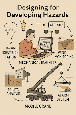
Crane accidents are among the most visible reminders of the risks inherent in construction. The collapse of a crane at a data centre site in Derrimut, Melbourne, brought attention once again to the vulnerability of temporary lifting structures. While formal investigations are still underway, and no conclusions should be drawn prematurely, the event provides a valuable opportunity for reflection within the engineering community.

This article considers the collapse not as an isolated failure but as a case study in hazard identification. In particular, it highlights how mechanical engineers must adapt from a static, design-phase view of risk to a dynamic, real-time approach to hazard monitoring. Wind, soil stability, and load conditions are well-known hazards. But with modern tools โ€” including LiDAR scanning for obstacle detection โ€” engineers can move toward a future where developing hazards are continuously tracked, anticipated, and controlled.

From Hazard Identification to Live Hazard Monitoring

Hazard identification has traditionally been a design-phase process: engineers anticipate risks, apply safety factors, and create conservative margins. This remains essential. Yet the Derrimut collapse illustrates the limits of a static model in a dynamic environment.

Cranes are exposed to evolving hazards:

  • Wind gusts that change minute by minute.
  • Soil stability that shifts with rainfall, excavation, or groundwater.
  • Obstacles such as power lines or nearby structures, which can create cascading risks if struck.
  • Load dynamics, including swinging or sudden movement.

What is needed is a transition from hazard identification to hazard monitoring: a continuous loop where design assumptions are validated against real-time data, and where developing risks are detected before they become failures.

Wind Hazards: Predicting the Unpredictable

Wind is a leading cause of crane collapses. Engineers know the mathematics: pressure rises with the square of velocity. A 50 km/h gust exerts twice the force of a 35 km/h breeze.

Most cranes today are fitted with anemometers and alarms, but these are often basic: a single reading at a single point, with alarms sounding when preset thresholds are exceeded. This approach can miss:

  • Local gust variability along a long jib.
  • Interaction with crane orientation (wind hitting the broadside is more critical than aligned wind).
  • Forecasted conditions that could deteriorate within minutes.

Next-generation wind monitoring could include:

  • Multi-point sensor arrays on cranes.
  • Integration with Bureau of Meteorology gust forecasts.
  • AI models predicting when risk thresholds will be exceeded, not just reporting when they are crossed.
  • Automatic crane repositioning to minimise wind exposure.

This transforms alarms from reactive to predictive โ€” the difference between warning after a hazard is present and anticipating before it materialises.


Soil Hazards: Stability Under Load

Ground conditions are another silent but critical hazard. Outriggers may impose hundreds of kilonewtons on pads, meaning even small soil weaknesses can lead to tilting or overturning.

Engineering practice already includes soil investigations: boreholes, CPT, SPT, and FEA models. But these tests capture conditions before installation, not necessarily during operation. Soil strength can change due to rainfall, groundwater shifts, or nearby excavation.

Live soil monitoring can be achieved with:

  • Load cells under mats to track ground reactions.
  • Settlement gauges to detect tilt.
  • Piezometers for pore pressure during rain events.
  • Integrated warnings when ground resistance trends downward.

This approach acknowledges soil as a living hazard that changes daily.

LiDAR and Obstacle Detection: Power Lines and Proximity Hazards

One striking feature of the Derrimut collapse was the craneโ€™s boom striking power lines. Contact with utilities is a recurrent hazard in crane operations worldwide. While operators are trained to maintain exclusion zones, in practice visibility, fatigue, or unexpected boom movement can still lead to contact.

LiDAR scanning offers a solution.

  • How it works: LiDAR (Light Detection and Ranging) emits laser pulses to map surroundings in 3D with centimetre accuracy. Mounted on a crane, it can create a live digital map of nearby obstacles.
  • Application in cranes:
    • Detecting and mapping power lines, buildings, or scaffolding in the lift path.
    • Setting proximity alarms when a boom, hook, or load approaches a defined clearance.
    • Combining with wind data to predict if gusts could push the load into restricted zones.

In aviation, LiDAR and radar-based systems are standard for obstacle detection. In construction, adoption is patchy. Yet the technology exists, is cost-effective, and could dramatically reduce risks of contact with hazards like live power lines.

LiDARโ€™s strength lies not only in static mapping but in detecting movement โ€” for example, when a suspended load begins to swing toward a power line due to a gust. This is a quintessential developing hazard, one that static design could never fully capture.

Integrated Hazard Dashboards

Wind, soil, and LiDAR obstacle detection all provide valuable data. But their true power lies in integration. Imagine a crane operatorโ€™s cabin equipped with a single dashboard displaying:

  • Wind speeds and gust forecasts, colour-coded for risk.
  • Soil reaction forces under each outrigger, with alerts if settlement is trending.
  • LiDAR mapping of nearby structures and power lines, with real-time clearance zones.
  • Predictive risk models showing probability of instability or contact over the next 30 minutes.

This integration mirrors aviationโ€™s cockpit: multiple inputs fused into actionable guidance. For cranes, such systems could shift the operatorโ€™s role from reactive decision-maker to proactive risk manager.


AI as a Predictive Partner

Artificial Intelligence has a natural role in hazard monitoring:

  • Sensor fusion: combining wind, soil, and LiDAR inputs into coherent risk profiles.
  • Prediction: learning from past crane incidents to forecast when risks are likely to escalate.
  • Decision support: providing operators with clear options (โ€œsafe to continue lift for 20 minutesโ€ / โ€œhalt operations โ€” clearance margin < 1mโ€).

The challenge is balance. AI should not replace human oversight, but augment it. Over-reliance could create new vulnerabilities if operators become complacent. The design challenge is to build AI into systems that support human judgment rather than substitute for it.


Ethics and Engineering Responsibility

The Derrimut collapse underscores the ethical responsibility of mechanical engineers. Hazard identification is not just a design requirement; it is a matter of public safety. The profession has a duty to anticipate, detect, and control risks wherever possible.

The tools now exist to monitor developing hazards โ€” wind sensors, soil gauges, LiDAR scanners, and AI dashboards. If lives and infrastructure can be protected through wider adoption of these tools, then the question becomes one of responsibility: should they be optional, or mandatory?

Open Questions for the Future

  1. Would integrated live monitoring have reduced the risks at Derrimut?
  2. Should all cranes be fitted with LiDAR obstacle detection as standard?
  3. Do we already have enough technology, but lack regulation and enforcement?
  4. What role should AI play in balancing predictive insight with operator autonomy?

The Derrimut incident remains under investigation. No conclusions can be drawn about its specific cause until findings are published. Yet as a case study, it illustrates the broader point that hazards in crane operations are dynamic. Wind, soil, obstacles, and loads evolve minute by minute.

Mechanical engineers have the tools โ€” wind sensors, soil monitors, LiDAR scanners, integrated dashboards, and AI โ€” to detect these developing hazards. The challenge is to move from a culture of static design assumptions to one of continuous hazard monitoring.

The ultimate professional question is this: If aviation can integrate multiple systems to monitor and predict hazards, why canโ€™t construction do the same for cranes? And if we can, how soon will we accept the ethical responsibility to make it standard?

References and Further Reading

  • ISO 4301 / AS 1418 โ€” Crane standards covering stability and wind.
  • ISO 12480-1:2003 โ€” Safe use of cranes; includes environmental hazard monitoring.
  • WorkSafe Victoria Guidance Notes โ€” Crane safety management.
  • Holickรฝ & Retief (2017) โ€” Probabilistic treatment of wind action in structural design.
  • Nguyen et al. (2020) โ€” Real-time monitoring of crane foundation response under variable soil conditions.
  • Liebherr LICCON โ€” Example of integrated load and geometry monitoring.
  • FAA LLWAS โ€” Aviationโ€™s real-time wind shear alert system, model for construction.
  • Recent research in LiDAR obstacle detection (e.g., IEEE Transactions on Intelligent Transportation Systems) โ€” showing LiDARโ€™s potential in complex environments.
Hamilton By Design logo displayed on a blue tilted rectangle with a grey gradient background
3D LiDAR scanning and 3D modelling service button โ€” laser scanner capturing a point cloud for engineering and CAD modelling
Mechanical engineering services

Our clients:

Name
Would you like us to arrange a phone consultation for you?
Address

Structural Drafting

3D CAD Modelling Australia service banner for Hamilton By Design
Australian Drafting logo featuring bold white text reading "Australian Drafting" centred on a blue rounded rectangle background.
Engineering Governance title graphic featuring bold white text reading "Engineering Governance" centred on a blue rounded rectangle background.
Mechanical, Structural & Pipework Drafting service banner by Hamilton By Design featuring white text on a blue background.
Mechanical engineering services
Blue rounded button with the text โ€œSolidWorks Designโ€ in white.
Finite Element Analysis (FEA) engineering simulation button
3D LiDAR Scanning Darwin for engineering surveys, laser scanning, reality capture and point cloud modelling services
3D LiDAR Scanning Australia engineering services for laser scanning, reality capture, scan-to-CAD, Scan-to-BIM and as-built documentation across Australia
3D LiDAR scanning services on the Central Coast providing engineering-grade laser scanning, point cloud capture, scan-to-CAD modelling and industrial reality capture for infrastructure and industrial projects.
3D LiDAR Scanning Perth for engineering surveys, laser scanning, reality capture and point cloud modelling services
3D LiDAR Scanning Sydney for engineering surveys, laser scanning, reality capture and point cloud modelling services
3D LiDAR Scanning Brisbane for engineering surveys, laser scanning, reality capture and point cloud modelling services
3D LiDAR Scanning Canberra for engineering surveys, laser scanning, reality capture and point cloud modelling services
3D LiDAR Scanning Newcastle for engineering surveys, laser scanning, reality capture and point cloud modelling services
3D LiDAR Scanning Adelaide for engineering surveys, laser scanning, reality capture and point cloud modelling services

Mechanical Drafting

3D Laser Scanning

Mechanical Engineering

Consulting Engineers

3D Modelling with You Now โ€” and 3D Modelling in the Future

ย 3D Modellingย 

By Hamilton By Design | www.hamiltonbydesign.com.au

In the 1980s through to the early 2000s, AutoCAD ruled
supreme. It revolutionised the way engineers and designers approached 2D
drafting, enabling technical drawings to be created and shared with speed and
precision across industries. For two decades, it set the benchmark for visual
communication in engineering and construction. But that era has passed.

Today, we live and work in a three-dimensional world โ€” not
only in reality, but in design.

From 2D Drafting to Solid Modelling: The New Standard

At Hamilton By Design, we see 3D modelling not just
as a tool, but as an essential evolution in how we think, design, and
manufacture. The transition from 2D lines to solid geometry has reshaped the
possibilities for every engineer, machinist, and fabricator.

With the widespread adoption of platforms like SolidWorks,
design engineers now routinely conduct simulations, tolerance analysis, motion
studies, and stress testing โ€” all in a virtual space before a single part is
made. Companies like Tesla, Ford, Eaton, Medtronic,
and Johnson & Johnson have integrated 3D CAD tools into their
product development cycles with great success, dramatically reducing rework,
increasing precision, and accelerating innovation.

Where 2D design was once enough, now solid models drive
machining
, laser cutting, 3D printing, automated
manufacturing
, and finite element analysis (FEA) โ€” all from a single
digital source.

A Growing Ecosystem of Engineering Capability

It’s not just the software giants making waves โ€” a global
network of specialised engineering services is helping bring 3D design to life.
Companies like Rishabh Engineering,
Shalin Designs, CAD/CAM Services Inc., Archdraw Outsourcing,
and TrueCADD provide design and
modelling support to projects around the world.

At Hamilton By Design, we work with and alongside these
firms โ€” and others โ€” to deliver scalable, intelligent 3D modelling solutions to
the Australian industrial sector. From laser scanning and site
capture
to custom steel fabrication, we translate concepts into
actionable, manufacturable designs. Our clients benefit not only from our
hands-on trade knowledge but also from our investment in cutting-edge tools and
engineering platforms.

So Whatโ€™s Next? The Future Feels More Fluid Than Solid

With all these tools now at our fingertips โ€” FEA simulation,
LiDAR scanning, parametric modelling, cloud collaboration โ€” the question
becomes: what comes after 3D?

Weโ€™ve moved from pencil to pixel, from 2D lines to
intelligent digital twins. But now the line between design and experience
is beginning to blur. Augmented reality (AR), generative AI design, and
real-time simulation environments suggest that the next wave may feel more
fluid than solid
โ€” more organic than mechanical.

Weโ€™re already seeing early glimpses of this future:

  • Generative
    design tools that evolve geometry based on performance goals
  • Real-time
    digital twins updating with sensor data from operating plants
  • AI-driven
    automation that simplifies design iterations in minutes, not days

In short: the future of 3D design might not be โ€œ3Dโ€ at all
in the traditional sense โ€” it could be interactive, immersive, adaptive.

At Hamilton By Design โ€” Weโ€™re with You Now and into the
Future

Whether youโ€™re looking to upgrade legacy 2D drawings,
implement laser-accurate reverse engineering, or develop a full-scale 3D model
for simulation or manufacturing โ€” Hamilton By Design is here to help.

We bring hands-on trade experience as fitters, machinists,
and designers, and combine it with the modern toolset of a full-service
mechanical engineering consultancy. We’re not just imagining the future of
design โ€” we’re building it.

Letโ€™s design smarter. Letโ€™s think in 3D โ€” and beyond.

Hamilton By Design logo displayed on a blue tilted rectangle with a grey gradient background
3D LiDAR scanning and 3D modelling service button โ€” laser scanner capturing a point cloud for engineering and CAD modelling
Mechanical engineering services

Our clients:

Name
Would you like us to arrange a phone consultation for you?
Address
Finite Element Analysis (FEA) engineering simulation button
Mechanical engineering services

Maximizing Equipment Efficiency with ISO 18436.2 Maintenance Strategies

At Hamilton By Design, we know that keeping your equipment running efficiently isnโ€™t just about quick fixes; itโ€™s about adopting the right maintenance strategies to ensure long-term reliability and performance. With advancements in condition monitoring and diagnostic techniques, the ISO 18436.2 standard has become a cornerstone for effective maintenance practicesโ€”and itโ€™s at the heart of how we help our clients optimize their operations.

In this blog post, weโ€™ll explore the major maintenance strategies aligned with ISO 18436.2 and how they can transform your plantโ€™s productivity.


What is ISO 18436.2?

ISO 18436.2 is an internationally recognized standard that defines the competencies required for personnel performing condition monitoring and diagnostics. It focuses on advanced tools like vibration analysis, helping engineers identify equipment issues before they lead to costly downtime.

At Hamilton By Design, our team is ISO 18436.2-certified, meaning we bring the highest level of expertise to your maintenance needs.


Maintenance Strategies That Deliver Results

ISO 18436.2 aligns with several key maintenance strategies designed to improve reliability, minimize downtime, and optimize equipment performance. Hereโ€™s how they work:

1. Reactive Maintenance

Reactive maintenance is the traditional โ€œrun-to-failureโ€ approach where repairs are made after a breakdown. While not ideal for critical assets, tools like vibration analysis can still play a role by identifying root causes post-failure. This can help inform more proactive strategies in the future.

2. Preventive Maintenance (PM)

Preventive maintenance involves scheduling regular maintenance tasks to prevent failures. While effective to some extent, PM can lead to over-maintenance. By incorporating vibration analysis and other condition monitoring techniques, preventive measures can be more precisely targeted, reducing unnecessary downtime.

3. Condition-Based Maintenance (CBM)

Condition-Based Maintenance uses real-time equipment data to identify issues as they arise. This strategy is central to ISO 18436.2 and includes tools like vibration analysis, thermography, and ultrasonic testing. CBM ensures that maintenance is performed only when necessary, saving time and money.

Benefits:

  • Reduces unplanned downtime.
  • Optimizes maintenance schedules.
  • Extends equipment lifespan.

4. Predictive Maintenance (PdM)

Predictive Maintenance takes CBM a step further, using data trends and analytics to predict when failures are likely to occur. With the expertise of ISO 18436.2-certified personnel, PdM uses advanced tools to detect subtle signs of wear or stress, allowing for intervention before a problem becomes critical.

Key Tools:

  • Vibration analysis for early detection of imbalance or misalignment.
  • Infrared thermography to spot heat anomalies.
  • Ultrasonic testing to identify leaks and material defects.

5. Reliability-Centered Maintenance (RCM)

RCM focuses on understanding the specific failure modes of critical assets and tailoring maintenance strategies accordingly. This approach integrates condition monitoring insights to prioritize tasks that align with operational goals.

Benefits:

  • Aligns maintenance efforts with production priorities.
  • Reduces the risk of unexpected equipment failures.

6. Proactive Maintenance

Proactive maintenance identifies and addresses root causes of recurring issues. By analyzing data from vibration and other diagnostic tools, engineers can resolve underlying problems like misalignment, improper lubrication, or material fatigue.

Impact:

  • Prevents repetitive failures.
  • Improves long-term equipment reliability.

7. Total Productive Maintenance (TPM)

TPM involves a plant-wide effort, from operators to management, to ensure optimal equipment effectiveness. ISO 18436.2-certified personnel can support TPM by providing actionable condition monitoring insights and training operators in basic diagnostic techniques.


How Hamilton By Design Helps

At Hamilton By Design, we bring these strategies to life through tailored maintenance solutions that align with your plantโ€™s needs. Hereโ€™s how we can help:

1. Advanced Condition Monitoring:
Our team uses state-of-the-art tools to monitor equipment health, including vibration analysis, thermography, and ultrasonic testing.

2. Tailored Maintenance Plans:
Every plant is unique. We develop maintenance strategies based on your specific equipment, production goals, and operational priorities.

3. Expert Training and Certification:
We empower your team by offering ISO 18436.2 training, giving them the skills to sustain and enhance maintenance programs.

4. Ongoing Support:
Maintenance is a journey, not a destination. We provide continuous support to refine and optimize your practices as your operations evolve.


The Hamilton By Design Advantage

Adopting advanced maintenance strategies aligned with ISO 18436.2 isnโ€™t just about improving equipment reliabilityโ€”itโ€™s about unlocking greater productivity and profitability for your business.

With our expertise, you can transition from reactive to predictive maintenance, reduce unplanned downtime, and extend the lifespan of your critical assets.

Ready to take your plantโ€™s maintenance strategy to the next level? Contact Hamilton By Design today to find out how we can help.

3D LiDAR scanning and 3D modelling service button โ€” laser scanner capturing a point cloud for engineering and CAD modelling
Mechanical engineering services

Visit us at: www.hamiltonbydesign.com.au
Email us: sales@hamiltonbydesign.com.au
Call us: +61 0477 002 249


Hamilton By Design | Transforming Maintenance | Elevating Performance | Mechanical Engineering

Name
Would you like us to arrange a phone consultation for you?
Address
3D CAD Modelling Australia service banner for Hamilton By Design
3D LiDAR scanning and 3D modelling service button โ€” laser scanner capturing a point cloud for engineering and CAD modelling
Mechanical engineering services
Mechanical drafting services button
Blue rounded button with the text โ€œSolidWorks Designโ€ in white.
Blue banner graphic displaying the text "Point Cloud to CAD - Australia" in large white lettering, representing point cloud processing, scan-to-CAD conversion and digital engineering services across Australia.
Mechanical, Structural & Pipework Drafting service banner by Hamilton By Design featuring white text on a blue background.
Engineering Governance title graphic featuring bold white text reading "Engineering Governance" centred on a blue rounded rectangle background.


Mining Plant Upgrades promotional graphic with bold white text on a blue background representing mining infrastructure, plant improvement, and engineering upgrade projects.

3D Pipework promotional graphic with bold white text on a blue background representing pipework design, modelling, drafting, and engineering services.

Australian Drafting logo featuring bold white text reading "Australian Drafting" centred on a blue rounded rectangle background.
3D Pipework promotional graphic with bold white text on a blue background representing pipework design, modelling, drafting, and engineering services.

Mining Plant Upgrades promotional graphic with bold white text on a blue background representing mining infrastructure, plant improvement, and engineering upgrade projects.

3D LiDAR Scanning for Engineering Projects title graphic featuring bold white text on a blue rounded rectangle background.

Australian Drafting logo featuring bold white text reading "Australian Drafting" centred on a blue rounded rectangle background.
Engineering Governance title graphic featuring bold white text reading "Engineering Governance" centred on a blue rounded rectangle background.



Mechanical, Structural & Pipework Drafting service banner by Hamilton By Design featuring white text on a blue background.
Mechanical engineering services
Blue rounded button with the text โ€œSolidWorks Designโ€ in white.
Finite Element Analysis (FEA) engineering simulation button

3D Scanning Sydney banner promoting engineering-grade 3D laser scanning, LiDAR scanning, and reality capture services by Hamilton By Design.
Mechanical Engineering Sydney banner with white text on a blue background representing Hamilton By Design's mechanical engineering services in Sydney.
Mechanical Drafting and 3D Modelling Sydney banner highlighting Hamilton By Design's CAD drafting, 3D modelling, and engineering design services in Sydney.

Mechanical Engineering | Structural Engineering