3D Laser Scanning & Mechanical Engineering Solutions
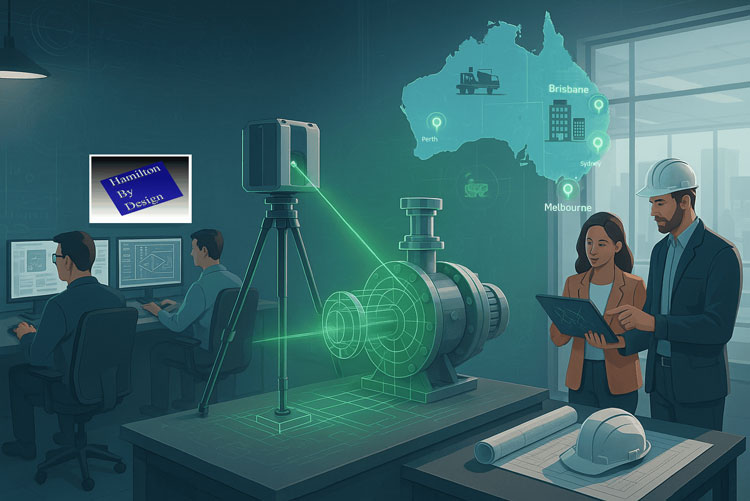
In today’s fast-paced engineering and construction industries, precision and efficiency are everything. Whether you’re managing a large-scale infrastructure project in Brisbane, creating a mechanical prototype in Perth, or needing accurate as-built data for a site in the Hunter Valley, 3D laser scanning and expert mechanical design services are game changers.
At Hamilton Design, we specialise in connecting cutting-edge scanning technology with skilled mechanical designers and structural drafting services to deliver seamless, accurate solutions for every stage of your project.
The Power of 3D Laser Scanning
3D laser scanning is transforming the way engineers, architects, and manufacturers work. By capturing millions of data points with millimetre accuracy, laser scanning creates a highly detailed 3D representation of your asset, site, or structure.
Our team provides 3D laser scanning services in Perth, Brisbane, and Melbourne, as well as laser scanning in the Hunter Valley, helping clients save time and avoid costly rework. This technology is ideal for:
Capturing as-built conditions before design or construction.
Supporting plant upgrades and facility expansions.
Documenting heritage structures and complex geometries.
Reducing site visits with accurate digital models.
Reverse Engineering & Mechanical Design
In addition to scanning, we offer reverse engineering services in Perth and beyond. By combining point cloud data with CAD modelling, we can recreate components, optimise designs, and prepare manufacturing-ready files.
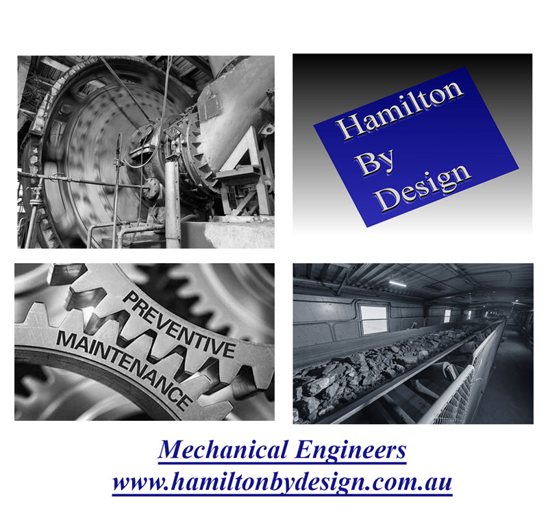
Our mechanical engineers and mechanical designers bring years of experience in 3D mechanical engineering, design and manufacturing mechanical engineering, and problem-solving for a wide range of industries. From bespoke machinery to process equipment, we deliver solutions that work.
Structural Drafting & Project Support
No project is complete without clear, accurate documentation. Our skilled drafters in Hamilton and across Australia provide high-quality structural drafting services that integrate seamlessly with your workflows.
Whether you need shop drawings, fabrication details, or BIM-ready models, our team ensures every line and dimension is correct — saving you time and cost on-site.
Why Choose Hamilton Design?
Nationwide Reach: Serving clients with 3D scanning services in Perth, Brisbane, and Melbourne, and supporting projects in the Hunter Valley.
Complete Solutions: From scanning to modelling to mechanical engineering design.
Accuracy & Efficiency: Reduce project risk and improve decision-making with reliable data.
Experienced Team: Skilled mechanical engineers and drafters who understand your industry.
Ready to Get Started?
If you’re looking for mechanical engineering companies that deliver precision, innovation, and reliability, Hamilton Design is ready to help. Whether you need laser scanning in Perth or Brisbane, structural drafting, or full mechanical design services, our team can support your next project from concept to completion.
📞 Contact us today to discuss your project requirements and find out how our 3D laser scanning and mechanical engineering design solutions can save you time and money.
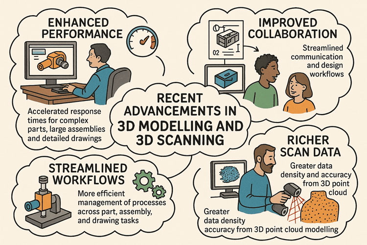
Collaboration is increasingly centred around 3D data. Modern platforms now let teams review, comment on, and markup native 3D models directly inside the design environment. Instead of relying solely on screenshots or static drawings, stakeholders can spin, section, and measure live models for better context. Real-time update notifications and cloud-connected revision control ensure that scanned 3D data and parametric CAD models stay synchronized — critical when working with reality capture data that represents the as-built environment. Hybrid data management options combine local PDM systems with cloud platforms, supporting distributed teams handling massive point clouds or mesh data. This tight integration means that model changes — whether from new design iterations or updated scans — propagate instantly across the project team. Decision-making becomes more visual and informed, keeping everyone aligned around a single, authoritative 3D dataset. Collaboration is no longer a separate process but embedded into daily 3D workflows.
2. Smarter Part Modelling
3D modelling tools are now more intelligent and better suited for working with scan-derived geometry. Designers can quickly apply chamfers, fillets, and shells across complex surfaces, even those imported from meshes or point cloud extractions. Automated bend notch creation and sheet metal tools are optimized to work with geometry derived from scanning existing parts, making reverse-engineering and fabrication preparation much faster. Reference geometry patterning allows engineers to build parametric frameworks over point cloud regions, speeding up master model creation. Cleanup utilities now support selectively removing unnecessary features or smoothing noisy scan data without rebuilding the entire model history. These advances turn what used to be a labour-intensive process into a streamlined workflow that transforms raw reality capture data into production-ready models. The focus is on reducing friction between physical and digital — allowing engineers to move quickly from scan to design, then to manufacturing.
3. Large Assembly Performance
Point cloud and mesh datasets are often extremely large, so performance improvements are critical. Modern CAD platforms now handle assemblies containing both traditional parametric models and massive scan data without bringing systems to a crawl. Engineers can duplicate components while maintaining mates, overlay scans onto assemblies to check fit, and perform interference detection even in lightweight modes. Visualization performance has been tuned for high-density point clouds, allowing smooth pan, zoom, and rotate interactions even with billions of points. Simplification and decimation tools let users strip out unneeded scan detail for faster load times while retaining critical geometry. Seamless transitions between lightweight review and full edit mode make it possible to work interactively with scanned environments. This capability is especially valuable for plant layout, construction validation, and retrofitting projects, where the ability to handle large, mixed-format 3D datasets directly within assemblies is a competitive advantage.
4. Enhanced Drawings and Documentation
Although 3D is the primary medium, 2D documentation remains essential — especially for suppliers and manufacturing partners. Modern CAD environments generate drawings directly from parametric models or scan-based reconstructions, ensuring that documentation matches the latest as-built conditions. Multi-approval stamps, BOM quantity overrides, and standards compliance tools make it easy to document parts created from reverse engineering or field measurement data. Automatic view generation and model-based definition (MBD) help reduce the reliance on fully manual drawings, embedding dimensions and tolerances directly into the 3D model where possible. For projects using scans, section views can be cut through the point cloud or mesh to produce accurate reference drawings without redrawing geometry. These improvements ensure that documentation is both faster to produce and more accurate — giving fabrication teams confidence that the deliverables reflect real-world conditions rather than idealized design intent.
5. Seamless ECAD/MCAD Integration
The convergence of 3D scanning and electronics integration is enabling more precise mechatronic design. Point cloud models of housings, enclosures, and factory floors can be combined with PCB outlines and component data for fit validation. Modern tools allow importing copper traces, vias, and keep-out regions into the mechanical model to run thermal or clearance checks directly against scanned geometry. This prevents collisions and ensures proper heat management early in the design cycle. Real-time synchronization between ECAD and MCAD domains means that if a scanned housing reveals unexpected tolerances, electrical designers can adjust their board layout accordingly. The result is a more accurate digital twin that accounts for both the designed and as-built states. This tighter integration avoids costly late-stage changes, shortens time-to-market, and ensures that mechanical and electrical systems are developed with a shared, reliable 3D reference that reflects physical reality.
6. Performance and Visualization
Visualization is where 3D scanning truly shines. GPU-accelerated engines now render massive point clouds, meshes, and parametric geometry in real time, allowing teams to virtually “walk through” captured environments or inspect reverse-engineered parts at full fidelity. Silhouette-based defeature tools can strip away irrelevant details while maintaining enough geometry for accurate reviews and clash detection. Cached mass property calculations extend to mesh and hybrid models, giving accurate weight and center of gravity data even from scan-derived parts. Photorealistic rendering using real-time ray tracing allows stakeholders to experience designs exactly as they will look, bridging the gap between scanned reality and proposed modifications. This level of visual fidelity improves collaboration, reduces the need for physical mock-ups, and accelerates stakeholder buy-in. High-quality 3D visualization is no longer a luxury — it is a daily tool for engineers, designers, and decision-makers alike.
7. Future Outlook
The future of 3D modelling is increasingly driven by AI and reality capture. Expect CAD platforms to automatically recognize features within point clouds — holes, slots, threads — and generate parametric features with minimal user input. Cloud-native workflows will make it easier to process extremely large scan datasets without local performance bottlenecks. Automated drawing generation and model-based definition will continue to reduce documentation overhead, while digital twin technology will tie live sensor data to scanned geometry for ongoing validation. Generative design powered by AI will be able to work directly with scanned environments, proposing optimized solutions that account for real-world constraints. This convergence of scanning, modelling, and simulation promises a future where physical and digital coexist seamlessly — enabling engineers to capture, design, simulate, and validate with unprecedented speed and accuracy, ultimately transforming how products, factories, and infrastructure are created and maintained.
Operation, Design Challenges, and the Role of Direct Drive Units In the highly demanding and regulated world of underground coal mining, the reliable and efficient transport of coal from the mining face to the surface is critical. Among the many systems involved in this process, conveyor drives play a pivotal role. These systems are tasked with powering conveyor belts that haul coal over long distances through often confined and hazardous environments. A vital part of this setup includes the use of direct drive units (DDUs), particularly in low-profile applications such as underground operations.
This document explores the functionality of conveyor drives in underground coal mines, the unique challenges faced in their operation, the complexities design engineers encounter in their development, and the concept of the phase “outbye”—a term widely used in underground mining to describe the direction and location of operations.
Conveyor Drives in Underground Coal Mining
A conveyor drive is a mechanical system that powers conveyor belts used to transport materials, in this case, coal. In underground mines, these conveyor belts often run for several kilometers, extending from the coal face (the area where coal is actively being cut and mined) to the shaft or drift that brings the coal to the surface.
The drive systems can be located at several points along the belt:
Head drive: Located at the discharge end of the conveyor.
Tail drive: Located at the loading end.
Mid-belt drives: Installed partway along long conveyors to help manage torque and reduce belt tension.
In the context of underground coal mines, the term “conveyor drive” is generally associated with the head or tail drive unit, which powers the movement of the belt.
Role of Direct Drive Units (DDUs)
Direct Drive Units are electric motors directly coupled to the drive shaft of the conveyor pulley, eliminating the need for intermediary gearboxes or belt drives. These units are especially advantageous in underground mining due to their compact design, reliability, and reduced maintenance.
Benefits of DDUs in Underground Coal Mines
Compact Size: Ideal for low-profile mining applications where vertical space is restricted.
Energy Efficiency: With fewer mechanical components, DDUs offer less friction and mechanical losses.
Lower Maintenance: No gearboxes or belt couplings to service.
Increased Reliability: Fewer parts mean fewer failure points.
Improved Safety: The enclosed design minimizes exposure to moving parts and flammable materials.
Operational Challenges of Conveyor Drives Underground
Underground coal mining presents a set of challenges not commonly encountered in surface operations. Conveyor drives, as the lifeblood of coal transportation, are central to these operational difficulties.
1. Space Constraints
Underground roadways are typically narrow and low, especially in coal seams with minimal thickness. This limitation forces the use of low-profile conveyor systems, which in turn limits the size and configuration of the drive units.
2. Dust and Moisture Exposure
Coal dust is highly abrasive and, in certain concentrations, explosive. Moisture from groundwater or the mining process further complicates the reliability of drive components. Ensuring DDUs are properly sealed and rated for these harsh conditions is critical.
3. Heat and Ventilation
Electric motors generate heat, which must be dissipated. However, underground mines have limited ventilation. Overheating can be a major issue, requiring cooling systems or specialized motor enclosures.
4. Explosion-Proof Requirements
Due to the potential presence of methane gas and coal dust, all electrical equipment, including conveyor drives, must comply with stringent explosion-proof standards (e.g., IECEx or ATEX ratings).
5. Long Haul Distances
Modern coal faces can be several kilometers from the shaft bottom. Transporting coal over long distances places mechanical stress on conveyor belts and drive units, increasing the risk of failure if not properly engineered.
6. Maintenance Access
Accessing conveyor drives for inspection or maintenance can be difficult in tight underground environments. Failures that require replacement or repair can cause significant production delays.
7. Load Variability
The volume of coal being hauled can vary significantly during a shift, which places variable demands on the drive system. The control systems must be able to accommodate fluctuating loads without mechanical strain.
Engineering and Design Challenges
Design engineers are tasked with creating conveyor drive systems that are not only robust and efficient but also compact and compliant with mining regulations. Some of the key design challenges include:
1. System Integration in Confined Spaces
Engineering a system that fits into limited space while delivering the necessary power is a fundamental challenge. Direct drive units help address this by eliminating gearboxes, but the motor itself must still be sized correctly.
2. Material Selection
Materials used must be corrosion-resistant, non-sparking, and capable of withstanding vibration, dust ingress, and moisture. This often limits design options and increases costs.
3. Thermal Management
Ensuring that the drive units do not overheat requires careful thermal modeling and the use of heat-resistant components. In some cases, passive or active cooling systems are integrated.
4. Compliance with Standards
Designs must adhere to a host of mining and electrical standards for flameproof and intrinsically safe equipment. Certification processes can be lengthy and expensive.
5. Modularity and Transportability
Since access to underground sites is limited, equipment must be modular or transportable in pieces small enough to be moved through shafts or drifts. Assembling and commissioning underground adds another layer of complexity.
6. System Control and Monitoring
Advanced drives require smart control systems that can adjust to load demands, monitor for faults, and integrate with mine-wide automation systems. Designing these systems requires interdisciplinary expertise.
7. Redundancy and Reliability Engineering
System failure underground can halt production and pose safety risks. Engineers must design for redundancy and easy switch-over between drive systems when necessary.
Understanding the Term “Outbye”
In underground mining terminology, directionality is essential for communication and logistics. The terms “inbye” and “outbye” are commonly used to describe relative directions underground.
What Does “Outbye” Mean?
Outbye refers to the direction away from the coal face and toward the surface or the mine entrance.
Conversely, inbye means toward the coal face.
For example:
If a miner is walking from the coal face toward the conveyor belt transfer station, they are walking outbye.
If a service vehicle is heading toward the longwall face, it is moving inbye.
Relevance of “Outbye” in Conveyor Systems
In conveyor operations:
The coal face is the inbye starting point.
The belt head drive and transfer points to the main conveyor system are located outbye.
Maintenance and service activities often take place outbye to avoid interfering with production at the face.
Understanding this term is critical for coordinating activities underground, as directions are often communicated using inbye and outbye references rather than compass points or distances.
Innovations and Future Trends
The mining industry continues to evolve, and conveyor drive systems are no exception. Some of the emerging trends and technologies include:
1. Variable Speed Drives (VSDs)
VSDs allow precise control over motor speed and torque, improving efficiency and reducing mechanical stress. They are increasingly paired with direct drive units to optimize performance.
2. Condition Monitoring
Sensors embedded in motors and drive systems can provide real-time feedback on vibration, temperature, and load. Predictive maintenance models reduce downtime.
3. Permanent Magnet Motors
These motors offer higher efficiency and torque density compared to traditional induction motors, making them well-suited for space-constrained environments.
4. Automation and Remote Control
Fully integrated systems that allow operators to monitor and control conveyor drives from surface control rooms are becoming standard.
5. Modular, Plug-and-Play Designs
Future drive units are being designed with ease of installation and replacement in mind, enabling faster deployment and lower maintenance impact.
Conclusion
Conveyor drive systems in underground coal mining are vital to the continuous flow of material and, by extension, the productivity of the entire mining operation. The adoption of direct drive units is helping to meet the unique demands of underground environments by providing compact, reliable, and efficient power transmission solutions.
However, these systems are not without their challenges. From the operational constraints of underground environments to the rigorous demands placed on design engineers, the development and maintenance of these systems require specialized knowledge, innovative thinking, and strict adherence to safety standards.
Moreover, understanding mining-specific terminology such as “outbye” provides important context for the deployment and maintenance of conveyor systems. As technology continues to advance, we can expect to see more intelligent, adaptive, and efficient conveyor drive systems that are better suited to the evolving demands of underground coal mining.
To provide the best experiences, we use technologies like cookies to store and/or access device information. Consenting to these technologies will allow us to process data such as browsing behaviour or unique IDs on this site. Not consenting or withdrawing consent, may adversely affect certain features and functions.
Functional
Always active
The technical storage or access is strictly necessary for the legitimate purpose of enabling the use of a specific service explicitly requested by the subscriber or user, or for the sole purpose of carrying out the transmission of a communication over an electronic communications network.
Preferences
The technical storage or access is necessary for the legitimate purpose of storing preferences that are not requested by the subscriber or user.
Statistics
The technical storage or access that is used exclusively for statistical purposes.The technical storage or access that is used exclusively for anonymous statistical purposes. Without a subpoena, voluntary compliance on the part of your Internet Service Provider, or additional records from a third party, information stored or retrieved for this purpose alone cannot usually be used to identify you.
Marketing
The technical storage or access is required to create user profiles to send advertising, or to track the user on a website or across several websites for similar marketing purposes.