AS 1755 Conveyor Safety

Engineer reviewing a guarded conveyor system with fixed side and nip-point guards designed to prevent access to moving parts.

Designing Conveyor Guarding for Compliance, Safety, and Practical Operation

Conveyors are widely used across processing, manufacturing, and materials-handling environments, but they also present some of the most persistent safety risks in industrial operations. Entrapment, nip points, rotating components, and maintenance access are all recognised hazards that must be managed through proper design and guarding.

In Australia, these risks are addressed through AS 1755 โ€“ Conveyors โ€“ Safety Requirements, which establishes the minimum safety expectations for conveyor systems across their full lifecycle, from design and installation through to operation and maintenance.

This article outlines what AS 1755 requires, why compliant conveyor guarding is critical, and how engineering-led design plays a key role in achieving practical safety outcomes.
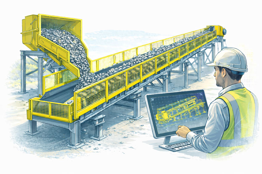

Bulk materials conveyor with compliant safety guarding at the hopper, tail end, and along the conveyor, shown with an engineer reviewing guarding design drawings.
3D LiDAR scanning and 3D modelling service button โ€” laser scanner capturing a point cloud for engineering and CAD modelling
Mechanical engineering services

What Is AS 1755?

AS 1755 is the Australian Standard that defines safety requirements for belt conveyors and other conveyor systems. It addresses both new and existing installations and applies to conveyors used in industrial, commercial, and processing environments.

Rather than focusing on individual guarding components in isolation, AS 1755 considers the conveyor system as a whole, including how people interact with it during normal operation, inspection, cleaning, and maintenance.

The standard is referenced by regulators, safety professionals, and engineers as the primary benchmark for conveyor safety in Australia.


Key Safety Principles in AS 1755

AS 1755 is built around a number of core safety principles that influence how conveyor guarding should be designed.

These include eliminating hazards where possible, controlling remaining risks through engineering solutions, and ensuring that guarding does not introduce new risks by restricting access or encouraging unsafe behaviour.

In practice, this means that compliant guarding must be effective, durable, and suitable for the operating environment, while still allowing conveyors to be inspected, cleaned, and maintained safely.


Conveyor Guarding Requirements

A major focus of AS 1755 is the control of access to hazardous areas. This includes guarding of:

  • Drive pulleys and tail pulleys
  • Return rollers and idlers
  • Nip points and shear points
  • Rotating shafts and couplings
  • Chain drives, belt drives, and gearboxes

Guarding must be designed so that body parts cannot access hazardous zones, taking into account reach distances, openings, and the position of the conveyor relative to walkways or platforms.

Importantly, AS 1755 recognises that guarding must be fit for purpose. Poorly designed guards that are difficult to remove, inspect, or maintain are often bypassed or removed altogether, creating new safety risks.


Fixed Guards vs Interlocked Guards

AS 1755 allows for different types of guarding depending on the application and risk profile.

Fixed guards are commonly used where access is not required during normal operation. These guards must be securely fixed and require tools for removal.

Interlocked guards may be required where regular access is necessary. These systems ensure that the conveyor cannot operate while the guard is open or removed, reducing the risk of exposure to moving parts.

Selecting the appropriate guarding strategy requires an understanding of how the conveyor is used in practice, not just how it appears on drawings.


Existing Conveyors and Retrofit Challenges

Many conveyors currently in service were installed before the latest versions of AS 1755 were adopted. In these cases, compliance is often achieved through retrofit guarding rather than full replacement.

Retrofitting guarding to existing conveyors introduces additional challenges, including:

  • Limited space around existing equipment
  • Incomplete or outdated drawings
  • Structural constraints
  • Ongoing operation during upgrades

Engineering-led assessment and accurate documentation of existing conditions are critical when designing retrofit guarding solutions that comply with AS 1755 without disrupting operations.


The Role of Engineering in Conveyor Guarding Design

AS 1755 does not provide prescriptive โ€œone-size-fits-allโ€ guard designs. Instead, it sets performance requirements that must be interpreted and applied by competent professionals.

Engineering input is essential to ensure that conveyor guarding:

  • Addresses all relevant hazards
  • Integrates with existing mechanical and structural systems
  • Can be fabricated and installed accurately
  • Supports safe maintenance and inspection activities

Poorly engineered guarding may appear compliant on paper but fail in real-world use.


Documentation, Verification, and Ongoing Safety

Compliance with AS 1755 is not a one-time activity. Conveyor systems evolve over time as layouts change, equipment is upgraded, and operating practices shift.

Clear documentation of guarding design, installation, and assumptions provides a baseline for future modifications and safety reviews. This documentation is also critical when demonstrating due diligence to regulators or during incident investigations.


Why AS 1755 Matters

AS 1755 exists to prevent serious injuries and fatalities associated with conveyor systems. When applied correctly, it provides a structured framework for identifying hazards, implementing effective controls, and maintaining safe operation over the life of the equipment.

Achieving compliance requires more than installing mesh around moving parts. It requires understanding how people interact with conveyors and designing guarding that supports safe behaviour rather than working against it.


Hamilton By Design logo displayed on a blue tilted rectangle with a grey gradient background

Conveyor guarding designed in accordance with AS 1755 is a critical component of safe industrial operations. Engineering-led design, accurate documentation, and practical consideration of maintenance and operation are essential to achieving compliance that works in practice.

When conveyor safety is treated as an engineering problem rather than a checkbox exercise, the result is safer equipment, fewer incidents, and more reliable operations.

Manufacturing and production services button

Our clients

Name
Would you like us to arrange a phone consultation for you?
Address

3D CAD Modelling Australia service banner for Hamilton By Design


CHPP Engineering title graphic featuring bold white text reading "CHPP Engineering" centred on a blue rounded rectangle background.
Pipework Drafting title graphic featuring bold white text reading "Pipework Drafting" centred on a blue rounded rectangle background.
3D LiDAR Scanning for Engineering Projects title graphic featuring bold white text on a blue rounded rectangle background.


Finite Element Analysis (FEA) engineering simulation button
Structural drafting services button
Mechanical drafting services button


Australian Drafting logo featuring bold white text reading "Australian Drafting" centred on a blue rounded rectangle background.
Engineering Governance title graphic featuring bold white text reading "Engineering Governance" centred on a blue rounded rectangle background.
Engineering-Grade LiDAR Scanning title graphic featuring bold white text on a blue rounded rectangle background.


Mechanical drafting services button
Structural drafting services button


Fabrication and product design services
3D CAD Modelling Australia service banner for Hamilton By Design
Mechanical, Structural & Pipework Drafting service banner by Hamilton By Design featuring white text on a blue background.


3D LiDAR scanning and 3D modelling service button โ€” laser scanner capturing a point cloud for engineering and CAD modelling
Mechanical engineering services

Mechanical Engineering | Structural Engineering


Mackayโ€™s Industrial Edge

Mackayโ€™s Industrial Edge โ€” How 3D LiDAR, Modern Engineering & Digital Modelling Supercharge Regional Projects

Located on the tropical Queensland coast but powering heavy industry, mining support and agricultural logistics, Mackay stands as a unique regional powerhouse. With its massive sugar industry, proximity to the Bowen Basin coalfields, thriving fabrication sector, marine and port operations โ€” plus a growing push toward industrial expansion โ€” the cityโ€™s infrastructure demands are both diverse and complex.

At Hamilton By Design, we recognise that projects in Mackay need more than โ€œold-schoolโ€ drawings or rough-site surveys. Thatโ€™s why we offer state-of-the-art 3D LiDAR laser scanning, comprehensive mechanical and structural engineering, advanced 3D modelling, and fabrication-ready drafting โ€” all designed to meet Mackayโ€™s rigorous industrial, mining-support and agricultural demands.

If youโ€™re planning an upgrade to a processing facility, expanding a plant or fabricating complex steelwork, our services ensure precision, efficiency and reliability from start to finish.


Why Mackay Is a Perfect Fit for Digital Engineering & 3D Scanning

Mackayโ€™s blend of industries โ€” sugar mills, mining, fabrication, marine, port logistics and heavy machinery โ€” means that most facilities are a patchwork of legacy infrastructure, ongoing modifications and high-demand production cycles.

That brings challenges like:

  • undocumented pipework, conveyors or structural changes;
  • tight tolerances for retrofits or new installations;
  • heavy mechanical equipment requiring accurate alignment and structural support;
  • short windows for shutdowns or maintenance;
  • mixed use of fabrication, mining-grade components, and agricultural processing equipment.

For these reasons, the old ways of tape-measure site surveys and manual sketches are often not enough.

Enter 3D LiDAR scanning. By capturing the entire facility geometry with millimetre-level accuracy, you get a complete digital โ€œas-builtโ€ record โ€” capturing everything from structural steel, ductwork, conveyors, foundations, and terrain, to existing equipment and utilities.

Through Hamilton By Designโ€™s professional scanning services, Mackay clients receive real-world data that supports safer, faster and more accurate project planning, design and fabrication.


From Point Cloud to Precision Design: 3D Modelling & Drafting

Once your site is scanned, our team converts the raw scan data into intelligent 3D CAD models โ€” delivering:

  • accurate mechanical and structural layouts;
  • fabrication-ready drawings (GA, detail drawings, isometrics, BOMs);
  • clash detection and interference checking before fabrication starts;
  • easy visualisation for stakeholders, clients and contractors;

  • digital archives for future modifications or maintenance.

This kind of precision work dramatically reduces risk โ€” especially for brownfield sites or mixed-use facilities common in Mackayโ€™s industrial sector.


Engineering Support Built for Mackayโ€™s Key Industries

Whether itโ€™s a sugar mill retrofit, mining support workshop, marine fabrication yard, or industrial workshop expansion โ€” the range of engineering challenges in Mackay is enormous. Hamilton By Design brings specialist mechanical and structural engineering expertise to the table, offering:

  • structural assessments (supports, platforms, load-bearing frames, foundations)
  • alignment and vibration analysis for conveyors, heavy machinery, pumps
  • design of new equipment layouts, piping, ducting and supports
  • fatigue, stress and load-bearing analysis (FEA) when needed
  • compliance-ready drawings and design documentation for local regulations and safety standards

This level of engineering support is often critical for projects involving heavy loads, mining-grade equipment, or large-scale fabrication โ€” exactly the types of projects abundant across Mackay.


3D LiDAR Laser Scanning โ€” The Game Changer for Mackay Projects

Especially when plants are being upgraded, new modules added, or older sites refurbished, accurate spatial data is the foundation for success.

Our 3D LiDAR laser scanning service ensures:

  • complete, precise capture of existing site geometry โ€” steelwork, structure, terrain, utilities;
  • minimal site downtime โ€” faster capture than manual survey;
  • safer field operations (less need for manual measurements in active plants);
  • high-fidelity base for design, modelling and fabrication;
  • better coordination between contractors, fabricators and engineers.

Learn more about our 3D LiDAR services here: https://www.hamiltonbydesign.com.au/home/3d-lidar-scanning-digital-quality-assurance/3d-laser-scanning/

For a city like Mackay โ€” with fast-paced industrial demand, tight tolerances, and high-volume production โ€” this technology isnโ€™t just beneficial, itโ€™s essential.


One Integrated Workflow: From Scan to Delivery

What sets Hamilton By Design apart is our seamless, end-to-end service:

  1. Conduct 3D LiDAR scan of the facility or site
  2. Process point-cloud data and clean up for modelling
  3. Build detailed 3D CAD models โ€” mechanical, structural, architectural
  4. Perform engineering assessments, structural/ mechanical analysis or modifications as needed
  5. Produce fabrication-ready drawings and documentation
  6. Provide digital reports, QA data and as-built records for the client

Having a single point of accountability โ€” scan, model, engineer, deliver โ€” reduces miscommunication, avoids rework and ensures that every part of the project is aligned, documented, and traceable.


Hamilton By Design logo displayed on a blue tilted rectangle with a grey gradient background
3D LiDAR scanning and 3D modelling service button โ€” laser scanner capturing a point cloud for engineering and CAD modelling
Mechanical engineering services

Why Mackay Businesses Should Use Hamilton By Design

Whether youโ€™re running a sugar mill, a fabrication workshop servicing Bowen Basin mines, a workshop for heavy equipment repairs, or a marine engineering facility servicing port exports โ€” Mackayโ€™s industrial landscape is complex.

By using cutting-edge 3D laser scanning, accurate modelling, and expert engineering, Hamilton By Design helps you:

  • save time and money on site surveys;
  • avoid costly rework from inaccurate measurements;
  • ensure tighter tolerances, safer installations and compliance;
  • speed up design, fabrication and installation;
  • maintain digital records for ongoing maintenance or future upgrades.

For industries in Mackay that deal with heavy loads, tight schedules, and high-volume production โ€” this is a competitive advantage.

Our Clients

Name
Would you like us to arrange a phone consultation for you?
Address
3D LiDAR scanning and 3D modelling service button โ€” laser scanner capturing a point cloud for engineering and CAD modelling
Mechanical engineering services
Finite Element Analysis (FEA) engineering simulation button
Mechanical engineering services
3D LiDAR scanning and 3D modelling service button โ€” laser scanner capturing a point cloud for engineering and CAD modelling
Mechanical engineering services


Finite Element Analysis (FEA) engineering simulation button
Mechanical engineering services


3D CAD Modelling Australia service banner for Hamilton By Design


CHPP Engineering title graphic featuring bold white text reading "CHPP Engineering" centred on a blue rounded rectangle background.
Pipework Drafting title graphic featuring bold white text reading "Pipework Drafting" centred on a blue rounded rectangle background.
3D LiDAR Scanning for Engineering Projects title graphic featuring bold white text on a blue rounded rectangle background.


Finite Element Analysis (FEA) engineering simulation button
Structural drafting services button
Mechanical drafting services button


Australian Drafting logo featuring bold white text reading "Australian Drafting" centred on a blue rounded rectangle background.
Engineering Governance title graphic featuring bold white text reading "Engineering Governance" centred on a blue rounded rectangle background.
Engineering-Grade LiDAR Scanning title graphic featuring bold white text on a blue rounded rectangle background.

Opinion: What Cutting 50% of Australiaโ€™s Iron Ore Exports to China Would Really Mean


By Anthony Hamilton, Mechanical Engineer and Industry Analyst


Australiaโ€™s relationship with China has always been a balancing act between economic dependence and strategic independence. Nowhere is that tension clearer than in our trade of iron ore โ€” the mineral that built both our national budget and Chinaโ€™s skyline.

Imagine, then, a bold decision: Australia deliberately cuts its iron ore exports to China by half and pivots toward domestic manufacturing โ€” especially green steel and renewable-powered industry. What would that mean for our economy, our global influence, and our future as an industrial nation?

The answer is both disruptive and transformative.


The Shock: Short-Term Pain

Letโ€™s be clear: halving iron ore exports would jolt the economy.

Australia exported about 900 million tonnes of iron ore in 2024โ€“25, worth roughly A$160 billion, with China buying four-fifths of it. Slashing that volume by half would pull A$80โ€“90 billion out of export revenue almost overnight. Even if prices spiked 50% amid global shortages, our GDP would still take a hit of 2โ€“3% in the first years โ€” a deliberate, self-imposed economic slowdown.

Western Australia, which lives and breathes the ore trade, would feel it most: reduced royalties, idle capacity, and strained state budgets. Canberraโ€™s tax intake could drop by A$10โ€“15 billion per year in the early phase.

But these are short-term tremors โ€” not structural decline. The question is whether we can replace raw-ore exports with something better: value-added industrial activity on Australian soil.


The Transition: Turning Rocks into Revenue

If half of that diverted ore were converted into green steel, the economic story changes dramatically.
One tonne of steel is worth four to six times more than the same tonne of ore. Even modest domestic processing could create an A$100 billion green industry within a decade โ€” generating thousands of high-skill jobs across hydrogen, renewables, materials science, and engineering.

Projects in Whyalla, Gladstone, and the Pilbara already point the way. With the right investment โ€” perhaps A$60โ€“100 billion over ten years โ€” Australia could build the capacity to supply its own construction, defence, and transport sectors while exporting carbon-neutral steel to the world.

Thatโ€™s not deglobalisation. Itโ€™s smart industrialisation โ€” keeping the value chain at home instead of shipping our competitive advantage overseas.


The Payoff: Long-Term Strength

By 2035, the payoff could be substantial:

  • GDP grows larger and more balanced, driven by advanced manufacturing.
  • Australia becomes a reliable producer of green steel, battery materials, and hydrogen infrastructure.
  • Dependence on Chinese demand declines, while new trade with India, Japan, Korea, and Europe expands.

In this scenario, Australiaโ€™s GDP could be 2โ€“4% higher than the business-as-usual case โ€” smaller mining exports, but far greater industrial depth. Itโ€™s a shift from volume to value, from being the worldโ€™s quarry to being part of its workshop again.


The Risk: A Test of Political Will

Such a move isnโ€™t without risk. China would almost certainly retaliate โ€” delaying other imports, applying political pressure, and exploiting our internal divisions.
The mining lobby would fight hard to protect its margins. Politicians would face the same question every reformer does: why risk the comfortable present for an uncertain future?

Yet the uncomfortable truth is that comfort has bred complacency.
Australiaโ€™s prosperity is overly reliant on shipping low-value resources to one buyer. Thatโ€™s not economic freedom โ€” its dependency dressed as success.


The Opportunity: Building the Next Holden Moment

Half a century ago, Holden symbolised a confident, self-sufficient industrial Australia. Its closure marked the end of that era.
A green-steel renaissance could be the new Holden moment โ€” a chance to reconnect engineering, manufacturing, and national purpose. It would anchor new jobs, restore industrial pride, and ensure that Australia competes not on cost, but on competence.

Weโ€™d still dig things up โ€” but weโ€™d also make things again.


Conclusion: A Strategic Rebalance, Not an Economic Gamble

Cutting 50% of iron ore exports to China would be a strategic recalibration, not an act of economic self-harm. It would cost us in the short run, but it could redefine us in the long run โ€” from a resource economy to a resilient, innovation-driven nation.

For decades, Australiaโ€™s industrial conversation has ended with one refrain: โ€œWe canโ€™t afford to make things anymore.โ€
Perhaps the truth is the opposite.

We canโ€™t afford not to.


Mechanical Engineering | Structural Engineering

3D Scanning Sydney banner promoting engineering-grade 3D laser scanning, LiDAR scanning, and reality capture services by Hamilton By Design.
Mechanical Engineering Sydney banner with white text on a blue background representing Hamilton By Design's mechanical engineering services in Sydney.
Mechanical Drafting and 3D Modelling Sydney banner highlighting Hamilton By Design's CAD drafting, 3D modelling, and engineering design services in Sydney.

Mechanical Drafting | Structural Drafting

3D CAD Modelling | 3D Scanning

Chute Design

SolidWorks Contractors in Australia

Hamilton By Design โ€“ Blog

Custom Designed – Shipping Containers

Coal Chute Design

Mechanical Engineers in Sydney

3D LiDAR scanning and 3D modelling service button โ€” laser scanner capturing a point cloud for engineering and CAD modelling
Mechanical engineering services


Finite Element Analysis (FEA) engineering simulation button
Mechanical engineering services


3D CAD Modelling Australia service banner for Hamilton By Design


CHPP Engineering title graphic featuring bold white text reading "CHPP Engineering" centred on a blue rounded rectangle background.
Pipework Drafting title graphic featuring bold white text reading "Pipework Drafting" centred on a blue rounded rectangle background.
3D LiDAR Scanning for Engineering Projects title graphic featuring bold white text on a blue rounded rectangle background.


Finite Element Analysis (FEA) engineering simulation button
Structural drafting services button
Mechanical drafting services button


Australian Drafting logo featuring bold white text reading "Australian Drafting" centred on a blue rounded rectangle background.
Engineering Governance title graphic featuring bold white text reading "Engineering Governance" centred on a blue rounded rectangle background.
Engineering-Grade LiDAR Scanning title graphic featuring bold white text on a blue rounded rectangle background.


3D Scanning Sydney banner promoting engineering-grade 3D laser scanning, LiDAR scanning, and reality capture services by Hamilton By Design.
Mechanical Engineering Sydney banner with white text on a blue background representing Hamilton By Design's mechanical engineering services in Sydney.
Mechanical Drafting and 3D Modelling Sydney banner highlighting Hamilton By Design's CAD drafting, 3D modelling, and engineering design services in Sydney.

Mechanical Engineering | Structural Engineering


Coal Chute Design

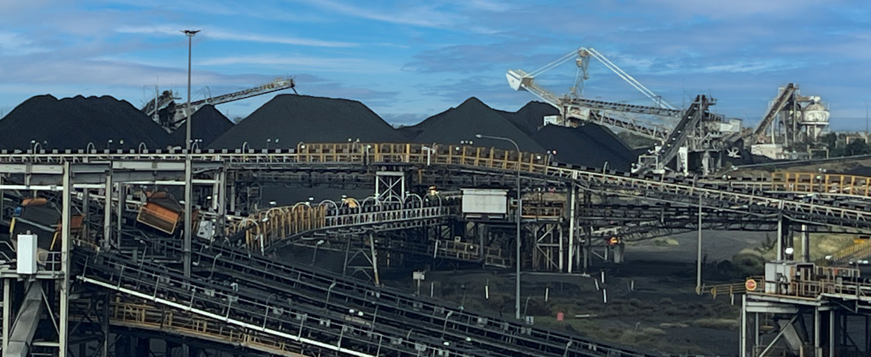
Coal handling and processing facility with multiple conveyors, stockpiles of coal, and stacking-reclaiming machinery operating under a blue sky

A Systems Engineering Approach for Reliable Coal Handling

In coal mining operations, transfer chutes play a deceptively small role with disproportionately large impacts. They sit quietly between conveyors, crushers, and stockpiles, directing tonnes of coal every hour. Yet when a chute is poorly designed or not maintained, the whole coal handling system suffers: blockages stop production, dust creates safety and environmental hazards, and worn liners demand costly maintenance shutdowns.

At Hamilton by Design, we believe coal chute design should be treated not as a piece of steelwork, but as a systems engineering challenge. By applying systems thinking, we connect stakeholder requirements, material behaviour, environmental factors, and lifecycle performance into a holistic design approach that delivers long-term value for mining operations in the Hunter Valley and beyond.


Coal Chutes in the Mining Value Chain

Coal chutes form the links in a chain of bulk material handling equipment:

  • ROM bins and crushers feed coal into the system.
  • Conveyors carry coal across site, often over long distances.
  • Transfer chutes guide coal between conveyors or onto stockpiles.
  • Load-out stations deliver coal to trains or ports for export.

Although they are small compared to conveyors or crushers, coal chutes are often where problems first appear. A well-designed chute keeps coal flowing consistently; a poorly designed one causes buildup, spillage, dust emissions, and accelerated wear. Thatโ€™s why leading operators now see chute design as a critical system integration problem rather than just a fabrication task.

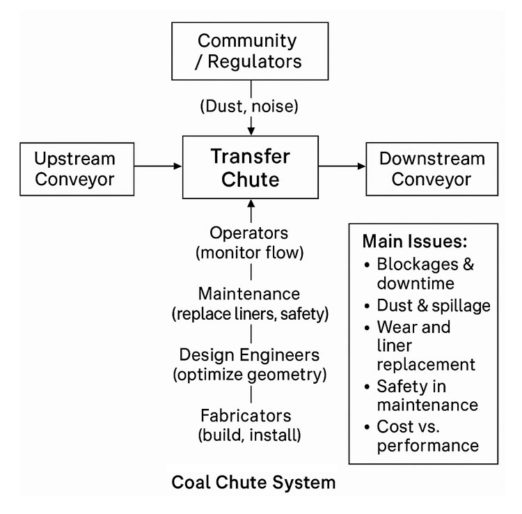
Flow diagram of a coal chute system showing upstream and downstream conveyors, the transfer chute, stakeholder interactions, and main issues such as blockages, dust, wear, maintenance safety, and cost versus performance

Systems Engineering in Coal Chute Design

Systems engineering is the discipline of managing complexity in engineering projects. It recognises that every component is part of a bigger system, with interdependencies and trade-offs. Applying this mindset to coal chute design ensures that each chute is considered not in isolation, but as part of the broader coal handling plant.

1. Requirements Analysis

The first step is gathering and analysing stakeholder and system requirements:

  • Throughput capacity: e.g. handling 4,000 tonnes per hour of coal.
  • Material properties: coal size distribution, moisture content, abrasiveness, stickiness.
  • Safety requirements: compliance with AS/NZS 4024 conveyor safety standards, confined space entry protocols, guarding, and interlocks.
  • Environmental compliance: dust, noise, and spillage limits.
  • Maintenance objectives: target liner life (e.g. 6 months), maximum downtime per liner change (e.g. 30 minutes with two workers).

A structured requirements phase reduces the risk of costly redesign later in the project.

2. System Design and Integration

Once requirements are defined, the design process considers how the chute integrates into the coal handling system:
  • Flow optimisation using DEM: Discrete Element Modelling allows engineers to simulate coal particle behaviour, test different geometries, and reduce blockages before steel is ever cut.
  • Dust control strategies: designing chutes with enclosures, sprays, and extraction ports to minimise airborne dust.
  • Wear management: predicting wear zones, selecting suitable liner materials (ceramic, Bisplate, rubber composites), and ensuring easy access for replacement.
  • Structural and safety design: ensuring the chute can withstand dynamic loads, vibration, and impact, while providing safe access platforms and guarding.
  • Interfaces with conveyors and crushers: alignment, skirt seals, trip circuits, and integration with PLC/SCADA control systems.

By treating the chute as a subsystem with multiple interfaces, designers avoid the โ€œbolt-onโ€ mentality that often leads to operational headaches.


3. Verification and Validation

The systems engineering V-model reminds us that every requirement must be verified and validated:

  • Component verification: weld inspections, liner hardness testing, nozzle spray checks.
  • Subsystem verification: chute section fit-up, guard gap measurements, coating checks.
  • Integration testing: conveyor-chute alignment, PLC spray interlocks, trip circuits.
  • System validation: commissioning with live coal flow, dust monitoring against limits, maintainability time trials for liner change.

By linking requirements directly to tests in a traceability matrix, operators can be confident that the chute is not only built to spec, but proven in operation.


Lifecycle Engineering: Beyond Installation

Good chute design doesnโ€™t stop at commissioning. A lifecycle engineering mindset ensures the chute continues to deliver performance over years of operation.

  • Maintainability: modular liners, captive fasteners, hinged access doors, and clear procedures reduce downtime and improve worker safety.
  • Reliability: DEM-informed designs and wear-resistant materials reduce the frequency of blockages and rebuilds.
  • Sustainability: dust suppression and enclosure strategies reduce environmental impact and support community and regulatory compliance.
  • Continuous improvement: feedback loops from operators and maintenance teams feed into the next design iteration, closing the systems engineering cycle.

A Rich Picture of Coal Chute Complexity

Visualising the coal chute system as a rich picture reveals its complexity:

  • Operators monitoring flow from control rooms.
  • Maintenance crews working in confined spaces, replacing liners.
  • Design engineers using DEM simulations to model coal flow.
  • Fabricators welding heavy plate sections on site.
  • Environmental officers measuring dust levels near transfer points.
  • Regulators and community monitoring compliance.

This web of relationships shows why coal chute design benefits from systems thinking. No single stakeholder sees the whole pictureโ€”but systems engineering does.


Benefits of a Systems Engineering Approach

When coal chute design is guided by systems engineering principles, operators gain:

  • Higher reliability: smoother coal flow with fewer blockages.
  • Lower maintenance costs: liners that last longer and can be swapped quickly.
  • Improved compliance: dust, spillage, and safety issues designed out, not patched later.
  • Lifecycle value: less unplanned downtime and a lower total cost of ownership.

In short, systems engineering transforms coal chutes from weak links into strong connectors in the mining value chain.


Case Study: Hunter Valley Context

In the Hunter Valley, coal mines have long struggled with transfer chute problems. Companies like T.W. Woods, Chute Technology, HIC Services, and TUNRA Bulk Solids have all demonstrated the value of combining local fabrication expertise with advanced design tools. Hamilton by Design builds on this ecosystem by applying structured systems engineering methods, ensuring each chute project balances performance, safety, cost, and sustainability.


Conclusion

Coal chute design might seem like a small detail, but in mining, details matter. When transfer chutes fail, production stops. By applying systems engineering principlesโ€”from requirements analysis and DEM modelling to verification, lifecycle planning, and continuous improvementโ€”we can design coal chutes that are reliable, maintainable, and compliant.

At Hamilton by Design, we believe in tackling these challenges with a systems mindset, delivering solutions that stand up to the realities of coal mining.


Are you struggling with coal chute blockages, dust, or costly downtime in your coal handling system?

Hamilton By Design logo displayed on a blue tilted rectangle with a grey gradient background

Contact Hamilton by Design today and discover how our systems engineering expertise in coal chute design can optimise your mining operations for performance, safety, and sustainability.

Mechanical Engineering | Structural Engineering

Mechanical Drafting | Structural Drafting

3D CAD Modelling | 3D Scanning

Chute Design

SolidWorks Contractors in Australia

Hamilton By Design โ€“ Blog

Our clients:

Name
Would you like us to arrange a phone consultation for you?
Address
Finite Element Analysis (FEA) engineering simulation button
Mechanical engineering services

Engineering Integrity, Failure Evolution, and Energy Transition: A Mechanical Engineerโ€™s Perspective on Australiaโ€™s Ageing Coal Fleet

This paper examines the mechanical degradation, failure mechanisms, and system-level reliability implications of Australiaโ€™s ageing coal-fired power generation assets, focusing on Callide Power Station (Queensland) and Yallourn Power Station (Victoria). Both stations have experienced significant mechanical failures in the past five years, exposing vulnerabilities in maintenance, asset management, and risk governance under conditions of declining reinvestment.
From a mechanical engineering standpoint, these failures illustrate the predictable end-of-life behaviour of large rotating and pressure-bound systems when maintenance expenditure, material renewal, and operational monitoring decline. The paper argues that sustained industrial reliabilityโ€”and thus national energy and employment securityโ€”requires engineering-informed policy that balances decarbonisation with technical integrity management.


Coal-fired power stations are among the most complex mechanical systems ever built in Australia. They integrate high-temperature, high-pressure thermodynamic processes with massive rotating equipment, lubrication systems, and precision alignment tolerances.

From a mechanical engineerโ€™s perspective, their reliability depends on three interlinked pillars:

  1. Structural and material integrity,
  2. Lubrication and vibration control, and
  3. Predictive maintenance and monitoring.

However, as the nation accelerates toward renewable transition targets, investment in these legacy systems has declined. Mechanical failures at Callide and Yallourn are therefore not random accidents but the mechanical manifestation of economic and policy choices.

This analysis seeks to understand those failures in engineering terms, predict future risks, and outline how a re-commitment to industrial infrastructure and jobs requires a concurrent commitment to mechanical reliability.


Technical Overview of Recent Failures

Callide Power Station

Callideโ€™s units span several generations of design and material technology. The C4 explosion (2021) was catastrophic: the failure originated within the turbine hall, leading to structural collapse and large-scale ejection of debris.
Subsequent analysis by CS Energy and external investigators identified battery charger replacement errors, inadequate isolation protocols, and loss of process safety discipline as initiators.

From an engineering integrity perspective, the incident represents a compound failure:

  • Mechanical systems operated under degraded conditions;
  • Electrical and process-control systems failed to detect early anomalies;
  • Organisational maintenance controls were insufficient to interrupt escalation.

Later failures โ€” including the C3 boiler pressure event (2025) and cooling tower collapse (2022) โ€” further confirm that structural materials, corrosion protection, and load-carrying assemblies had entered the fatigueโ€“creep interaction phase of their service life.

Yallourn Power Station

At Yallourn, the August 2025 low-pressure turbine dislodgement occurred after decades of vibration monitoring alarms and bearing wear signals. Earlier (2024) shutdowns for โ€œhigh vibration alarmsโ€ indicated growing rotor dynamic instability.
When the Unit 2 turbine dislodged, the damage pattern suggested bearing wear, misalignment, or bolt relaxation leading to component displacement.

In mechanical engineering terms, this is a classic late-life failure sequence:

  1. Fatigue crack initiation in critical load-carrying components (rotor or coupling bolts),
  2. Progressive loosening and unbalance,
  3. Dynamic amplification under operating RPM,
  4. Catastrophic structural displacement.

The turbineโ€™s dislodgement was therefore an expected end-of-life event, accelerated by reduced overhaul investment and ageing metallurgical properties.


Comparative Engineering Analysis

Engineering DimensionCallideYallournComparison / Insight
Failure TypeExplosion / Pressure Containment BreachTurbine Mechanical DislodgementCallide shows energy-release failure; Yallourn a structural integrity loss.
Root Mechanical CauseOverpressure / process safetyFatigue, unbalance, bearing or bolt failureBoth reflect cumulative degradation.
Indicative Material StateCreep-fatigued pressure shells; corroded supportsThermal-fatigued steel, worn journalsMetallurgical ageing dominates both.
Maintenance CultureProcess-safety erosionReactive, โ€œrun-to-retirementโ€Organisational degradation common factor.
System OutcomeExplosion and total destructionSevere mechanical damage, unit outageBoth reduce grid reliability and reveal systemic neglect.

These failures share a unifying pattern recognised in mechanical reliability theory:

Late-life degradation compounded by maintenance deferral and organisational fatigue produces cascading mechanical failure modes that were once preventable.


Predicting Future Failure Behaviour

Mechanical engineers use reliability-centred maintenance (RCM) models to quantify end-of-life risk.
For rotating equipment, mean time to failure (MTTF) typically decreases exponentially once fatigue propagation exceeds ~70 % of material endurance life.

Data from the National Electricity Market (NEM) indicates:

  • Forced outage frequency has doubled since 2012.
  • Vibration and lubrication alarms are rising in frequency.
  • Unit unavailability correlates strongly (Rยฒ > 0.8) with turbine age and last major overhaul date.

Projected forward, these indicators imply that without major overhauls or component replacements, most Australian coal units will face critical mechanical reliability decline by 2032โ€“2035.


Engineering Economics and Policy Interaction

From an engineering management perspective, the problem is not purely technical โ€” it is thermo-economic.

  • A major turbine retrofit (~A$25โ€“40 million per unit) is uneconomic for plants scheduled for closure in under a decade.
  • Operators thus defer maintenance, accepting rising mechanical risk.
  • The probability of catastrophic failure increases sharply as the cost of prevention declines below the cost of repair.

This is the engineering expression of policy-induced obsolescence: political commitments to retire coal reduce the incentive to sustain its mechanical integrity, even while industries still depend on its output.


Industrial Reliability and the Employment Interface

Reliable baseload power is the foundation for industrial continuity.
From the standpoint of a mechanical engineer, industrial productivity is a function of mechanical uptime: Productivity=f(Power Reliability,Maintenance Efficiency)\text{Productivity} = f(\text{Power Reliability}, \text{Maintenance Efficiency})Productivity=f(Power Reliability,Maintenance Efficiency)

When power generation becomes intermittentโ€”whether from renewable intermittency or coal unreliabilityโ€”industrial operations must compensate with redundancy, backup generation, or load-shedding. These add capital and operational costs that ultimately affect employment.

Regional Implications

  • Queensland retains a stronger firm power horizon (coal + gas + hydro until ~2035), giving industry more operational certainty.
  • Victoria, by contrast, will face a reliability inflection point after Yallourn (2028) and Loy Yang A (2035) closures.

Without firm generation or large-scale storage online, manufacturing regions risk power volatilityโ€”directly translating to production downtime and job insecurity.


Engineering the Transition: Commitment to Jobs and Infrastructure

From a mechanical engineering ethics and systems standpoint, a commitment to industry must be synonymous with a commitment to mechanical reliability.
That requires three converging actions:

Asset Integrity Management:
Continuous structural health monitoring, vibration analysis, and overhaul planning for remaining thermal units.
Even in decline, they must be safely and predictably retired.

Design and Commissioning of Replacement Systems:
Engineers must ensure that renewable generation, storage, and transmission assets meet equivalent reliability and maintainability standards.
This includes redundancy design, grid inertia replacement, and mechanical resilience of large rotating machinery (e.g., pumped hydro, turbines, bearings).

Workforce Transition as Engineering Continuity:
The skills used to maintain turbines, bearings, and boilers are transferable to wind, hydro, and hydrogen equipment.
Protecting those jobs preserves both mechanical capability and national energy security.


Engineering Conclusions

From a mechanical engineerโ€™s viewpoint, the failures at Callide and Yallourn are textbook case studies of end-of-life degradation under policy-driven neglect.
They illustrate that:

  1. Mechanical degradation is predictable โ€” vibration, lubrication, and thermal-stress indicators were present years before failure.
  2. Organisational and policy decisions override engineering recommendations โ€” maintenance deferral was economic, not technical.
  3. Systemic reliability cannot be sustained without mechanical investment โ€” whether in turbines, batteries, or hydro equipment, engineering integrity remains central.
  4. A national commitment to industry equals a commitment to engineering.

If Australia seeks to safeguard its industrial base and employment, it must invest not only in new energy technologies but in the mechanical soundness of the systems that bridge the transition.
Neglecting this will reproduce the same failure patternsโ€”just in new forms of infrastructure.


References (Indicative)

  • CS Energy (2024). Callide C4 Incident Investigation Summary.
  • WattClarity (2025). Analysis of Yallourn Unit 2 Trip and Frequency Response.
  • AEMO (2025). Generator Reliability Performance Report.
  • EnergyAustralia (2025). Yallourn Mechanical Maintenance Overview.
  • IEEFA (2025). Delaying Coal Power Exits: Engineering and Economic Implications.
  • ASME (2023). Guidelines on Turbine Rotor Life Assessment and Remaining Life Prediction.
3D LiDAR scanning and 3D modelling service button โ€” laser scanner capturing a point cloud for engineering and CAD modelling
Mechanical engineering services


Finite Element Analysis (FEA) engineering simulation button
Mechanical engineering services


3D CAD Modelling Australia service banner for Hamilton By Design


CHPP Engineering title graphic featuring bold white text reading "CHPP Engineering" centred on a blue rounded rectangle background.
Pipework Drafting title graphic featuring bold white text reading "Pipework Drafting" centred on a blue rounded rectangle background.
3D LiDAR Scanning for Engineering Projects title graphic featuring bold white text on a blue rounded rectangle background.


Finite Element Analysis (FEA) engineering simulation button
Structural drafting services button
Mechanical drafting services button


Australian Drafting logo featuring bold white text reading "Australian Drafting" centred on a blue rounded rectangle background.
Engineering Governance title graphic featuring bold white text reading "Engineering Governance" centred on a blue rounded rectangle background.
Engineering-Grade LiDAR Scanning title graphic featuring bold white text on a blue rounded rectangle background.

Chute Design in the Mining Industry

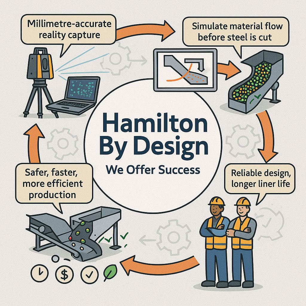
Infographic showing Hamilton By Designโ€™s engineering workflow, including millimetre-accurate LiDAR reality capture, material-flow simulation, optimised chute designs, and safer, more efficient production outcomes. Two workers in PPE highlight reliable design and longer liner life, with icons representing time, cost and quality benefits.

Getting Coal, Hard Rock, and ROM Material Flow Right

Chute design is one of the most critical yet challenging aspects of mining and mineral processing. Whether you are handling coal, hard rock ore, or raw ROM material, chutes and transfer stations are the unsung workhorses of every operation. When designed well, they guide material smoothly, minimise wear, and keep conveyors running. When designed poorly, they cause blockages, spillage, excessive dust, and expensive downtime.

Modern chute design has moved far beyond rules of thumb and back-of-the-envelope sketches. Today, successful projects rely on accurate as-built data, particle trajectory analysis, and advanced Discrete Element Method (DEM) simulation to predict, visualise, and optimise material flow before steel is cut. In this article, we explore why these tools have become essential, how they work together, and where software can โ€” and cannot โ€” replace engineering judgement.


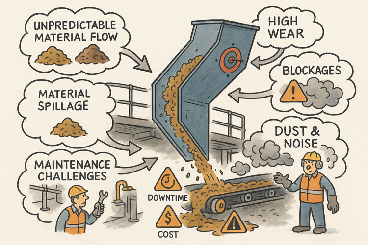
Illustration showing common problems with poorly designed material-handling chutes. A chute discharges material onto a conveyor while issues are highlighted around it: unpredictable material flow, material spillage, maintenance challenges, high wear, blockages, and dust and noise. Warning icons for downtime and cost appear on the conveyor, and workers are shown dealing with the resulting hazards and maintenance tasks.

The Challenge of Chute Design

Coal and hard rock have very different flow behaviours. Coal tends to be softer, generate more dust, and be prone to degradation, while hard rock is more abrasive and can damage chutes if impact angles are not controlled. ROM material adds another level of complexity โ€” oversize lumps, fines, and moisture variation can cause hang-ups or uneven flow.

Chute design must balance several competing objectives:

  • Control the trajectory of incoming material to reduce impact and wear
  • Prevent blockages by maintaining flowability, even with wet or sticky ore
  • Manage dust and noise to meet environmental and workplace health requirements
  • Fit within existing plant space with minimal modification to conveyors and structures
  • Be maintainable โ€” liners must be accessible and replaceable without excessive downtime

Meeting all these goals without accurate data and simulation is like trying to design in the dark.


Illustrated graphic showing a tripod-mounted 3D laser scanner capturing millimetre-accurate as-built data in an industrial plant with conveyors and walkways. Speech bubbles highlight issues such as โ€œOutdated drawings donโ€™t tell the full storyโ€ and โ€œModifications rarely get documented.โ€ The scan data is shown being visualised on a laptop, with notes describing full coverage of conveyors, walkways, and services. Benefits listed along the bottom include faster data collection, fewer site revisits, safer shutdowns, accurate starting point for design simulation, and safer outcomes that ensure designs fit first time.

Capturing the Truth with 3D Scanning

The first step in any successful chute project is to understand the as-built environment. In many operations, drawings are outdated, modifications have been made over the years, and the real plant geometry may differ from what is on paper. Manual measurement is slow, risky, and often incomplete.

This is where 3D laser scanning changes the game. Using tripod-mounted or mobile LiDAR scanners, engineers can capture the entire transfer station, conveyors, surrounding steelwork, and services in a matter of hours. The result is a dense point cloud with millimetre accuracy that reflects the true state of the plant.

From here, the point cloud is cleaned and converted into a 3D model. This ensures the new chute design will not clash with existing structures, and that all clearances are known. It also allows maintenance teams to plan safe access for liner change-outs and other work, as the scanned model can be navigated virtually to check reach and access envelopes.


Understanding Particle Trajectory

Once the physical environment is known, the next challenge is to understand the particle trajectory โ€” the path that material takes as it leaves the head pulley or previous transfer point.

Trajectory depends on belt speed, material characteristics, and discharge angle. For coal, fine particles may spread wider than the coarse fraction, while for ROM ore, large lumps may follow a ballistic path that needs to be controlled to prevent impact damage.

Accurately modelling trajectory ensures that the material enters the chute in the right location and direction. This minimises impact forces, reducing wear on liners and avoiding the โ€œsplashโ€ that creates spillage and dust. It also prevents the material from hitting obstructions or dead zones that could lead to build-up and blockages.

Modern software can plot the trajectory curve for different loading conditions, providing a starting point for chute geometry. This is a critical step โ€” if the trajectory is wrong, the chute design will be fighting against the natural path of the material.


The Power of DEM Simulation

While trajectory gives a first approximation, real-world flow is far more complex. This is where Discrete Element Method (DEM) simulation comes into play. DEM models represent bulk material as thousands (or millions) of individual particles, each following the laws of motion and interacting with one another.

When a DEM simulation is run on a chute design:

  • You can visualise material flow in 3D, watching how particles accelerate, collide, and settle
  • Impact zones become clear, showing where liners will wear fastest
  • Areas of turbulence, dust generation, or segregation are identified
  • Build-up points and potential blockages are predicted

This allows engineers to experiment with chute geometry before fabrication. Angles can be changed, ledges removed, and flow-aiding features like hood and spoon profiles or rock-boxes optimised to achieve smooth, controlled flow.

For coal, DEM can help ensure material lands gently on the receiving belt, reducing degradation and dust. For hard rock, it can ensure that the energy of impact is directed onto replaceable wear liners rather than structural plate. For ROM ore, it can help prevent oversize lumps from wedging in critical locations.


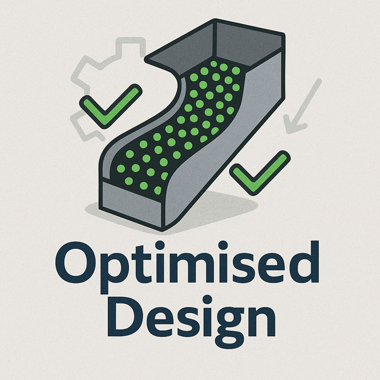
Illustration of an optimised chute design showing material flow represented by green particles, with check marks and gear icons indicating improved efficiency and engineered performance.

๐Ÿ–ฅ Strengths and Limitations of Software

Modern DEM packages are powerful, but they are not magic. Software such as EDEM, Rocky DEM, or Altairโ€™s tools can simulate a wide range of materials and geometries, but they rely on good input data and skilled interpretation.

Key strengths include:

  • Ability to model complex, 3D geometries and particle interactions
  • High visualisation power for communicating designs to stakeholders
  • Capability to run multiple scenarios (different feed rates, moisture contents, ore types) quickly

However, there are limitations:

  • Material calibration is critical. If the particle shape, friction, and cohesion parameters are wrong, the results will not match reality.
  • Computational cost can be high โ€” detailed simulations of large chutes with millions of particles may take hours or days to run.
  • Engineering judgement is still needed. Software will not tell you the โ€œbestโ€ design โ€” it will only show how a proposed design behaves under given conditions.

Thatโ€™s why DEM is best used as part of a holistic workflow that includes field data, trajectory analysis, and experienced design review.


From Model to Real-World Results

When the simulation results are validated and optimised, the design can be finalised. The point cloud model ensures the chute will fit in the available space, and the DEM results give confidence that it will perform as intended.

This means fabrication can proceed with fewer changes and less risk. During shutdown, installation goes smoothly, because clashes have already been resolved in the digital model. Once commissioned, the chute delivers predictable flow, less spillage, and longer liner life.


Why It Matters More Than Ever

Todayโ€™s mining operations face tighter production schedules, stricter environmental compliance, and increasing cost pressures. Downtime is expensive, and the margin for error is shrinking.

By combining 3D scanning, trajectory modelling, and DEM simulation, operations can move from reactive problem-solving to proactive improvement. Instead of waiting for blockages or failures, they can design out the problems before they occur, saving both time and money.


Partnering for Success

At Hamilton by Design, we specialise in turning raw site data into actionable insights. Our team uses advanced 3D scanning to capture your transfer stations with precision, builds accurate point clouds and CAD models, and runs calibrated DEM simulations to ensure your new chute design performs from day one.

Whether youโ€™re working with coal, hard rock, or ROM ore, we help you deliver designs that fit first time, reduce maintenance headaches, and keep production running.

Contact us today to see how our integrated scanning and simulation workflow can make your next chute project safer, faster, and more reliable.

Mechanical Engineering | Structural Engineering

Mechanical Drafting | Structural Drafting

3D Laser Scanning | 3D CAD Modelling | 3D Scanning

Chute Design

SolidWorks Contractors in Australia

Hamilton By Design โ€“ Blog

Consulting Engineers

About Us โ€“ Hamilton By Design

Hamilton By Design | 3D Scanning | Sydney | Perth | Brisbane | Mount Isa | Lidar Scanning

Contact us

https://www.hamiltonbydesign.com.au/perth-wa
3D CAD Modelling Australia service banner for Hamilton By Design
3D LiDAR scanning and 3D modelling service button โ€” laser scanner capturing a point cloud for engineering and CAD modelling
Mechanical engineering services
3D CAD Modelling Australia service banner for Hamilton By Design
Mechanical, Structural & Pipework Drafting service banner by Hamilton By Design featuring white text on a blue background.
Australian Drafting logo featuring bold white text reading "Australian Drafting" centred on a blue rounded rectangle background.
Blue banner graphic displaying the text "Point Cloud to CAD - Australia" in large white lettering, representing point cloud processing, scan-to-CAD conversion and digital engineering services across Australia.
CHPP Engineering title graphic featuring bold white text reading "CHPP Engineering" centred on a blue rounded rectangle background.
Engineering Governance title graphic featuring bold white text reading "Engineering Governance" centred on a blue rounded rectangle background.
Mechanical engineering services
Australian Drafting logo featuring bold white text reading "Australian Drafting" centred on a blue rounded rectangle background.
3D LiDAR Scanning Hunter & Newcastle banner with white text on a blue background promoting engineering-grade laser scanning services for industrial, mining and infrastructure projects across the Hunter Valley and Newcastle region.
Mechanical Engineering Hunter & Newcastle banner promoting mechanical engineering services for mining, industrial plants, power generation, manufacturing and heavy industry throughout the Hunter Valley and Newcastle region.
Structural Drafting Hunter & Newcastle banner promoting structural drafting services for mining, industrial plants, power generation, manufacturing and infrastructure projects across the Hunter Valley and Newcastle region.
Mechanical Engineering Perth WA banner for Hamilton By Design featuring white text on a blue background.
3D Laser Scanning Perth WA banner for Hamilton By Design with white text on a blue background.
SolidWorks Perth WA banner for Hamilton By Design featuring white text on a blue background.
Fabrication and product design services
Finite Element Analysis (FEA) engineering simulation button
3D LiDAR scanning and 3D modelling service button โ€” laser scanner capturing a point cloud for engineering and CAD modelling
Blue rounded button with the text โ€œSolidWorks Designโ€ in white.
Mechanical drafting services button
Structural drafting services button

3D Scanning Sydney banner promoting engineering-grade 3D laser scanning, LiDAR scanning, and reality capture services by Hamilton By Design.
Mechanical Engineering Sydney banner with white text on a blue background representing Hamilton By Design's mechanical engineering services in Sydney.
Mechanical Drafting and 3D Modelling Sydney banner highlighting Hamilton By Design's CAD drafting, 3D modelling, and engineering design services in Sydney.

Mechanical Engineering | Structural Engineering