

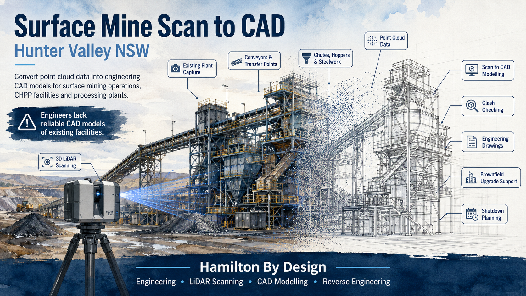
Convert Point Cloud Data into Engineering CAD Models for Surface Mining Operations and Processing Plants

Engineers working in surface mining operations across the Hunter Valley are often expected to design upgrades, replacement parts, access structures, chute modifications, conveyor changes and plant improvements without a reliable CAD model of the existing facility. In many cases, the drawings available to the project team are outdated, incomplete, unavailable from the OEM, or no longer match the real site.
That creates a serious problem.
When engineers do not have accurate CAD models of existing plant, every brownfield project begins with uncertainty. A chute may look correct on an old drawing but be different on site. A conveyor support may have been modified during a shutdown. A platform may have been extended. Pipework may have been rerouted. Guards, stairs, handrails, access points and maintenance clearances may no longer match the original design.
For surface mining and processing plant environments, this is where Surface Mine Scan to CAD becomes valuable.
Hamilton By Design supports Hunter Valley mining and industrial operations by converting 3D laser scan and LiDAR point cloud data into practical engineering CAD models. These models help engineers, maintenance teams, shutdown planners and fabricators work from the real condition of the site instead of relying on assumptions.
For broader mining-related engineering support, Hamilton By Design also provides Hunter Valley Mining Engineering & 3D Laser Scanning Services for brownfield plant, CHPP facilities, conveyor infrastructure, structural steelwork and heavy industrial assets.
The Problem: Engineers Lack Reliable CAD Models of Existing Facilities
The biggest issue in many surface mining operations is not always the lack of engineering skill. It is the lack of reliable existing information.
Engineering teams may be highly capable, but if the base model is wrong, the new design can be wrong before it starts. This is a common challenge in brownfield mining environments where plant has been modified, repaired, patched, upgraded and maintained over many years.
Old drawings are often treated as the starting point for a project, but they may not show what is actually installed. In some cases, the OEM will not provide the drawings. In other cases, the equipment has been altered so many times that the original drawing is no longer useful. The plant may have had structural modifications, replacement components, temporary repairs, maintenance improvements or shutdown changes that were never captured in CAD.
This creates risk for:
- Project engineers
- Mechanical engineers
- Structural engineers
- Drafting teams
- Maintenance planners
- Shutdown planners
- Fabricators
- Installation contractors
- Asset owners
- CHPP and processing plant managers
The result is often the same: more site measuring, more assumptions, more rework and more pressure during installation.
What Is Surface Mine Scan to CAD?
Surface Mine Scan to CAD is the process of capturing existing mining infrastructure using 3D laser scanning or LiDAR, then converting the point cloud into usable engineering CAD models.
A point cloud is a highly detailed digital capture of the physical environment. It records the real position and shape of steelwork, conveyors, platforms, chutes, hoppers, bins, tanks, pumps, pipework, handrails, access stairs, guarding and surrounding plant.
However, a point cloud by itself is not always enough.
Engineers usually need the scan data converted into a CAD format they can use for design, checking, fabrication or installation planning. That may include SolidWorks models, Inventor models, AutoCAD drawings, Navisworks coordination files, STEP files, SAT files, DWG files, DXF files, general arrangement drawings, sections, elevations or fabrication drawings.
The value is not just the scan. The value is turning the scan into engineering information.
Hamilton By Design’s 3D CAD Modelling Australia service supports this exact problem by creating practical 3D models from point clouds, existing drawings, PDFs, sketches, marked-up plans and site measurements.
Why Surface Mining Operations Need Scan to CAD
Surface mining operations are full of existing assets that are difficult to measure accurately by hand. These facilities often include conveyors, transfer stations, crushers, screens, bins, hoppers, CHPP structures, workshops, pump systems, tanks, pipe racks, platforms, walkways and access structures.
Many of these assets are large, complex, elevated, corroded, modified or hard to access safely.
Traditional site measuring can be slow and risky. It may also miss important details. Measuring one beam, one chute or one platform may not capture the full context around the design. A modification may need to clear existing steelwork, match an existing conveyor, avoid pipework, maintain access, fit within guarding and be installed during a short shutdown window.
A 3D laser scan captures the surrounding environment so the design team can work with a much better understanding of the real plant.
For surface mine engineers, Scan to CAD can assist with:
- Brownfield upgrades
- Chute replacement and redesign
- Conveyor modifications
- Transfer station upgrades
- Structural steel checks
- Access platform upgrades
- Pump and pipework changes
- Plant layout verification
- Clash detection
- Shutdown planning
- Reverse engineering
- Fabrication support
- As-built documentation
- Replacement parts where OEM drawings are unavailable
Location Focus: Hunter Valley NSW
The Hunter Valley is one of the most important mining and industrial regions in New South Wales. For engineering teams working around surface mining operations, coal handling plants, processing facilities and associated infrastructure, the need for accurate site information is ongoing.
Hamilton By Design supports engineering-led Scan to CAD workflows across the Hunter Valley and surrounding NSW mining regions.
Towns and regional areas serviced
The following town and regional names are relevant to the Hunter Valley surface mining and industrial service area:
- Muswellbrook
- Singleton
- Maitland
- Cessnock
- Newcastle
- Rutherford
- Kurri Kurri
- Branxton
- Greta
- Denman
- Aberdeen
- Scone
- Warkworth
- Mount Thorley
- Ravensworth
- Camberwell
- Broke
- Pokolbin
- Bulga
- Jerry’s Plains
- Liddell
- Wybong
- Upper Hunter
- Lower Hunter
- Hunter Valley NSW
These locations are listed as service-region references only and are not intended to connect any individual mine to a specific town.
Mine and operation names in the broader region
The following mine and operation names are relevant when discussing surface mining, coal handling, processing plant and engineering activity in the Hunter Valley and surrounding NSW coal regions:
- Hunter Valley Operations / HVO
- HVO North
- HVO South
- Mount Arthur Coal Mine
- Mangoola Open Cut
- Mount Pleasant Operation
- Bengalla Mine
- Ravensworth Operations
- Mount Owen Complex
- Glendell Mine
- Rix’s Creek Mine
- Bulga Coal
- Warkworth Mine
- Mount Thorley Mine
- United Wambo
- United Mine
- Wambo Mine
- Ashton Coal
- Integra Underground
- Maxwell Underground Mine
- Dartbrook Mine
- Liddell Open Cut
- Muswellbrook Coal
- Muswellbrook No. 2
These mine names are listed separately from the town names. They are included to help describe the broader regional mining context and the type of industrial infrastructure that may require Scan to CAD, LiDAR scanning, reverse engineering and brownfield design support.
Why Old Drawings Are Often Not Enough
In many surface mining and processing plant environments, the old drawings may not be reliable enough for engineering design.
There are several reasons for this.
First, the original equipment manufacturer may not release drawings. This is common when dealing with proprietary equipment, old plant, imported components or equipment that has changed ownership. Even when drawings exist, the asset owner may not have access to the detailed fabrication or design files.
Second, the drawings may be outdated. A plant may have been modified many times since the original installation. A chute may have been replaced, a support may have been strengthened, a platform may have been moved, or guards may have been added after safety reviews.
Third, the drawings may not include the surrounding context. A drawing of a single chute or conveyor may not show the nearby pipework, steelwork, access platforms or obstructions that matter during installation.
Fourth, site conditions may have changed. Steel structures in mining environments are exposed to dust, water, vibration, corrosion, impact, wear and maintenance activity. Even small differences between the drawing and the site can cause problems during fabrication or installation.
This is why Scan to CAD is useful. It gives the engineering team a current digital reference of the actual facility.
Where missing drawings, worn components or unavailable OEM information are part of the problem, Hamilton By Design can also support Reverse Engineering for Mining and Industrial Equipment using 3D LiDAR scanning, CAD modelling, engineering review and fabrication-ready documentation.
How the Scan to CAD Process Works
The process normally starts with understanding the engineering problem. The scan should be planned around the design outcome, not just the physical area.
For example, if the purpose is to replace a chute, the scan needs to capture the chute, the conveyor, transfer points, access platforms, support steel, guards and nearby services. If the purpose is to modify a pump system, the scan should capture pipework, flanges, valves, supports, access clearances and surrounding structure.
Once the scope is understood, the site is captured using 3D laser scanning or LiDAR equipment. Multiple scan positions may be used to capture the area from different angles. This helps reduce blind spots and improves the quality of the final point cloud.
The scan data is then registered into a single point cloud. This creates a digital representation of the existing plant.
From there, the relevant assets are modelled in CAD. The model does not always need to include everything. The level of detail should match the engineering purpose. For some projects, a simplified envelope model may be enough for clash checking. For other projects, more detailed modelling may be required for fabrication or reverse engineering.
The final deliverables may include:
- Point cloud files
- 3D CAD models
- 2D general arrangement drawings
- Sections and elevations
- Fabrication drawings
- STEP files
- SAT files
- DWG files
- DXF files
- SolidWorks models
- Inventor models
- AutoCAD drawings
- Navisworks coordination files
The goal is to provide the engineering team with usable information, not just raw data.
Tools That Assist Surface Mine Scan to CAD
A strong Scan to CAD workflow uses a combination of site capture tools, point cloud processing software, CAD modelling software and engineering review tools.
3D laser scanning and LiDAR
Terrestrial 3D laser scanners are well suited to surface mine infrastructure, CHPP areas, conveyors, transfer stations, workshops and processing plants. They capture accurate geometry from multiple positions and create a dense point cloud of the existing facility.
Mobile scanning tools can also assist where larger areas need to be captured quickly. These can be useful for walk-through scans, access routes, large plant areas and early-stage planning.
For projects where accurate existing site capture is the starting point, Hamilton By Design’s 3D Laser Scanning services support engineering-grade LiDAR capture for mining, industrial, construction and brownfield plant environments.
Point cloud processing software
Point cloud processing software is used to register, clean, organise and export scan data. This is where multiple scans are aligned into one usable dataset.
Common point cloud formats include:
- E57
- LAS
- RCP
- RCS
These formats allow the scan data to be used in different CAD, BIM and engineering environments.
CAD modelling software
Once the point cloud is ready, CAD software is used to model the existing plant. The model may include structural steel, platework, chutes, conveyors, pipework, mechanical equipment, access platforms, stairs, ladders, guards and maintenance clearances.
SolidWorks is useful for mechanical design, fabrication parts, reverse engineering and detailed modelling. AutoCAD is useful for 2D drafting, general arrangements, sections and layouts. Inventor can support mechanical modelling workflows. Navisworks can assist with coordination and clash checking.
Engineering verification tools
Where required, engineering analysis tools may be used to check loads, stresses, deflection or structural performance. Simulation tools can assist when a scanned or modelled component needs to be reviewed for strength, fatigue or serviceability.
For bulk materials handling problems, DEM tools can assist with chute design, flow behaviour and transfer performance.
Practical Use Cases for Hunter Valley Surface Mining
Surface Mine Scan to CAD can support many different project types across mining and processing plant environments.
Chute and transfer point upgrades
Chutes are often modified or replaced due to wear, blockages, flow problems, liner changes or maintenance issues. Scan to CAD helps capture the existing transfer area so the new design can be checked before fabrication.
A useful scan may capture the chute body, feed conveyor, receiving conveyor, head pulley, discharge zone, liner arrangement, surrounding steelwork, guarding, access platforms and maintenance clearances.
Conveyor modifications
Conveyors are central to surface mining operations. When conveyors are extended, modified or upgraded, engineers need reliable information about existing supports, pulleys, drives, take-up areas, guarding, walkways and transfer points.
Scan to CAD helps reduce the risk of designing new conveyor components from old information that no longer reflects the site.
CHPP and processing plant upgrades
Coal handling and preparation plants are complex brownfield environments. Scan to CAD can assist with upgrades involving screens, crushers, bins, hoppers, tanks, pipework, access platforms and structural steel.
These areas are often congested. A small modelling error can create a large site issue when equipment is fabricated and brought to site.
Structural steel and access upgrades
Surface mining facilities often require changes to platforms, stairs, ladders, handrails, walkways and maintenance access. Scan to CAD helps engineers understand the existing steelwork before designing new access structures.
This can be especially useful when checking platform clearances, stair locations, maintenance access, handrail alignment, equipment removal paths and safe working zones.
Pump and pipework modifications
Pump systems, pipe racks, valves, tanks and process pipework are often modified over time. Scanning allows the design team to capture flange positions, pipe routes, support locations and access constraints.
This helps when designing replacement pipework, pump skid modifications, valve access improvements or new support steel.
Replacement parts and reverse engineering
Where OEM drawings are unavailable, scanning and CAD modelling can help recreate existing components or provide a basis for replacement parts.
This is particularly valuable for older mining infrastructure where the plant is still operational but documentation is incomplete.
Why This Reduces Brownfield Project Risk
The main benefit of Scan to CAD is risk reduction.
When engineers work from accurate site geometry, they can identify issues earlier. This reduces the chance of discovering clashes during installation. It also helps fabricators work from better information, which can reduce rework and site modification.
Scan to CAD can help reduce:
- Incorrect assumptions
- Site clashes
- Fabrication errors
- Installation delays
- Shutdown overruns
- Rework
- Unsafe access issues
- Poor fit-up
- Emergency design changes
- Cost blowouts
In brownfield mining projects, finding a clash in CAD is far better than finding it during a shutdown.
Engineering-Led Scan to CAD
Not all scanning services are the same.
For surface mining operations, the scanner operator needs to understand the engineering purpose behind the capture. A scan that misses the key interface points may not solve the problem. The final CAD model also needs to be useful for engineers, not just visually impressive.
Hamilton By Design approaches Scan to CAD from an engineering and drafting perspective. The focus is on capturing the right information, converting the point cloud into practical CAD data, and supporting the design or fabrication outcome.
This is especially important when working around:
- Heavy industrial plant
- Mining conveyors
- Transfer points
- Chutes and hoppers
- Existing steelwork
- Access structures
- Mechanical equipment
- Brownfield shutdowns
- Sites with missing drawings
- Assets where OEM drawings are unavailable
Surface Mine Scan to CAD for Hunter Valley NSW
Surface Mine Scan to CAD gives Hunter Valley mining and processing plant teams a better way to manage brownfield engineering risk.
Instead of relying on outdated drawings, incomplete OEM information or manual measurements, engineers can work from current point cloud data and accurate CAD models of the existing facility.
This helps project teams design with confidence, check clashes before fabrication, plan shutdown work more effectively and produce practical deliverables for maintenance, engineering and construction.
For surface mining operations across the Hunter Valley, including the broader regions around Muswellbrook, Singleton, Newcastle, Maitland, Mount Thorley, Warkworth, Ravensworth, Denman, Scone and the Upper Hunter, Scan to CAD provides a practical bridge between the real plant and the engineering design environment.

Conclusion
The key problem for many Hunter Valley surface mining operations is simple: engineers lack reliable CAD models of existing facilities.
That problem creates risk across design, fabrication, installation and shutdown planning. Old drawings may not match the plant. OEM drawings may not be available. Site modifications may never have been captured. Manual measurement may not provide enough context.
Surface Mine Scan to CAD solves this by converting point cloud data into usable engineering CAD models.
For mining operations, CHPP facilities, processing plants, conveyors, transfer stations, pump systems, structural steel and access platforms, this workflow provides a stronger foundation for brownfield design.
Hamilton By Design supports Surface Mine Scan to CAD services across Hunter Valley NSW, helping engineering teams move from uncertain site information to practical CAD models, drawings and design data that can be used for real project decisions.
Talk to Us – Contact Us
Our clients:


