
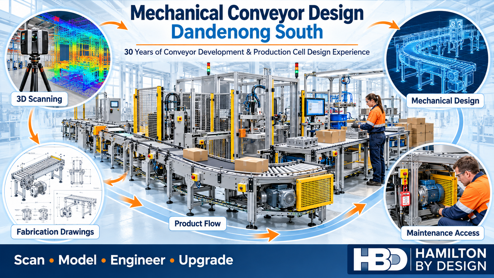
Mechanical Conveyor Design in Dandenong South

Conveyor production cell with 3D scanning, CAD modelling, fabrication drawings and maintenance access illustrations for Hamilton By Design in Dandenong South.

30 Years of Experience Developing Conveyors for Production Cells
Blue line icon of an industrial belt conveyor with rollers, support frame, gearbox and drive motor.

Hamilton By Design provides mechanical conveyor design in Dandenong South for manufacturers planning new production cells, equipment integration and conveyor upgrades. Our principal brings 30 years of experience developing and designing conveyors for production cells, supported by 3D scanning, SolidWorks modelling and fabrication drawings.

For 30 years, the principal at Hamilton By Design has worked on the development and design of conveyors for production cells. That experience shapes a practical approach to moving products between machines, workstations and process stages.

A successful conveyor design starts with understanding your production requirements. What needs to move? How quickly? In what orientation? How will operators interact with the equipment, and how will maintenance staff access it?

By combining mechanical design, 3D modelling, LiDAR scanning and engineering drawings, Hamilton By Design helps businesses develop conveyor arrangements that suit their products, processes and available factory space.

Conveyor Design That Fits Your Production Process

Conveyors connect individual machines into a working production system. Their performance depends on how well they integrate with the equipment upstream and downstream.

A conveyor may need to receive components from a machine, present products to an operator, feed a packaging station or transfer completed assemblies to the next process. Each application has different requirements for speed, spacing, loading and product handling.

Our design process considers:

  • Product dimensions, weight and orientation.
  • Required throughput and operating duty.
  • Conveyor length, width and working height.
  • Transfer points between conveyors and machines.
  • Available floor space and surrounding equipment.
  • Operator access and manual handling.
  • Cleaning, inspection and maintenance requirements.
  • Fabrication, assembly and installation constraints.

The aim is to develop a conveyor arrangement that supports the whole production cell.

New Conveyors and Existing Conveyor Modifications

Hamilton By Design can support new conveyor concepts and targeted modifications to existing systems.

Depending on the application, the mechanical design scope may include belt conveyors, roller conveyors, gravity transfers, product guides, support frames and machine interfaces.

For an existing production line, modifications might involve:

  • Extending or shortening a conveyor.
  • Changing the conveyor height or direction.
  • Connecting new machinery to an existing line.
  • Modifying product guides or transfer arrangements.
  • Replacing deteriorated frames and brackets.
  • Improving maintenance access.
  • Developing guarding and access arrangements.
  • Updating drawings to reflect the equipment installed.

Sometimes a targeted modification provides the improvement a business needs. We begin by understanding the issue and assessing the existing arrangement before developing the design scope.

Integrating Conveyors into Production Cells

Production-cell conveyor design requires attention to the interaction between people, products and machinery.

For example, installing a faster conveyor will not necessarily increase output if the next machine cannot accept products at that rate. Similarly, a compact layout may save floor space while making cleaning or maintenance difficult.

Hamilton By Design considers the proposed conveyor within the wider production process, including:

Product Flow

We assess how products enter, travel through and leave the conveyor. Product stability, spacing and transfer geometry can influence whether the arrangement operates smoothly.

Machine Interfaces

Conveyor heights, entry points and discharge positions need to coordinate with the equipment they serve. Mechanical interfaces should be established early so that brackets, guides and transition details can be developed around agreed dimensions.

Operator Interaction

Loading, unloading, inspection and assembly tasks influence conveyor positioning. The layout should account for how operators carry out their work and move through the production area.

Maintenance Access

Bearings, rollers, drives and adjustment points need suitable access. Considering component removal and maintenance tasks during design helps avoid difficult arrangements after installation.

Electrical controls, sensors and automation interfaces can be coordinated with the clientโ€™s nominated electrical or automation specialists.

3D Scanning Before Conveyor Upgrades

When a new conveyor must fit into an existing factory, reliable information about the surrounding equipment is valuable.

Older drawings may not show machinery relocations, additional services or previous modifications. Measuring only the proposed conveyor footprint can also miss obstructions above or beside it.

Hamilton By Designโ€™s 3D laser scanning services can capture visible existing conditions to support layout planning and mechanical design.

A scan can help establish:

  • Existing conveyor routes and elevations.
  • Machine positions and external geometry.
  • Columns, walls and nearby services.
  • Available space for new equipment.
  • Access routes and installation constraints.
  • Potential clashes with surrounding plant.

Capturing the factory before finalising a layout allows proposed equipment to be assessed against the existing environment.

Where close-tolerance interfaces are required, critical dimensions can be identified for separate verification. This is particularly relevant to mounting holes, shafts, bearings and machined connections.

3D Modelling for Conveyor Layouts

A coordinated 3D model makes the proposed conveyor arrangement easier to review before fabrication begins.

Hamilton By Design uses SolidWorks and CAD tools to develop mechanical assemblies and communicate the relationship between conveyors, machines, support frames and surrounding plant.

Models can support reviews of:

  • Overall conveyor geometry.
  • Product entry and discharge positions.
  • Frame and support arrangements.
  • Drive locations and component access.
  • Guarding envelopes.
  • Installation and assembly space.
  • Interfaces with existing equipment.

Production staff, maintenance personnel and fabricators can review the same arrangement and identify practical issues while changes are still straightforward to make.

For businesses in Dandenong South planning a production-cell upgrade, this provides an opportunity to resolve layout questions before committing to fabrication.

Mechanical Design and Fabrication Drawings

Once the arrangement is agreed, the design can progress into drawings and documentation appropriate to the project.

Our mechanical drafting services can support the manufacture, assembly and installation of new or modified conveyor equipment.

Depending on the agreed scope, deliverables may include:

  • General arrangement drawings.
  • Conveyor assembly drawings.
  • Frame and bracket fabrication details.
  • Sheet-metal and product-guide details.
  • Component drawings.
  • Bills of materials.
  • DXF cutting profiles.
  • STEP files for supplier coordination.
  • Installation and interface drawings.

The documentation package is established around the needs of the client, fabricator and installation team.

Designing for Maintenance and Practical Operation

A conveyor should be assessed over its working life, including the tasks needed to keep it operating.

During design, we consider questions such as:

  • Can the belt or rollers be replaced without dismantling surrounding equipment?
  • Are adjustment points accessible?
  • Can debris be removed from beneath the conveyor?
  • Is there space to inspect and maintain the drive?
  • Can guards be removed and reinstated for authorised maintenance?
  • Are wear components practical to source and replace?

These decisions affect maintenance effort, downtime and the usefulness of the final installation.

Machinery hazards and guarding requirements should also be considered during design. Conveyor safety depends on the complete arrangement, including access, controls, operating procedures and maintenance tasks.

A Practical Process from Concept to Installation Support

Hamilton By Designโ€™s mechanical engineering consulting can be tailored to a focused conveyor modification or a broader production-cell project.

1. Define the Requirement

We discuss the product, production target, existing problems, available space and project timing.

2. Establish Existing Conditions

Relevant drawings, measurements and site information are reviewed. Where useful, 3D scanning captures the surrounding plant.

3. Develop the Concept

Proposed layouts and mechanical arrangements are developed for review with the people who operate and maintain the equipment.

4. Complete the Detailed Design

The agreed concept progresses into component selection, mechanical details and the required design checks.

5. Prepare the Documentation

Models, drawings and supporting information are prepared for the agreed fabrication and installation scope.

6. Support Fabrication and Installation

Where included, we assist with technical queries and review changes that arise during manufacture or installation.

Frequently Asked Questions

Can Hamilton By Design modify an existing conveyor?

Yes. We can assess the existing arrangement and develop mechanical modifications to suit a new machine, revised product flow or changed production requirement.

Do we need a 3D scan for every conveyor project?

No. A straightforward conveyor may be designed using verified measurements and suitable drawings. Scanning is particularly useful where the factory is congested, records are incomplete or several equipment interfaces need coordination.

Can you design a conveyor around our available factory space?

Yes. Available space, equipment positions, access and maintenance requirements can be incorporated into the layout process. Providing information early helps establish the constraints before detailed design begins.

Can you provide drawings for our preferred fabricator?

Yes. The drawing package can be developed around the agreed fabrication scope and your fabricatorโ€™s requirements.

Can you assist before we purchase new machinery?

Yes. Early layout planning can help establish conveyor interfaces, working heights, access requirements and available installation space before machinery positions are finalised.

Discuss Your Conveyor Project in Dandenong South

Are you planning a new production cell, adding machinery or modifying an existing conveyor?

Hamilton By Design brings together 30 years of conveyor development and design experience, mechanical engineering, 3D scanning, CAD modelling and fabrication documentation.

Send us your existing drawings, photographs or a description of the production issue. Include the product being handled, your required throughput and any installation deadline so we can discuss a suitable scope.

Contact Hamilton By Design to discuss mechanical conveyor design in Dandenong South.

Hamilton By Design logo displayed on a blue tilted rectangle with a grey gradient background

Contact Us – Talk To Us

Name
Would you like us to arrange a phone consultation for you?
Address

Our clients:


Related Services for Conveyor and Production Cell Projects

Explore Hamilton By Design services that support conveyor design, factory upgrades and equipment integration in Dandenong South.

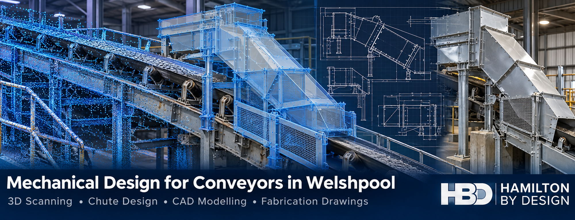
Mechanical Design for Conveyors in Welshpool

Industrial conveyor and transfer chute shown with a LiDAR point cloud, 3D CAD model and fabrication drawing, with the Hamilton By Design logo.

Conveyor upgrades, transfer chutes, 3D scanning and fabrication drawings for industrial facilities in Welshpool, WA

Blue line icon of an industrial belt conveyor with rollers, support frame, gearbox and drive motor.

A conveyor modification has to work with the equipment and space already on site. A replacement chute may need to fit between existing steelwork and services. A new conveyor section may need to connect to equipment whose drawings are incomplete or out of date. Guarding must allow for operation and maintenance as well as the intended installation.

Hamilton By Design brings these tasks together for Welshpool projects. We combine mechanical design, 3D LiDAR scanning, scan-to-CAD, reverse engineering and engineering drafting to help industrial clients move from an existing plant problem to a practical design and documented solution.

Welshpool is a major Perth industrial precinct with manufacturing, engineering, logistics and supply chain businesses. That mix makes conveyor and materials handling work relevant to both production facilities and the workshops that build equipment for projects elsewhere in Western Australia. canning.wa.gov.au

Conveyor design that starts with the existing plant

Conveyor projects often begin with a specific problem: a transfer point that spills material, a worn chute, restricted maintenance access, an equipment replacement or a proposed change to the production layout. The first step is to understand what must change and which parts of the existing installation must be retained.

Hamilton By Design can assist with the mechanical design and documentation of:

  • Conveyor modifications and equipment interfaces
  • Transfer, feed and discharge chutes
  • Hoppers, skirts and wear-liner arrangements
  • Support frames and equipment layouts
  • Machinery guarding and maintenance access
  • Replacement parts where usable drawings are unavailable
  • General arrangement and fabrication drawings

The scope can be tailored to the job. A workshop may need a model and drawings for one replacement assembly. An operating facility may need site capture, design development and an installation drawing package for a wider conveyor upgrade.

3D LiDAR scanning before conveyor modifications

Measurements taken from old drawings do not always represent the installed plant. Conveyor frames may have been altered, supports may have moved during earlier upgrades, and nearby pipework or cable trays may restrict the space available for new equipment.

For a brownfield project, industrial 3D scanning can capture the conveyor and its surrounding area as a point cloud. Relevant geometry can then be used to check proposed equipment locations, clearances and interfaces during design.

Scanning is particularly useful around crowded transfer stations, elevated conveyors and installations where a fabrication or shutdown window leaves little time to resolve a fit-up problem. The required measurements and tolerances should be agreed for each project; critical connection details may still need direct verification. Learn more about scanning conveyor transfer towers.

From point cloud to mechanical design

A point cloud records the existing condition. It becomes more useful when the project team can turn the relevant parts into a model, drawing or design decision.

Hamilton By Designโ€™s scan-to-CAD services for Perth projects can support the modelling of conveyor interfaces, surrounding steelwork and equipment layouts. A proposed modification can then be developed in context, with attention to access, removal paths and the space needed for fabrication and installation.

Depending on the agreed scope, deliverables may include a registered point cloud, a 3D CAD model, general arrangement drawings, fabrication details or files for coordination with the clientโ€™s wider plant model.

Transfer chutes and materials handling

The transfer point affects much more than the space between two conveyors. Material flow, loading position, impact, wear, dust, spillage and access for liner replacement all influence how a chute should be designed.

Hamilton By Design supports chute design and materials-handling engineering for new work and existing installations. For a Welshpool fabrication project, this may mean developing a replacement chute from supplied dimensions and operating information. For an installed plant upgrade, it may mean scanning the transfer area first and designing the new assembly around the actual conveyor and support geometry.

Where a chute is causing repeated maintenance problems, the design brief should identify the material being handled, operating duty, wear locations, cleaning needs and access constraints. Those inputs help define a solution that can be built and maintained, rather than simply reproducing a part that has performed poorly.

Reverse engineering and replacement components

Existing conveyors may have components with no current CAD model or reliable manufacturing drawing. A part may have been modified over time, or a supplier may no longer support the original equipment.

Hamilton By Design can use measurements and reverse-engineering 3D scanning to reconstruct relevant geometry. The resulting model can support a replacement design, drawing update or review of how a component interfaces with the rest of the conveyor.

Reverse engineering also creates an opportunity to examine the original componentโ€™s function and condition. Wear, deformation and previous repairs should be considered before dimensions are carried into a new design.

Drawings that support fabrication and installation

A 3D model helps the team review a proposal, but the workshop and installation team also need clear documentation. Depending on the project, Hamilton By Design can prepare general arrangement drawings, component drawings, assembly details and fabrication information for review and manufacture.

Good documentation makes the intended interfaces visible: what connects to the existing plant, which dimensions need checking on site, how an assembly is broken into transportable pieces and what access is required for installation. Our broader mechanical engineering services connect design, CAD modelling and drafting with the practical needs of plant upgrades.

Support for Welshpool workshops and industrial operators

Hamilton By Design can work with Welshpool fabrication businesses, maintenance teams, manufacturers and project engineers at different stages of a conveyor job.

A fabrication workshop may need a missing component modelled and drawn before it can quote or manufacture a replacement. A facility operator may need to establish the existing geometry before approving a layout change. A project engineer may need a coordinated model and drawing package for review before a shutdown. A maintenance team may need a chute or guard redesigned to improve access to a recurring problem area.

Projects can be scoped around the information already available. Existing drawings, photographs, operating requirements and site measurements provide a starting point; on-site scanning can be added where the installation needs a more complete survey.

Our approach to a conveyor project

  1. Define the problem. Confirm the equipment, operating duty, project boundaries and required deliverables.
  2. Review the existing information. Check drawings, photographs, models and known site constraints.
  3. Capture missing geometry where needed. Measure or scan the relevant conveyor and surrounding plant.
  4. Develop and review the design. Model the proposed change and resolve key interfaces with the client and fabricator.
  5. Issue the agreed documentation. Prepare drawings and model files suited to review, fabrication or installation.

The extent of each stage depends on the project. A small replacement component will need a different package from a multi-conveyor transfer upgrade.

Frequently asked questions

Can you design a replacement chute if our drawings are missing?

Yes. The starting point is to establish the existing interfaces and understand how the chute is expected to perform. Measurements or 3D scanning may be needed before the replacement is modelled and documented.

Do you provide 3D scanning as part of conveyor design?

Yes, where site capture is useful to the project. LiDAR scanning can help document the installed conveyor, support steelwork and surrounding obstructions before a modification is designed.

Can you work with our Welshpool fabricator?

Yes. Hamilton By Design can develop models and drawings for discussion with the nominated workshop, including practical fabrication and installation considerations within the agreed scope.

Can you help with one component rather than a complete conveyor?

Yes. Work can be scoped to a chute section, guard, support, replacement component or other defined mechanical assembly.

Discuss a conveyor project in Welshpool

If you are planning a conveyor upgrade, replacing a transfer chute or trying to document equipment with missing drawings, Hamilton By Design can help establish the existing condition and develop the mechanical design information needed for the next step.

Contact Hamilton By Design with your site location, a short description of the problem, available drawings or photographs, and your intended fabrication or shutdown timeframe.


Hamilton By Design logo displayed on a blue tilted rectangle with a grey gradient background

Contact Us – Talk To Us

Name
Would you like us to arrange a phone consultation for you?
Address

Our clients:


Services That Support Conveyor Projects in Welshpool

A conveyor upgrade can involve site measurement, mechanical design, guarding, analysis and fabrication documentation. Explore the Hamilton By Design services that support each stage.

Mechanical Engineering Services

Mechanical design for conveyors, materials handling equipment and plant modifications, supported by CAD modelling and engineering drawings.

Explore mechanical engineering โ†’

Chute Design and Materials Handling

Develop transfer chutes and related equipment around material flow, wear, maintenance access and the available space within existing plant.

Explore chute design โ†’

Machine Guarding Design

Review and design guarding for conveyor drives, pulleys and other moving machinery while considering operation, cleaning and maintenance.

Explore machine guarding โ†’

Reverse Engineering and 3D Scanning

Reconstruct useful engineering information for conveyor components and assemblies when original models or reliable drawings are unavailable.

Explore reverse engineering โ†’

3D CAD Modelling and Mechanical Drafting

Turn conveyor concepts and measured site information into 3D assemblies, general arrangements and drawings for project review and fabrication.

Explore CAD and drafting โ†’

FEA and Mechanical Assessment

Assess selected mechanical components and support arrangements where loads, stress, deflection or fatigue need closer engineering review.

Explore mechanical assessment โ†’

Scanning Conveyor Transfer Towers

Capture conveyors, chutes, steelwork and nearby services in congested transfer areas before planning an upgrade or replacement.

Explore transfer tower scanning โ†’

Industrial 3D Scanning

Record existing plant conditions as point cloud data to support layout review, scan-to-CAD modelling and brownfield conveyor modifications.

Explore industrial scanning โ†’

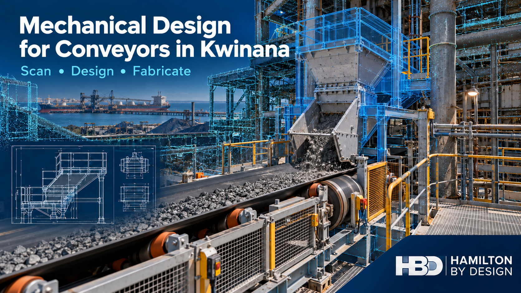
Mechanical Design for Conveyors in Kwinana

Conveyor transfer point in a Kwinana industrial plant with LiDAR and CAD overlays illustrating a proposed mechanical design upgrade.

Mechanical Design for Conveyors in Kwinana

Blue line icon of an industrial belt conveyor with rollers, support frame, gearbox and drive motor.

Conveyor changes need to work with the plant that is already there. Hamilton By Design provides mechanical design support for conveyors in Kwinana and Kwinana Beach, helping industrial teams plan modifications to transfer points, chutes, guarding, access and associated equipment.

A conveyor can appear straightforward on a general arrangement drawing. On site, its performance depends on how material enters and leaves the belt, the position of surrounding steel and services, available maintenance space, and the way components will be installed during a shutdown. A change to one transfer point can affect the equipment on either side.

We combine mechanical engineering, 3D laser scanning, CAD modelling and fabrication documentation to help maintenance managers, project engineers and fabricators develop practical conveyor upgrades. The work can begin with an existing problem, a proposed replacement or an ageing asset with incomplete drawings.

Conveyor engineering in Kwinanaโ€™s industrial environment

Kwinanaโ€™s industrial area includes process facilities, chemicals, minerals processing, energy infrastructure and bulk port operations. These facilities rely on equipment that can be maintained and modified within demanding operating schedules.

For a conveyor project, local conditions may include congested plant, limited shutdown access, abrasive or dusty material, marine exposure, established pipework and steelwork, and interfaces with other operating systems. These conditions need to be assessed for the particular site. They should not be assumed from a standard conveyor drawing.

Hamilton By Design can support the project from existing-condition capture through to mechanical design and drawings for fabrication. Our 3D laser scanning service in Kwinana provides measured site geometry where old drawings are missing or uncertain.

What conveyor components can we help design or modify?

  • Conveyor layouts and interfaces with existing equipment
  • Transfer chutes, hoppers, skirts and wear-liner arrangements
  • Drive, pulley, take-up and support-related mechanical layouts
  • Guards around accessible moving parts and maintenance areas
  • Access platforms, walkways and equipment-removal clearances
  • Replacement brackets, frames, covers and fabricated components
  • Installation arrangements for brownfield modifications
  • General arrangement and fabrication drawings

The design scope depends on the equipment and the problem being solved. A localised chute replacement requires different information from a complete conveyor redesign. We define the required calculations, site checks, specialist input and deliverables before detailed design begins.

Five common conveyor problems

1. Material does not transfer cleanly

Poorly controlled flow at a transfer point can contribute to spillage, dust, blockages and premature wear. The cause may involve the incoming trajectory, chute geometry, impact area, material properties, belt speed or the condition of existing equipment.

We can review the installed arrangement, capture relevant geometry and develop a proposed chute or interface modification in CAD. Depending on the scope, drawings can include liner layouts, replacement parts and fabrication details. Learn more about our chute and materials-handling engineering.

2. The proposed replacement may not fit

A new chute, drive assembly or platform can clash with existing steel, pipework, cable trays or access routes. The problem may only become visible after fabrication, when a shutdown crew is trying to install it.

Engineering-grade LiDAR scanning can establish the surrounding geometry before the new equipment is modelled. We can use the point cloud to review envelopes and likely clashes, then separately verify critical fabrication and installation dimensions. A scan is a strong starting point, but the tolerance of a critical connection must be confirmed for its intended use.

3. Wear makes maintenance too frequent

Abrasive material may wear through a chute, skirt or impact zone well before the rest of the conveyor reaches the end of its service life. Replacing the same component repeatedly may leave the underlying flow or access problem unresolved.

We can document the current arrangement, review reported wear patterns with the maintenance team and develop replaceable wear components or revised geometry. Inspection and removal access should be considered alongside the life of the component.

4. Guards are difficult to remove or leave hazards exposed

Conveyors include pulleys, belts, drives and other moving parts that can create entanglement and nip-point hazards. A guard needs to prevent access to the hazard while supporting the actual tasks performed by operators and maintainers.

Hamilton By Design can assist with measured guarding concepts and fabrication drawings. Guarding should be developed with the siteโ€™s task-based risk assessment, isolation procedures and machinery-safety requirements. Our machine guarding service explains this approach.

5. Maintenance access was overlooked

A component may fit the available space yet be difficult to inspect, lift out or replace. When designing a modification, we consider access to inspection points, fasteners, liners, guards and equipment-removal paths. The arrangement should also be reviewed against the siteโ€™s lifting and shutdown plan.

From site survey to fabrication drawings

For an existing conveyor, our workflow can be scaled to the project:

  1. Define the operating problem. Review material, duty, failure history, maintenance tasks and the proposed outcome with the site team.
  2. Capture existing conditions. Review available drawings and measure or scan the conveyor and surrounding interfaces.
  3. Develop design options. Model practical arrangements for flow, fit, wear, guarding and access.
  4. Check the design. Undertake agreed mechanical assessment and coordinate any required structural, electrical, process or specialist review.
  5. Prepare documentation. Issue general arrangements, part and assembly drawings, liner layouts or fabrication details suited to the agreed scope.
  6. Support implementation. Resolve design queries and record changes where fabrication or site installation requires them.

Depending on the project, we can provide registered point clouds, SolidWorks models, AutoCAD drawings, STEP files, PDF drawing packs and other agreed formats. Our Perth mechanical and industrial drafting service covers the drawing stage in more detail.

Standards and conveyor safety

Applicable standards must be selected for the conveyor type, site, hazards and design scope. The AS/NZS 4024 Safety of Machinery series includes conveyor-specific requirements and broader guidance for risk assessment and safeguarding. AS 1657 may be relevant to fixed platforms, walkways, stairs and ladders associated with access.

For a shiploader, stacker, reclaimer or other mobile bulk-handling machine, AS 4324.1 may be relevant to the design of its steel structure. Other mechanical, structural, electrical and hazardous-area requirements need to be established with the responsible disciplines.

Design work also needs to align with the operatorโ€™s plant-risk assessment, isolation procedures and management of change. Drawings alone cannot control how a conveyor is cleaned, operated or maintained. The site team must review the proposed arrangement against the tasks people actually perform.

Who we support

Our conveyor design support is intended for Kwinana maintenance teams planning a replacement, project engineers developing a plant upgrade, fabrication workshops needing reliable drawings, and operators reviewing transfer performance, wear or access.

For port and bulk-handling equipment, our shiploader 3D scanning page explains how measured data supports modifications to conveyors, chutes, booms and access systems. Our Perth mechanical engineering page covers wider brownfield design support.

Frequently asked questions

Can you design a replacement chute for an existing conveyor?

Yes, subject to the information available and an agreed scope. We would review the existing geometry, material and operating problem before developing the replacement arrangement and drawings.

Do you need to scan the whole conveyor?

Not always. A localised modification may only require the transfer point, adjacent equipment and installation path. A wider upgrade may need more extensive capture. The scan boundary should follow the design decision.

Can you work from old drawings?

Yes, but critical interfaces should be checked against the physical asset before fabrication. Existing drawings are useful references even when later site modifications have made them incomplete.

Can you provide fabrication drawings?

Yes. Depending on the scope, deliverables may include general arrangements, assembly and part drawings, liner details and installation references. The required tolerances, materials and review responsibilities should be agreed before issue.

Can you review conveyor guarding?

We can assist with mechanical guarding concepts, site measurement and drawings. The final control strategy must account for the equipment, access frequency, maintenance tasks, isolation arrangements and applicable machinery-safety requirements.

Discuss a conveyor project in Kwinana

If a conveyor, transfer chute or guarding arrangement in Kwinana needs modification, contact Hamilton By Design. Send the site location, photographs or drawings, material handled, current problem, shutdown window and the outcome you need. We can then define the survey, engineering and drawing scope.


Hamilton By Design logo displayed on a blue tilted rectangle with a grey gradient background

Contact Us – Talk To Us

Name
Would you like us to arrange a phone consultation for you?
Address

Our clients:


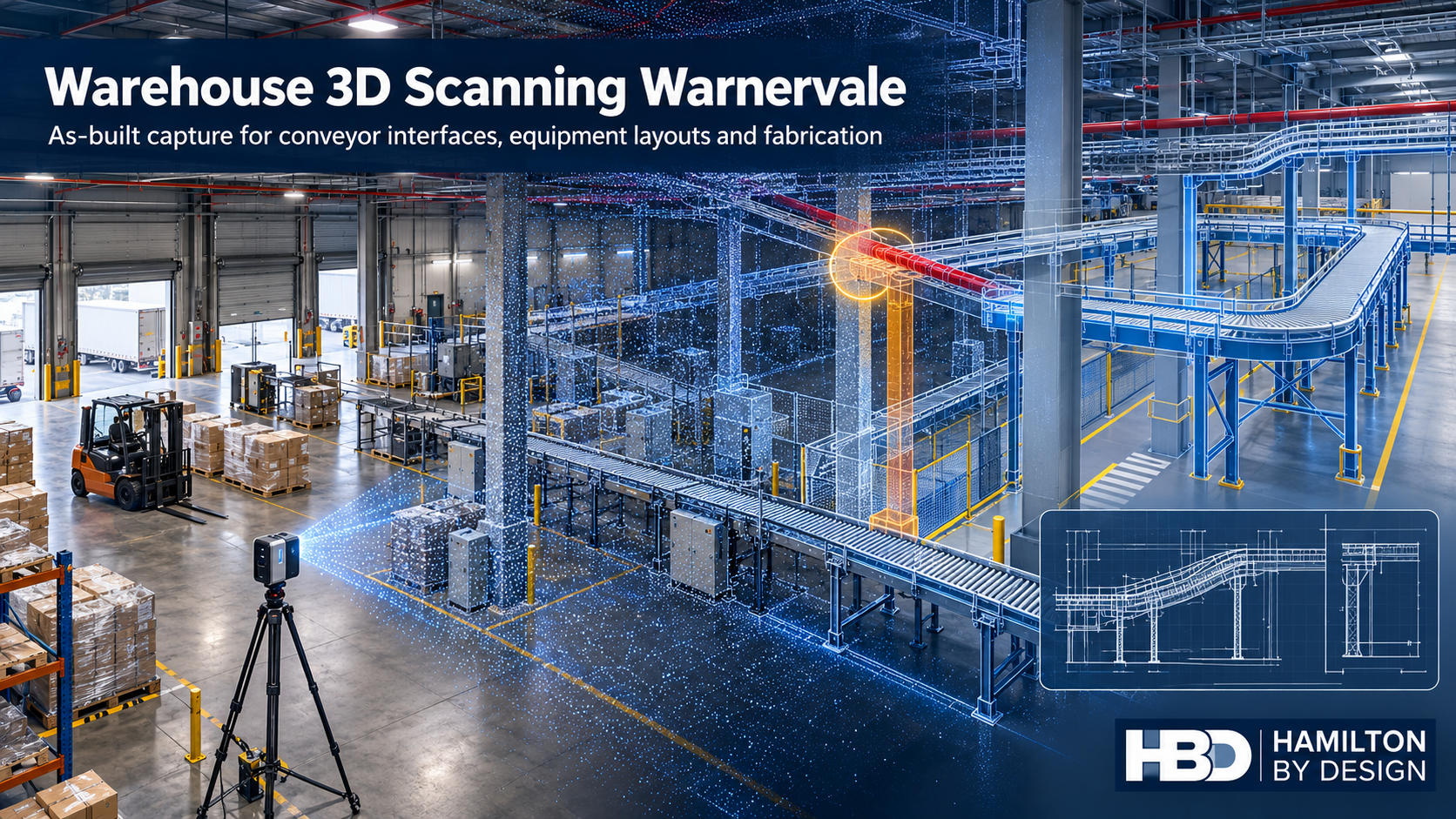
Warehouse 3D Scanning in Warnervale: Designing Around What Is Actually There

Illustration of a Warnervale warehouse showing a laser scanner, point cloud, conveyor clash and revised CAD layout.
Blue 3D LiDAR scanner icon on a tripod with scanning waves

A warehouse fit-out often begins with a clean drawing. The building on site may tell a different story. A column is slightly out of position, a service crosses the proposed conveyor route, or equipment installed after handover occupies space shown as clear on the original plan. Each difference matters when a new system must be fabricated and installed while the warehouse keeps operating.

Hamilton By Design provides warehouse 3D scanning in Warnervale, NSW, to establish the existing conditions before layouts and mechanical details are finalised. We can turn the scan into a point cloud, an as-built drawing or a CAD model suited to the decision the client needs to make. From there, our mechanical design and drafting services can support conveyor interfaces, equipment layouts and fabrication documentation.

For a new facility, the question may be, โ€œWhat was actually built?โ€ For an established distribution centre, it is more likely, โ€œWill the proposed change fit without disrupting the operation?โ€ Both questions are better answered before components arrive on site.

Why Warnervale needs its own approach

Warnervale is more than a name on a Central Coast service-area list. Its business park sits close to the M1 and Sparks Road interchange, beside Central Coast Airport and near the railway. The precinct includes established distribution activity, while the wider Warnervale area is identified for further industrial, manufacturing, logistics and warehouse uses. That creates two kinds of engineering work: adapting facilities already in use and preparing newer buildings for their first equipment fit-out.

The businesses in and around the precinct illustrate its range. Woolworths has a distribution-centre property at Warnervale. PFD Foodservice has identified a new Warnervale site, while Coastal Transport Services lists its depot and head office on Burnet Road. Sanitarium lists a Development & Innovation location at Warnervale; its listed Central Coast factory is at Berkeley Vale. These examples describe local activity, not projects undertaken by Hamilton By Design.

There is also a geographical detail worth getting right. Warnervale Business Park and Warner Business Park are different developments; the latter is in nearby Jilliby. A facility’s address and site boundaries should be confirmed before its layout, access or planning conditions are discussed.

The point where a drawing becomes an installation problem

Consider a proposed conveyor through an occupied warehouse. On a concept drawing, its route may appear straightforward. On site, the installation team must work around columns, doors, overhead services, existing machines, pedestrian routes and maintenance access. A support frame may need to land in a narrow space that has never been measured for that purpose.

An as-built scan records the visible geometry of the relevant area. The registered point cloud can then be used to review the proposed conveyor against the building and existing equipment. Depending on the project, HBD can develop plan views, sections, selected equipment models and installation details. The aim is to identify difficult interfaces while there is still time to change the design.

This is the connection between 3D LiDAR scanning in Wyong and surrounding areas and practical warehouse engineering. The scan is a starting point for decisions: where the equipment can go, what needs to be moved, which dimensions require direct verification and what the fabricator needs to know.

What should be captured in a Warnervale warehouse?

Scanning an entire building is not automatically the right scope. A project to install one transfer conveyor may need detailed coverage of its route, support locations, connection points and nearby services. A broader warehouse reconfiguration may require a coordinated record of the floor, columns, docks, major equipment and circulation spaces.

A useful scoping discussion starts with the proposed change. HBD can then identify which of the following need to be captured:

  • Building columns, walls, doors, slab levels and relevant overhead features.
  • Existing conveyors, machines, guards and access platforms.
  • Equipment connection points and spaces needed for operation or maintenance.
  • Loading and movement areas affected by a layout change.
  • Selected dimensions that must be checked directly before fabrication.

A point cloud contains a great deal of information, but it does not automatically verify every fabrication dimension. Critical interfaces should be identified early, given suitable access and checked to the tolerance required by the work. HBDโ€™s 3D scanning for fabrication service in Wyong explains how site capture can support components and installation layouts intended to fit existing assets.

From as-built scanning to a workable layout

A warehouse layout has to do more than fit equipment inside a building. It must allow materials to move through the operation and give people room to use, clean and maintain the equipment. A conveyor positioned solely by its footprint may block access to a door or leave too little room to remove a component later.

HBD can use the scan as a reference for alternative equipment positions and mechanical interfaces. The output might be a straightforward two-dimensional floor plan, a three-dimensional model of a congested area, or fabrication drawings for supports and brackets. The required level of detail depends on whether the client is exploring options, seeking approval for a layout or ready to manufacture components.

Our wider Central Coast point-cloud-to-CAD workflow connects site capture with usable models and drawings. For projects that need equipment modification as well as measurement, mechanical engineering services on the Central Coast can support the design and fabrication stages.

3D laser scanning in Warnervale is particularly useful when several contractors are working from different assumptions. A shared as-built reference helps the warehouse operator, equipment supplier, mechanical designer and fabricator discuss the same physical constraints. It also provides a baseline against which later changes can be recorded.

Five problems to resolve before a fit-out

The first problem is unreliable existing drawings. Construction drawings show design intent, while the installed facility may have changed during construction or operation. An as-built survey establishes the features relevant to the proposed work.

The second is equipment that fits on paper but clashes on site. Conveyor routes and machine envelopes should be checked against columns, services, doors and adjacent plant before supports or components are made.

Third is limited installation access. Fabrication drawings need to account for how a component will be brought into the building, positioned and connected. Measuring the final location alone may miss the route required to get it there.

Fourth is the interaction between equipment and people. A layout change can alter access to machinery or the way workers and vehicles move through an area. The operatorโ€™s risk assessment should consider those changes. Scan data and CAD layouts can help document the geometry, but the scan itself is not a safety assessment.

Fifth is the loss of a reliable engineering record. When a project finishes, its measured information can be more valuable than the original concept drawing. Subject to the clientโ€™s agreed confidentiality and retention arrangements, HBD can retain factory point clouds, machine models, conveyor layouts, CAD files, fabrication drawings and equipment-interface information for future modifications.

A record that supports the next change

Warehouses rarely stay in their original arrangement. A tenant may introduce a new product line, move a machine, alter a conveyor or change how an area is used. Each change is easier to plan when the project team can locate a dependable record of the previous one.

That does not mean modelling every bolt in the building. A useful digital record is organised around purpose: the areas captured, the date and revision, the features modelled, and any limits on how the data should be used. When fabrication is involved, the record should also distinguish between general scan geometry and dimensions specifically verified for manufacture.

For an owner or operator, this gives future teams a clearer starting point. For a fabricator, it reduces the number of assumptions hidden in a drawing. For a project manager, it makes an interface question easier to resolve before it becomes a site delay.

Frequently asked questions

Can HBD scan a warehouse that is still operating?

Yes, subject to site access, induction and a suitable scan plan. The survey can be organised around the areas needed for the project. An active site may require coordination with vehicle movements, equipment use and restricted work areas.

Does a new warehouse need as-built scanning if construction drawings already exist?

It may, particularly before closely fitting conveyors, machinery or fabricated supports are installed. The scan can check the relevant built geometry against the proposed equipment layout. The extent of scanning should reflect the fit-out risk rather than an assumption that the whole building needs a detailed model.

What is included in scan to CAD for a Warnervale factory fit-out?

That depends on the agreed deliverables. It may include a registered point cloud, a two-dimensional layout, selected three-dimensional building or machine geometry, sections through congested areas, and drawings for mechanical or fabrication work. HBD can define those outputs with the client before scanning.

Can warehouse scanning help with conveyor design?

Yes. Scanning can establish the available route and the position of existing equipment, structure and services. Mechanical design is then needed to develop the conveyor arrangement, supports and interfaces. The scan provides measured context; it does not design the conveyor by itself.

Is a point cloud accurate enough to fabricate from?

Accuracy depends on the scanner


Hamilton By Design logo displayed on a blue tilted rectangle with a grey gradient background

Contact Us – Talk To Us

Name
Would you like us to arrange a phone consultation for you?
Address

Our clients:


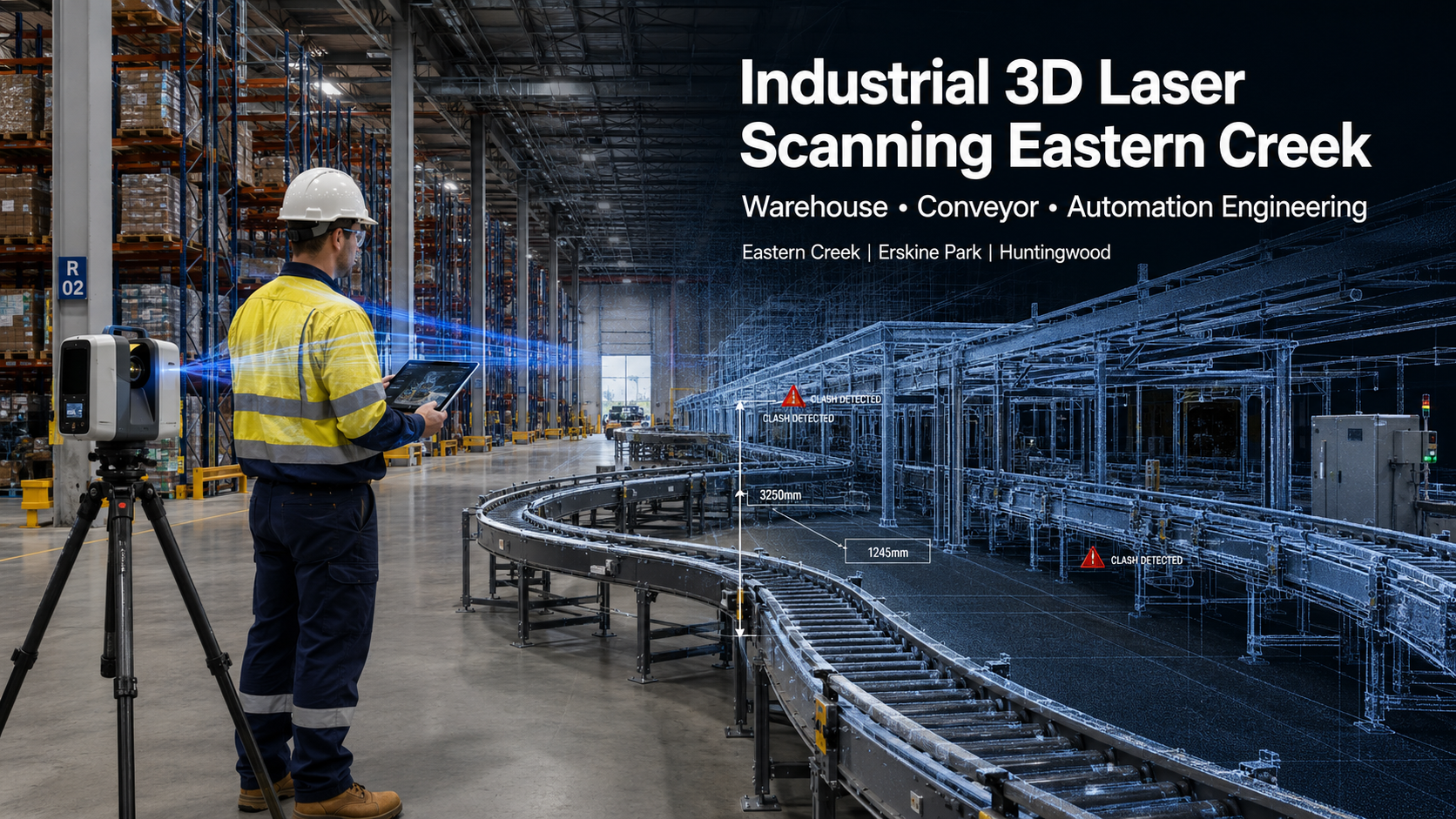
Industrial 3D Laser Scanning Eastern Creek | HBD

Engineer using a 3D laser scanner inside an automated Eastern Creek warehouse with conveyors, racking and a point-cloud model.

Industrial 3D Laser Scanning Eastern Creek for Warehouses, Conveyors and Automation

Blue 3D LiDAR scanner icon on a tripod with scanning waves

Eastern Creek, Erskine Park and Huntingwood form one of Western Sydneyโ€™s major industrial and logistics areas. The precinct supports large warehouses, automated distribution centres, manufacturers and transport businesses. Inside these facilities, conveyors, racking, machinery, services and automation must work together within increasingly congested spaces.

The challenge is that many industrial buildings change faster than their drawings. Equipment is relocated, conveyors are extended, production lines are upgraded and structural supports are added, but the original plans may never be fully updated. When another project begins, engineers and contractors can be forced to design from incomplete information.

Hamilton By Design provides industrial 3D laser scanning services throughout Eastern Creek, Erskine Park, Huntingwood and Western Sydney. We combine reality capture with mechanical engineering, point-cloud modelling and fabrication-aware design to reduce uncertainty before equipment is manufactured or installed.

A Major Industrial and Logistics Precinct

Eastern Creek is located near the M4 and M7 motorways and is surrounded by Erskine Park, Huntingwood and Arndell Park. The region contains large industrial buildings used for distribution, logistics, manufacturing, storage, packaging and automated fulfilment.

These operations depend on physical interfaces. A new conveyor must align with existing equipment. An automated cell must fit between columns, racking and services. A maintenance platform must provide safe access without obstructing forklifts or production. Even a small dimensional error can affect fabrication, installation and commissioning.

Traditional measurements can miss the relationships between services, floors, structures, equipment and access routes. Industrial laser scanning captures these elements as a coordinated three-dimensional dataset, providing a more complete basis for design.

The Problem with Outdated Facility Drawings

The biggest risk in a brownfield warehouse or factory project is often the difference between the documented facility and the facility that actually exists.

Legacy drawings may show the original construction but not later modifications. Supplier models may represent individual machines without accurately locating them inside the building. Conveyor contractors, automation integrators and structural designers may also work in different coordinate systems or from different revisions.

This can result in:

  • Clashes between conveyors, columns, racking and building services
  • Incorrect floor levels or equipment interface positions
  • Support steel that does not fit the existing structure
  • Inadequate operating and maintenance clearances
  • Repeated site visits and late design changes
  • Additional fabrication work or on-site modification
  • Delays during restricted installation or shutdown periods

Hamilton By Designโ€™s 3D point-cloud modelling services in Sydney turn site information into practical CAD geometry, layouts and as-built documentation. The objective is usable engineering information that supports coordination, fabrication and installationโ€”not simply a visual model.

Warehouse and Factory Scanning Applications

Industrial 3D laser scanning can be applied to an entire facility or a defined project area. Typical applications in Eastern Creek, Erskine Park and Huntingwood include:

  • Warehouse and factory floor layouts
  • Conveyor routes, transfers, merges and sortation systems
  • Production, packaging and pallet-handling lines
  • Automated storage and retrieval system interfaces
  • Loading docks, dispatch areas and mezzanines
  • Columns, roof framing and equipment support steel
  • Pipework, ducting, cable trays and other building services
  • Maintenance platforms, walkways and access stairs
  • Proposed machinery installation or relocation zones

Registered point clouds let the project team revisit the facility digitally and take additional measurements without arranging a new visit for every question. This is valuable where access is restricted or scanning must be completed during a short maintenance window.

From Point Cloud to Mechanical Engineering

A point cloud becomes most valuable when it is connected to an engineering purpose. Hamilton By Design can use scan data as the basis for mechanical engineering services in Sydney, including equipment layouts, conveyor modifications, machinery integration, access platforms, guards, supports and retrofit designs.

A typical workflow begins by confirming the capture area, accuracy and deliverables. The facility is scanned using terrestrial or mobile LiDAR. The scans are registered and checked before being imported into CAD and coordination platforms.

Depending on the project, the next stage may include:

  1. Developing an existing-condition model
  2. Inserting supplier equipment or automation models
  3. Positioning conveyors and mechanical interfaces
  4. Checking clashes, clearances and maintenance access
  5. Designing supports, platforms, guards or modifications
  6. Preparing general arrangement and fabrication drawings
  7. Scanning the completed installation to update the as-built record

Hamilton By Designโ€™s SolidWorks 3D modelling services support mechanical assemblies, fabricated equipment and installation interfaces. AutoCAD, Inventor and Navisworks can also suit the clientโ€™s engineering workflow.

Mechanical Engineering for Manufacturing Facilities

Manufacturing sites may require more than a building survey. A production-line change can affect material flow, machine guarding, operator access, maintenance space and the supporting structure.

Hamilton By Design provides manufacturing layout design for factories and production facilities. Services can include machinery arrangements, production and packaging layouts, conveyor integration, support steel, access systems, fabrication documentation and installation planning.

Where the strength or stiffness of a modified frame or equipment support must be assessed, finite element analysis and mechanical assessment can be incorporated when suitable loads, materials and boundary conditions are available.

Applicable requirements may include the AS/NZS 4024 machinery-safety series, AS/NZS 4024.3610 for conveyor systems, AS 1657 for fixed platforms and access systems, AS 3990 for mechanical-equipment steelwork, AS 4100 for steel structures and the AS/NZS 1170 structural design actions series. The standards and editions applying to a particular project should be confirmed during scoping and design review.

Engineering Support for Logistics and Automation

Automated distribution centres bring together conveyors, sorters, scanners, robotic equipment, racking, controls and warehouse-management systems. While Hamilton By Designโ€™s core role is mechanical and spatial rather than control-system programming, accurate geometry is essential to each interface.

Scanning can establish conveyor elevations, column positions, racking clearances, maintenance zones and structural connections. Proposed automation can then be coordinated against the facility before installation.

For projects involving steel storage racking, AS 4084.1 addresses design while AS 4084.2 covers operation and maintenance. Mechanical guarding and conveyor safety may require consideration of the AS/NZS 4024 series, while electrical work must be completed by appropriately qualified professionals in accordance with applicable electrical requirements.

Hamilton By Design can also produce mechanical drafting and fabrication documentation for conveyor supports, platforms, guards, brackets, assemblies and installation arrangements.

Maintaining a Reliable Digital As-Built Record

The value of the project data can continue after installation. Subject to agreed ownership, confidentiality, security and retention requirements, Hamilton By Design can retain registered point clouds, facility layouts, conveyor models, structural interfaces, CAD assemblies, drawings and installation records.

These files can support later upgrades, maintenance planning and asset verification. Information can also be organised using principles discussed in Hamilton By Designโ€™s ISO 19650 and Scan-to-BIM guidance.

Industrial 3D Laser Scanning Eastern Creek

For operators planning a warehouse expansion, conveyor modification, automation project or production-line upgrade, accurate existing-condition information can reduce risk before fabrication begins.

Hamilton By Design provides industrial scanning across Eastern Creek, warehouse scanning in Erskine Park, conveyor engineering support in Huntingwood and industrial scanning throughout Western Sydney. We connect the real facility with mechanical design, clash detection, fabrication documentation and as-built verification.

Frequently Asked Questions

What can be captured during an industrial 3D laser scan?

Laser scanning can capture floors, columns, framing, conveyors, machinery, racking interfaces, platforms, pipework, ducting and visible services. The scope should focus on elements needed for the engineering task.

Can an operational warehouse be scanned?

Yes. Scanning can be planned around operations, traffic controls and restricted access. Staged, weekend or after-hours scanning may reduce disruption and improve equipment visibility.

Can point clouds be used for conveyor modifications?

Yes. Existing conveyor geometry and the surrounding structure can be captured so that new sections, transfers, supports and access requirements are developed against actual site conditions.

What files can Hamilton By Design provide?

Depending on the agreed scope, deliverables may include E57, RCP, RCS or LAS point clouds; DWG or DXF drawings; STEP, SAT or SolidWorks models; PDFs; general arrangements; fabrication drawings; and as-built documentation.

Does scanning replace mechanical engineering design?

No. Scanning establishes accurate existing geometry, but loads, materials, safety risks, structural performance and compliance still require engineering consideration. Hamilton By Design combines scanning with practical mechanical design where this is included in the project scope.

Can scanning identify clashes before installation?

Yes. Proposed equipment and supplier models can be positioned within the existing-condition model to identify spatial conflicts, restricted access and interface problems before fabrication or site installation.

Can Hamilton By Design retain the facility data for future projects?

Yes, subject to an agreement covering ownership, confidentiality, access, security and retention. Future modifications can then begin with an established digital record.

Which locations are covered?

Hamilton By Design can support industrial facilities in Eastern Creek, Erskine Park, Huntingwood, Arndell Park and across the wider Western Sydney region.


Hamilton By Design logo displayed on a blue tilted rectangle with a grey gradient background

Contact Us – Talk To Us

Name
Would you like us to arrange a phone consultation for you?
Address

Our clients:


Explore additional Hamilton By Design services supporting warehouse scanning, conveyor engineering, automation projects, manufacturing upgrades and industrial facilities throughout Western Sydney.

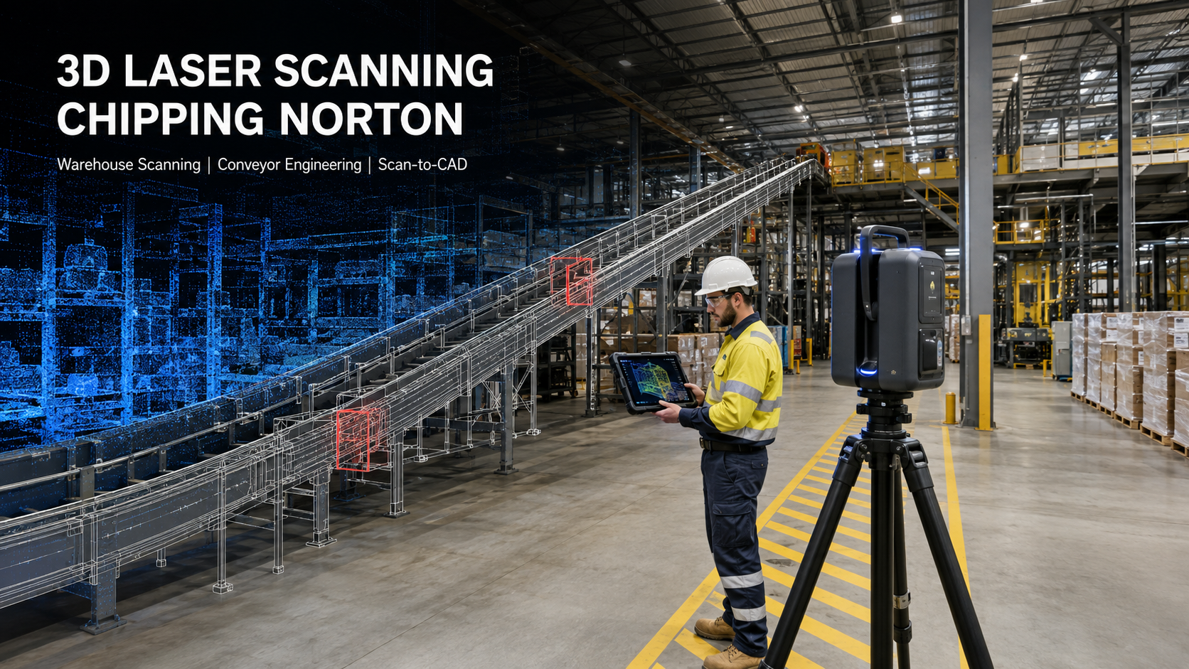
3D Laser Scanning Chipping Norton | Warehouse & Conveyor Engineering

Engineer using 3D laser scanning to capture a warehouse conveyor system in Chipping Norton NSW.
Blue 3D LiDAR scanner icon on a tripod with scanning waves

Chipping Norton and Moorebank form an important industrial corridor within Greater Sydney. The region combines established manufacturing and fabrication businesses with large warehouses, automated distribution centres, freight infrastructure and materials-handling operations. This concentration of industrial activity creates an ongoing requirement for accurate existing-condition information when facilities are expanded, upgraded or modified.

For many brownfield projects, the principal engineering challenge is not developing the proposed design. It is establishing exactly what is already installed.

Original drawings may be incomplete, machinery may have been repositioned, conveyor systems may have been extended and structural elements may differ from their documented positions. These discrepancies can create clashes, fabrication errors, installation delays and unplanned shutdown work.

Hamilton By Design provides engineer-led industrial 3D scanning services for manufacturers, warehouse operators, automation specialists, engineering consultants and contractors working throughout Chipping Norton, Moorebank and Greater Sydney. LiDAR scanning can capture existing warehouses, machinery, conveyors, platforms, structural steel and building services, creating a reliable foundation for engineering design and accurate plant layouts.

An Important Manufacturing and Logistics Precinct

Chipping Norton has a long-established industrial character. Its factories and commercial properties accommodate manufacturing, machinery, metal fabrication, HVAC equipment, packaging, engineering services and general industrial production.

Nearby Moorebank has become a nationally significant logistics location. The area contains extensive warehousing, intermodal freight infrastructure and increasingly sophisticated automated distribution operations. Major organisations with operations or developments in the wider precinct include Primary Connect and Woolworths Group, Kmart Group, Maersk, Mainfreight and other logistics and warehouse operators.

These facilities may contain kilometres of conveyors, automated storage systems, pallet-handling equipment, robotic cells, loading infrastructure, racking, mezzanines and supporting structures. Even apparently straightforward modifications can involve complex interfaces between mechanical equipment, structural steel, electrical services, fire systems and existing building elements.

Hamilton By Design combines reality capture with mechanical engineering consulting to help project teams understand these interfaces before fabrication or installation begins.

The Biggest Brownfield Engineering Problem

The greatest problem facing existing factories and warehouses is uncertainty about actual site conditions.

A facility may have an original building plan, a separate conveyor drawing and several equipment layouts produced at different times. However, no single drawing may accurately represent the complete operating facility. Maintenance work, machinery replacements and production changes can gradually create substantial differences between the documented arrangement and the installation on site.

Common problems include:

  • Outdated or incomplete plant layouts
  • Undocumented machinery relocations
  • Conveyor supports that differ from design drawings
  • Structural columns located differently from the available CAD model
  • Incomplete records of platforms, stairs and access systems
  • Building services passing through proposed equipment zones
  • Insufficient maintenance and removal clearances
  • Proposed automation conflicting with existing machinery
  • Floor levels or structural interfaces that have not been verified
  • Limited shutdown periods for checking dimensions

Traditional tape measurements and manual site surveys remain valuable for isolated dimensions, but they can become inefficient where thousands of interconnected measurements are required. They may also fail to capture secondary elements that later become important to the design.

Engineering-grade LiDAR scanning records the visible facility as a coordinated three-dimensional dataset. This allows designers to review dimensions, positions, levels and clearances without relying solely on multiple return visits.

Developing Accurate Plant and Warehouse Layouts

An accurate plant layout should represent the facility as it existsโ€”not merely reproduce an old drawing in a new CAD format.

Hamilton By Design can scan the relevant production or warehouse area and process the captured information into a registered point cloud. Depending on the project requirements, that data can then be used to prepare:

  • Existing-condition warehouse layouts
  • Machinery and production-line arrangements
  • Conveyor routes, centrelines and elevations
  • Structural column and beam locations
  • Equipment operating envelopes
  • Maintenance and removal clearances
  • Access-platform and stair layouts
  • Sections and elevations
  • Mechanical and structural CAD models
  • General arrangement drawings
  • As-built documentation

The required modelling detail can be matched to the engineering purpose. A broad warehouse-planning study may only require the building envelope, columns, major services and equipment zones. A conveyor modification may require more detailed modelling of support frames, transfer points, guarding and adjacent machinery.

This fit-for-purpose approach reduces unnecessary modelling while ensuring that critical design interfaces are captured accurately.

Warehouse Scanning in Moorebank

Warehouse scanning can support more than the preparation of a building plan. In a modern distribution facility, the relationship between the building and the installed operating systems is often critical.

A three-dimensional warehouse survey can record floor areas, structural grids, underside-of-roof clearances, mezzanines, racking, conveyors, platforms, loading areas and equipment locations. The resulting information may support:

  • Warehouse automation projects
  • Conveyor extensions or alterations
  • New picking and packing systems
  • Racking modifications
  • Equipment relocation
  • Tenant fit-outs
  • Loading-dock upgrades
  • Fire and building-services coordination
  • Maintenance-access reviews
  • Facility expansion planning
  • As-built asset records

For larger or more complex facilities, scanning can be undertaken in planned stages to suit operating restrictions and access requirements. The resulting point cloud provides a visual and measurable record of the surveyed conditions at that time.

Where building-focused modelling is needed, Hamilton By Design can also provide Scan-to-BIM services to convert relevant existing-condition information into a coordinated digital model.

Conveyor Engineering and Materials Handling

Conveyors and automated materials-handling systems are particularly sensitive to dimensional errors. Belt lines, transfer heights, support locations, head and tail pulley positions, maintenance access and surrounding structures must be considered together.

A proposed conveyor may appear to fit on a two-dimensional plan but clash with roof bracing, pipework, platforms or building columns when reviewed in three dimensions. Transfer points may also require adequate space for chutes, guarding, access doors and maintenance activities.

Hamilton By Design can use point-cloud data to establish the existing geometry before developing conveyor modifications or supporting structures. The workflow may include:

  1. Capturing the existing conveyor and surrounding area
  2. Establishing conveyor centrelines, levels and support positions
  3. Modelling important structures and equipment interfaces
  4. Incorporating the proposed conveyor or chute arrangement
  5. Reviewing the design for physical clashes
  6. Checking access, removal and maintenance envelopes
  7. Preparing general arrangements and fabrication documentation

Hamilton By Designโ€™s experience in manufacturing and production projects enables the scan data to be interpreted as engineering information rather than treated only as a visual record.

Clash Checking Before Installation

Clash checking allows the proposed design to be compared with the scanned facility before materials are ordered or equipment is delivered.

The proposed machinery, conveyor, platform or structure can be positioned within the point cloud or existing-condition CAD model. Potential conflicts can then be identified between the new design and existing columns, conveyors, services, structures or access routes.

Clash checking is particularly useful where:

  • Installation tolerances are limited
  • Prefabricated assemblies must fit existing structures
  • Shutdown time is restricted
  • Large equipment must follow a defined installation path
  • Maintenance access must remain available
  • Multiple contractors are working within the same area
  • Automation equipment has strict operating clearances

Resolving these issues digitally can reduce site cutting, drilling, welding and last-minute fabrication. It can also provide project stakeholders with a clearer understanding of the proposed installation.

Reverse Engineering Existing Machinery

Manufacturing businesses frequently operate machinery for which reliable drawings are no longer available. The original manufacturer may no longer support the equipment, or the installed machine may have been modified throughout its operating life.

Hamilton By Design can use reverse-engineering 3D scanning to capture the geometry of machinery, components and interfaces. Scan information can then support the development of replacement parts, equipment modifications or new CAD records.

Reverse engineering may be suitable for:

  • Obsolete machinery components
  • Guards and covers
  • Conveyor components
  • Transition pieces and ducting
  • Chutes and hoppers
  • Support frames
  • Mounting arrangements
  • Replacement fabricated assemblies
  • Components that must interface with existing equipment

The objective is not always to produce an identical copy. The captured geometry can provide a starting point for reviewing fit, function, material selection, service requirements and opportunities for improvement.

From Point Cloud to Fabrication Drawings

A point cloud is valuable, but most projects require the information to progress into an engineering deliverable.

Hamilton By Design can convert relevant scan data into SolidWorks, Autodesk Inventor or AutoCAD models and drawings. The appropriate outputs depend on whether the project is intended for planning, detailed design, fabrication, installation or asset retention.

The scan-to-CAD and fabrication drawing process can produce:

  • Mechanical CAD models
  • Existing and proposed layouts
  • General arrangement drawings
  • Fabrication assembly drawings
  • Detail drawings
  • Parts lists
  • Structural steel models
  • Sections and elevations
  • DWG and DXF profiles
  • STEP, SAT or Parasolid models
  • Installation reference drawings

This integrated workflow reduces the risk of information being lost between the site survey, design team and fabricator.

Retaining a Reliable Digital Engineering Record

Point clouds and CAD models can provide continuing value after the immediate project has been completed. Subject to the agreed confidentiality and data-management requirements, HBD can retain warehouse scans, conveyor layouts, structural interfaces, equipment envelopes, clash records and as-built models.

This information can form a baseline for later plant changes, maintenance work or warehouse expansion. Rather than beginning each new project with another incomplete set of drawings, the facility owner can progressively develop a more reliable digital engineering record.

Frequently Asked Questions

What is 3D laser scanning?

3D laser scanning uses LiDAR technology to capture visible surfaces and their spatial positions. The collected measurements form a point cloud representing the scanned warehouse, factory, machinery or structure.

Can an operating warehouse be scanned?

Yes. Scanning can often be completed while a warehouse remains operational, subject to site access, safety requirements and the movement of vehicles, people and equipment. The survey can be staged around operational restrictions.

Can you produce an accurate plant layout from the scan?

Yes. The point cloud can be used to develop a fit-for-purpose plant or warehouse layout showing structural grids, machinery, conveyors, platforms, equipment zones and other required features.

Can scanning help with a new conveyor installation?

Yes. Scanning can establish existing conveyor locations, support positions, elevations, structures and nearby services. The proposed conveyor can then be modelled and checked for clashes before fabrication.

What file formats can be supplied?

Typical point-cloud formats include E57, RCP, RCS and LAS. CAD deliverables may include DWG, DXF, STEP, SAT, Parasolid, SolidWorks or Inventor formats, depending on the agreed project scope.

Can HBD prepare fabrication drawings?

Yes. Hamilton By Design can progress from site scanning and CAD development to general arrangements, fabrication assemblies, detail drawings, parts lists and DXF cutting profiles where required.

Does every object need to be modelled?

No. The modelling detail should reflect the intended engineering use. Critical interfaces can be modelled accurately without recreating every visible object within the point cloud.

What areas do you service?

Hamilton By Design supports projects throughout Chipping Norton, Moorebank, Liverpool, Milperra, Bankstown, Prestons and the wider Greater Sydney industrial region.

Discuss a Chipping Norton or Moorebank Project

Accurate existing-condition information can reduce uncertainty before warehouse modifications, conveyor installations, plant upgrades or fabrication begin.

Hamilton By Design provides engineering and 3D scanning services in Sydney for manufacturers, warehouse operators, automation specialists and project engineers. Contact Hamilton By Design to discuss 3D laser scanning in Chipping Norton, warehouse scanning in Moorebank, conveyor engineering, reverse engineering or the development of accurate plant layouts.


Hamilton By Design logo displayed on a blue tilted rectangle with a grey gradient background

Contact Us – Talk To Us

Name
Would you like us to arrange a phone consultation for you?
Address

Our clients: