How Smart Mechanical Strategies Extend CHPP Life
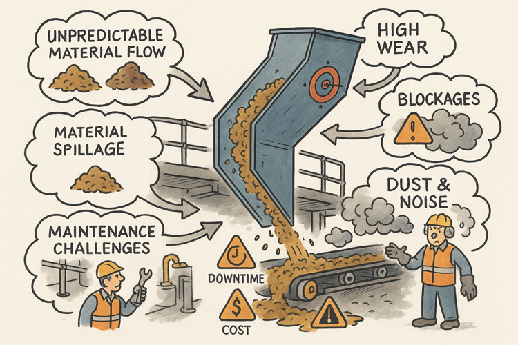
Every coal wash plant in Australia tells the same story: constant throughput pressure, harsh operating conditions, and the never-ending battle against wear, corrosion, and unplanned downtime. The reality is simple — if you don’t engineer for reliability, you’ll spend your time repairing failure.
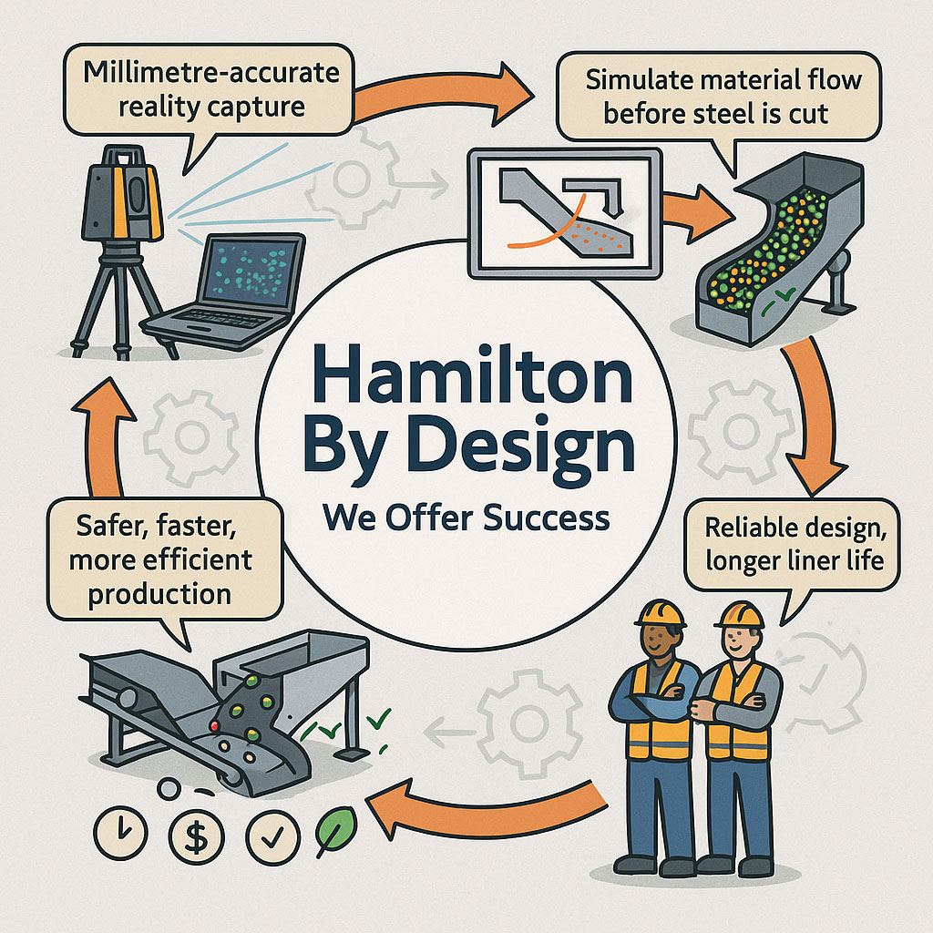
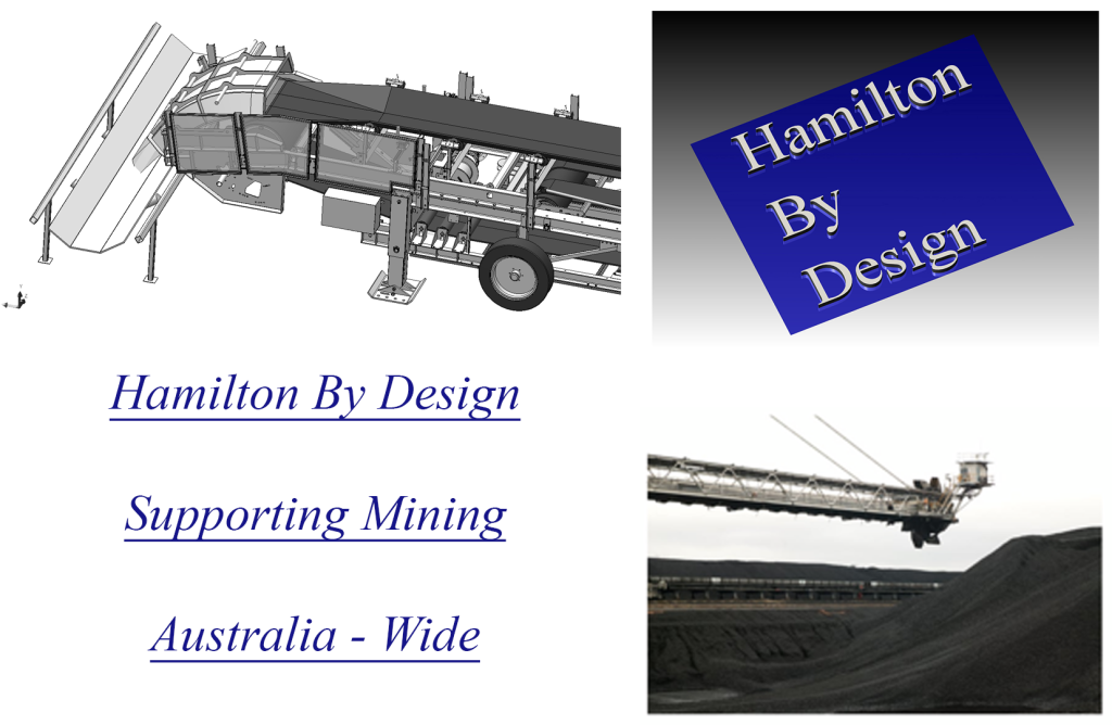
At Hamilton By Design, we specialise in mechanical engineering, 3D scanning, and digital modelling for coal handling and preparation plants (CHPPs). Our goal is to help site teams transition from reactive maintenance to a precision, data-driven strategy that keeps production steady and predictable.
Design for Reliability — Not Reaction
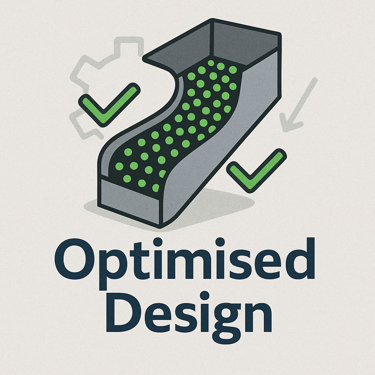
Reliability begins with smart mechanical design. Poor geometry, limited access, and undersized components lead to fatigue and repeated downtime. Instead, modern CHPP maintenance programs start by engineering for fit, lift, and life:
- Fit: Design components that align with the existing structure — every bolt, flange, and mating face verified digitally before fabrication.
- Lift: Incorporate certified lifting points that comply with AS 4991 Lifting Devices, and ensure clear access paths for cranes or chain blocks.
- Life: Select wear materials suited to the physics of the process — quenched and tempered steel for impact, rubber or ceramic for abrasion, and UHMWPE for slurry lines.
It’s not just about parts; it’s about engineering foresight. A well-designed plant component is safer to install, easier to inspect, and lasts longer between shutdowns.
Scan What You See — Not What You Think You Have
Over time, every wash plant drifts from its original drawings. Field welds, retrofits, and corrosion mean that “as-built” and “as-exists” are rarely the same thing.
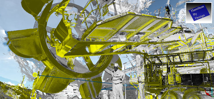
That’s where LiDAR scanning transforms maintenance. Using sub-millimetre accuracy, 3D laser scans capture your plant exactly as it stands — every pipe spool, every chute, every bolt hole.
With this data, our engineers can:
- Overlay new models directly into your point cloud to confirm fit-up before fabrication.
- Identify alignment errors, corrosion zones, and clearance conflicts before shutdowns.
- Generate true digital twins that allow for predictive maintenance and simulation.
LiDAR scanning isn’t just a measurement tool; it’s an insurance policy against rework and lost production.
Corrosion: The Hidden Killer in Every CHPP
Coal and water don’t just move material — they create acidic environments that eat through untreated or aging steel. In sumps, launders, and under conveyors, corrosion silently compromises strength until a structure is no longer safe to walk on.
Regular inspections are the first line of defence. At Hamilton By Design, we recommend combining:
- Daily visual checks by operators for surface rust and coating damage.
- Thickness testing during shutdowns to track wall loss on chutes and pipes.
- 3D scan comparisons every 6–12 months to quantify deformation and corrosion in critical structures.
With modern tools, you can see corrosion coming long before it becomes a failure.
From Data to Decision: Predictive Maintenance in Action
A coal wash plant produces a river of data — motor loads, vibration levels, pump pressures, liner thickness, and flow rates. The key is turning that data into insight.
By integrating scanning results, maintenance records, and sensor data, plant teams can identify trends that point to future breakdowns. For example:
- Vibration trending can reveal bearing fatigue weeks before failure.
- Load monitoring can detect screen blinding or misalignment.
- Scan data overlays can show sagging supports or displaced chutes.
When you understand what your plant is telling you, you move from reacting to problems to predicting and preventing them.
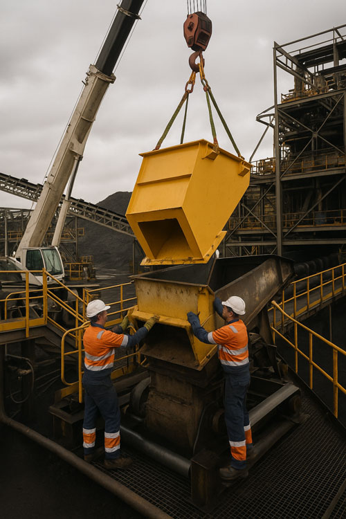
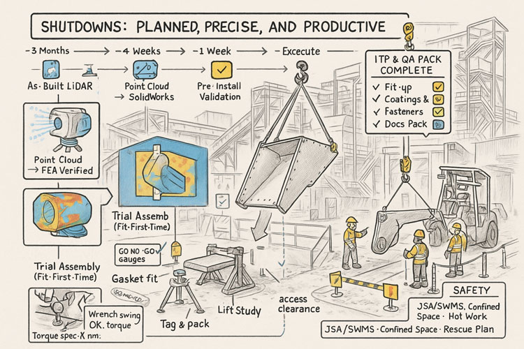
Shutdowns: Planned, Precise, and Productive
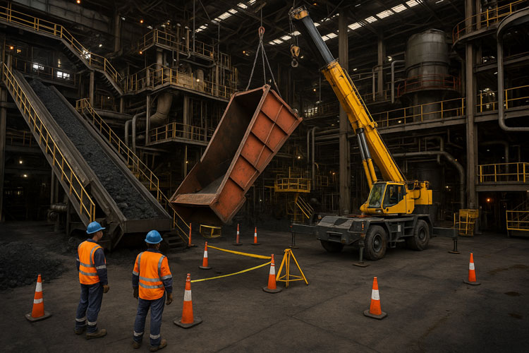
Every shutdown costs money — the real goal is to make every hour count. The best shutdowns start months ahead with validated design data and prefabrication QA.
Before you cut steel or mobilise cranes, every component should be digitally proven to fit. Trial assemblies, lifting studies, and bolt access checks prevent costly surprises once you’re on the clock.
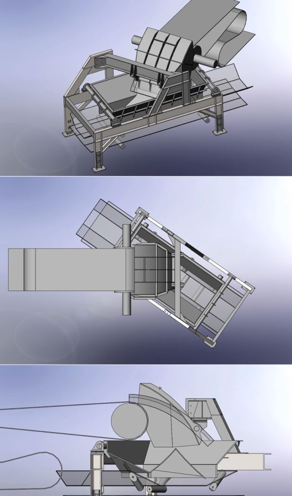
At Hamilton By Design, our process combines:
- LiDAR scanning to confirm as-built geometry.
- SolidWorks modelling and FEA for mechanical verification.
- Pre-installation validation to ensure bolt holes, flanges, and lift paths align on day one.
That’s how you replace chutes, spools, and launders in a fraction of the usual time — safely, and with confidence.
The Payoff: Reliability You Can Measure
The plants that invest in engineering-led maintenance see results that are tangible and repeatable:
| Improvement Area | Typical Gain |
|---|---|
| Reduced unplanned downtime | 30–40% |
| Increased liner lifespan | 25–50% |
| Shorter shutdown duration | 10–20% |
| Fewer fit-up issues and rework | 60–80% |
| Improved safety performance | 20–30% |
Reliability isn’t luck — it’s engineered.

Your Next Step: A Confidential Mechanical Assessment
Whether your plant is in the Bowen Basin, Hunter Valley, or Central West NSW, our team can deliver a confidential mechanical and scanning assessment of your wash plant.
We’ll benchmark your current maintenance strategy, identify high-risk areas, and provide a clear roadmap toward predictive, engineered reliability.
📩 For a confidential assessment of your current wash plant, contact:
info@hamiltonbydesign.com.au
Stop reacting. Start engineering. Build reliability that lasts.
Our clients:


Mechanical Engineering | Structural Engineering
Mechanical Drafting | Structural Drafting