Why Conveyor Transfer Chute Design Matters

3D CAD model of a conveyor transfer chute with a feed conveyor at 90 degrees stacking ore into a conical stockpile

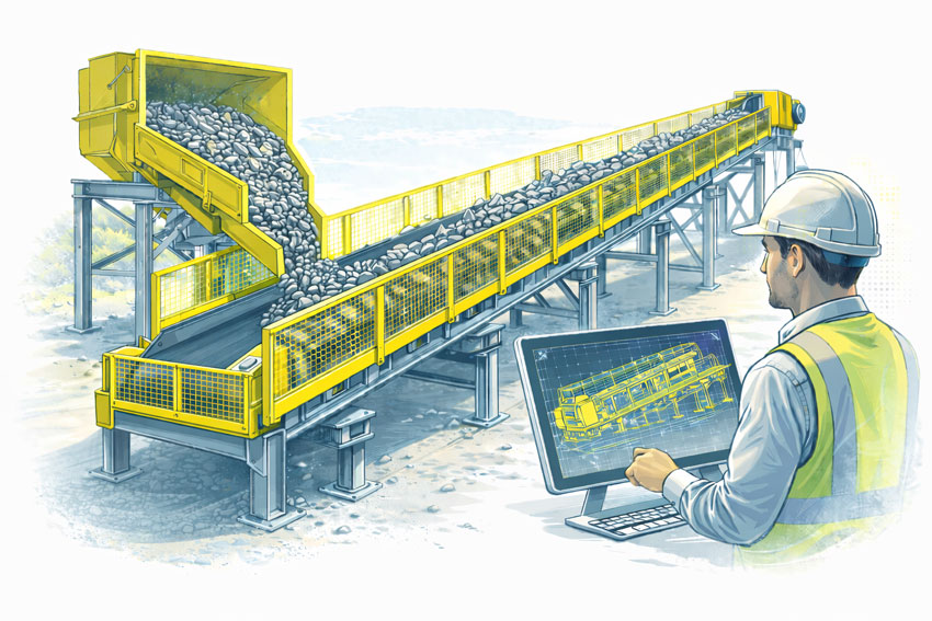
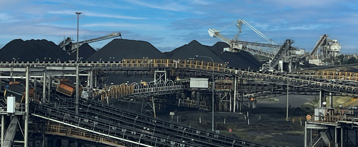
In mining plants, conveyor transfer chutes are often the most overlooked component in the materials handling system. Yet they are frequently responsible for the largest operational disruptions.

Poor chute design can result in:

  • Material blockages
  • Conveyor belt damage
  • Excessive wear on liners
  • Dust generation
  • Product spillage
  • Reduced plant throughput

For mining operations running 24/7 production, even minor transfer issues can escalate into significant downtime during shutdowns.

Effective conveyor transfer chute design is therefore not just a drafting exerciseโ€”it is a critical engineering task that directly impacts plant reliability, maintenance costs, and safety.


Common Problems in Mining Transfer Chutes

Across many mining and processing plants, similar issues appear repeatedly in poorly designed transfer points.

Typical operational problems include:

1. Blockages and Build-Up

Moist ores, fine materials, and poorly directed material streams often lead to material accumulation. Over time this causes:

  • chute choking
  • restricted flow paths
  • emergency shutdowns

2. High Impact Loading

If the chute does not properly control the material trajectory, large rocks can strike belts or liners at high velocity, resulting in:

  • conveyor belt damage
  • excessive wear on liners
  • structural fatigue

3. Material Spillage

Incorrect chute geometry can cause material to miss the receiving belt entirely. Spillage creates:

  • safety hazards
  • housekeeping issues
  • unnecessary cleanup labour

4. Dust and Environmental Issues

High drop heights and uncontrolled material flow generate dust clouds that affect:

  • operator safety
  • equipment life
  • compliance with environmental requirements

Engineering Principles Behind Reliable Chute Design

Reliable conveyor transfer chute design requires understanding both material behaviour and mechanical systems.

Some key design considerations include:

Controlled Material Flow

The goal of a well-designed chute is to control the material stream, ensuring that the ore flows smoothly onto the receiving conveyor at the correct velocity and direction.

Design considerations include:

  • trajectory modelling
  • flow velocity management
  • impact angle control

Wear Management

Mining materials are extremely abrasive. Chute design must incorporate wear protection strategies such as:

  • replaceable liner systems
  • ceramic or chromium carbide plates
  • sacrificial wear zones

A well-designed chute allows liners to be replaced quickly during shutdowns.


Belt Protection

Poorly designed transfers can dramatically reduce conveyor belt life.

Engineering improvements often include:

  • impact beds
  • loading skirts
  • properly aligned material streams

Reducing belt damage significantly lowers maintenance costs.


Maintenance Accessibility

A transfer chute should be designed with maintainability in mind.

This includes:

  • safe inspection access
  • removable panels
  • maintenance platforms
  • quick liner replacement systems

These features become particularly important during tight shutdown windows.


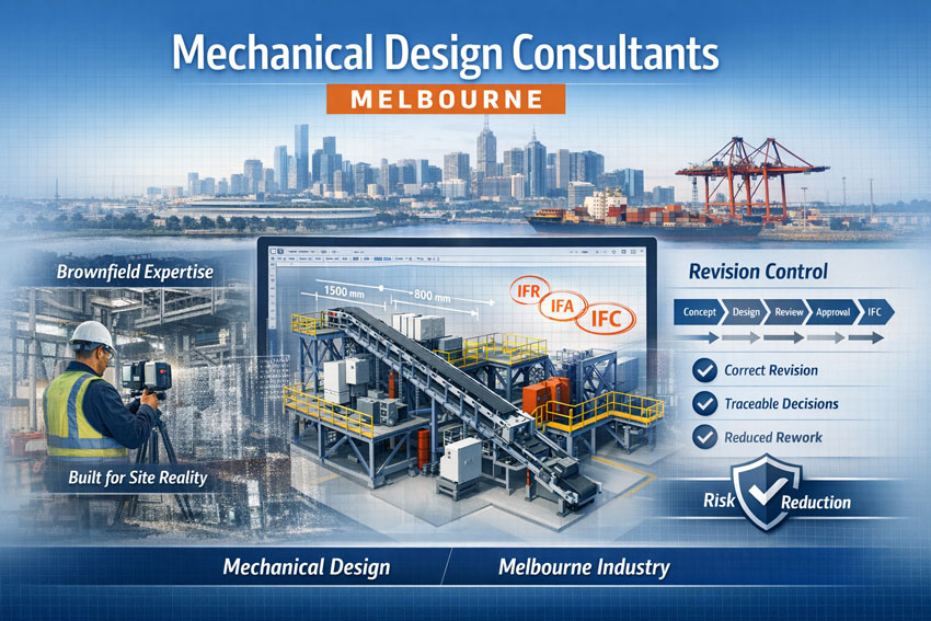
Using Digital Engineering to Improve Chute Performance

Modern mining operations increasingly rely on digital engineering tools to improve the reliability of transfer points.

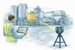
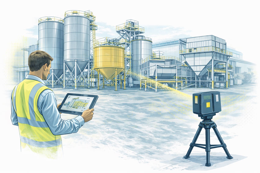
Technologies such as 3D laser scanning and digital plant models allow engineers to:

  • capture the exact geometry of existing plant infrastructure
  • analyse transfer trajectories
  • redesign chutes within existing plant constraints
  • reduce risk during shutdown installations

This approach is particularly useful when retrofitting new chutes into older mining infrastructure where original drawings are often incomplete or inaccurate.

More information on this workflow can be found in:


Designing Transfer Chutes for Shutdown Installations

In many cases, chute upgrades are installed during planned mining shutdowns, where time is extremely limited.

Engineering preparation is essential to ensure the work can be completed within the shutdown window.

Typical preparation includes:

  • capturing existing plant conditions
  • producing accurate engineering models
  • clash detection with existing structures
  • fabrication-ready drawings

A well-prepared digital model significantly reduces the risk of installation delays.

Further discussion on shutdown engineering preparation can be found here:


Mechanical Engineering Support for Mining Infrastructure

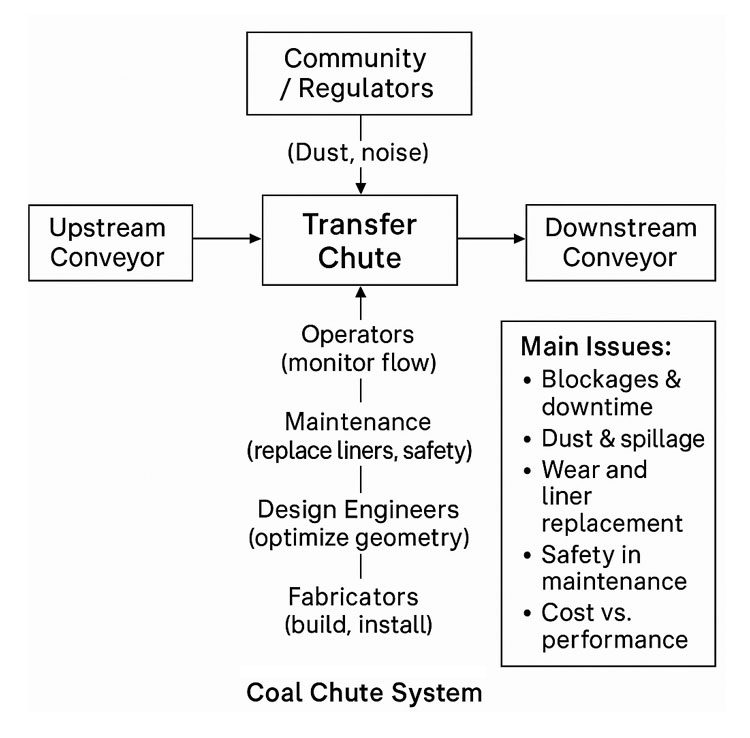
Reliable transfer chute systems require collaboration between:

  • mechanical engineers
  • plant operators
  • maintenance teams
  • fabrication workshops

By combining operational experience with digital engineering tools, mining companies can significantly improve the reliability of their materials handling systems.

Hamilton By Design provides mechanical engineering design services for mining infrastructure, including:

  • conveyor transfer chute design
  • materials handling upgrades
  • plant modification design
  • digital engineering models for shutdown work

Learn more about these services here:


Hamilton By Design logo displayed on a blue tilted rectangle with a grey gradient background

Final Thoughts

Transfer chutes may appear to be a simple part of a conveyor system, but their impact on mining operations is significant.

Poorly designed chutes lead to:

  • downtime
  • safety risks
  • excessive maintenance costs

With careful engineering design, digital modelling, and proper shutdown preparation, transfer points can become reliable components of a high-performance mining plant.

For operations seeking to reduce downtime and improve plant reliability, conveyor transfer chute design is one of the most valuable engineering improvements available.

3D LiDAR scanning and 3D modelling service button โ€” laser scanner capturing a point cloud for engineering and CAD modelling
Mechanical engineering services
Name
Would you like us to arrange a phone consultation for you?
Address
CHPP Engineering title graphic featuring bold white text reading "CHPP Engineering" centred on a blue rounded rectangle background.
Pipework Drafting title graphic featuring bold white text reading "Pipework Drafting" centred on a blue rounded rectangle background.
3D LiDAR Scanning for Engineering Projects title graphic featuring bold white text on a blue rounded rectangle background.
Finite Element Analysis (FEA) engineering simulation button
Mechanical engineering services

Mechanical Design Consultants Melbourne

Melbourne mechanical engineering consultancy showcasing governed CAD design, brownfield expertise and controlled drawing revisions.

Mechanical Design Consultants Melbourne | Hamilton By Design

Melbourneโ€™s industrial landscape is evolving rapidly โ€” advanced manufacturing, logistics automation, food processing, infrastructure upgrades and brownfield plant modifications are all demanding stronger mechanical design capability and tighter governance.

At Hamilton By Design, we provide mechanical design consulting services to Melbourne-based businesses that need more than drawings โ€” they need clarity, compliance and confidence.


What We Deliver

As mechanical design consultants servicing Melbourne, our focus is practical engineering solutions that can be built, maintained and certified.

1. Mechanical Design & Drafting

  • 2D and 3D CAD modelling
  • Plant layout development
  • Conveyor and materials handling systems
  • Structural interface coordination
  • Detailed fabrication drawings

2. Brownfield & Upgrade Projects

Melbourne facilities are often live environments. We understand:

  • Working within existing constraints
  • Coordinating multi-vendor inputs
  • Managing drawing revisions (IFR / IFA / IFC)
  • Ensuring installation-ready documentation

3. Engineering Governance

High labour costs in Australia mean rework is expensive. We help you avoid:

  • Building to the wrong drawing revision
  • Supplier misalignment
  • Poor documentation control
  • Unverifiable design assumptions

Our governance approach includes:

  • Revision-controlled drawing systems
  • Structured issue states
  • Design change tracking
  • Documented decision pathways

Industrial mechanical design consultants Melbourne delivering plant modelling, site scanning and engineering governance.

Why Melbourne Clients Choose Mechanical Design Consultants Instead of โ€œJust Draftingโ€

There is a significant difference between drafting and engineering design.

Drafting produces geometry.
Engineering design produces accountable outcomes.

We focus on:

  • Load paths
  • Maintainability access
  • Compliance pathways
  • Constructability
  • Lifecycle thinking

That means fewer RFIs, fewer shutdown overruns and clearer certification pathways.


Mechanical Design Consultants Melbourne โ€“ Industries We Support

We regularly assist projects in:

  • Manufacturing facilities
  • Distribution centres
  • Mining and materials handling
  • Waste and recycling infrastructure
  • Food and beverage processing
  • Energy and utilities

Whether it is a small plant modification or a staged facility upgrade, structured mechanical design reduces downstream risk.


Our Difference: Design + Governance

Many consultants provide CAD. Few provide engineering governance integrated with design delivery.

We combine:

  • 3D scanning and point cloud verification
  • Solid modelling and layout coordination
  • Revision control systems
  • ISO-aligned documentation structures
  • Digital engineering workflows

This means your mechanical design is not just created โ€” it is controlled, traceable and defendable.


When Should You Engage a Mechanical Design Consultant?

You should consider engaging mechanical design consultants in Melbourne when:

  • You are modifying existing plant
  • Multiple vendors are contributing drawings
  • You require certification
  • You need clarity before fabrication
  • You want to reduce rework risk

The earlier structured engineering is introduced, the lower the total project cost.


Supporting Melbourne Projects from Concept to Construction

Hamilton By Design supports:

  • Concept feasibility
  • Detailed mechanical design
  • Fabrication documentation
  • Site coordination
  • As-built documentation
  • Governance setup for future upgrades

We operate with a practical, industry-informed mindset โ€” designs must work not just in CAD, but on site.


Hamilton By Design logo displayed on a blue tilted rectangle with a grey gradient background

3D LiDAR scanning and 3D modelling service button โ€” laser scanner capturing a point cloud for engineering and CAD modelling
Mechanical engineering services

Mechanical Design Consultants Melbourne โ€“ Letโ€™s Talk

If your project requires structured mechanical design support with governance discipline, we welcome the opportunity to assist.

Contact Hamilton By Design to discuss your Melbourne project requirements and how we can help deliver engineering clarity, reduced risk and confident outcomes.


Name
Would you like us to arrange a phone consultation for you?
Address
3D CAD Modelling Australia service banner for Hamilton By Design

3D Laser Scanning in Rockhampton QLD: Engineering-Grade Data for Safer Conveyor Design and Risk Management

Engineering-led SolidWorks drafting in Australia with 25 years of Hamilton By Design experience

3D Laser Scanning in Rockhampton QLD for Safer Conveyor Design & Risk Management

Rockhampton plays a critical role in Central Queenslandโ€™s heavy industry, supporting mining, bulk materials handling, agriculture, and transport infrastructure. Across these sectors, conveyor systems are essential โ€” and they are also one of the highest-risk assets on site.

As facilities age and production demands increase, many operators are upgrading or modifying conveyors within tight shutdown windows. In these environments, engineering-grade 3D laser scanning (LiDAR) is becoming a key tool for reducing design risk, improving safety outcomes, and avoiding costly site rework.

At Hamilton By Design, we use high-accuracy 3D scanning to capture existing plant conditions and convert them into reliable engineering models that support safer conveyor design and more effective risk management.

Conveyor Systems and Industry Incidents: Where Things Go Wrong

Industry incident investigations across Queensland repeatedly identify similar contributing factors in conveyor-related injuries:

  • Inadequate guarding at transfer points and pulleys
  • Restricted access forcing unsafe maintenance practices
  • Plant modifications made without updated drawings
  • Design reviews based on outdated or incomplete site data

In regional facilities around Rockhampton, conveyors are often extended, repaired, and repurposed over many years. What starts as a temporary modification can become permanent, and original drawings no longer reflect reality on the ground.

When new upgrades are designed using assumptions instead of accurate geometry, risk is built into the project from day one.


Bulk materials conveyor with compliant safety guarding at the hopper, tail end, and along the conveyor, shown with an engineer reviewing guarding design drawings.

Why Engineering-Grade Scanning Matters for Conveyor Design

Not all 3D scans are suitable for mechanical design or safety-critical decisions.

We use engineering-grade LiDAR scanning capable of delivering accuracy in the order of ยฑ2 mm over 70 metres, allowing engineers to:

  • Model conveyor structures, frames, and supports
  • Accurately locate rollers, drives, guards, and transfer chutes
  • Verify clearances for new equipment and walkways
  • Identify clashes before fabrication and installation

The resulting point clouds and CAD models form a reliable digital baseline that engineers, safety teams, and maintenance planners can all work from.

When plant modifications are driven by accurate data, both design quality and safety outcomes improve.

Safe Design Starts with Knowing What Actually Exists

Safe Design is not something that can be retrofitted easily once steel is fabricated and installed.

Scan-based models allow hazards to be assessed during the design phase, including:

  • Access and egress routes for maintenance
  • Reach distances and pinch point exposure
  • Guarding coverage around rotating equipment
  • Space constraints that may encourage unsafe shortcuts

This is particularly important in conveyor corridors where multiple services, structures, and walkways compete for limited space.

Designing from accurate site geometry allows risks to be eliminated or reduced before they reach the worksite.


Risk Management Through Reality Capture

From a risk management perspective, 3D scanning supports more than just design accuracy. It also improves:

  • Hazard identification and risk assessments
  • Method statements and installation planning
  • Shutdown coordination and contractor interfaces
  • Compliance documentation and audit trails

Point cloud data also provides a permanent record of asset condition at a point in time, which can be invaluable for:

  • Future upgrade planning
  • Incident investigations
  • Asset integrity assessments

In high-risk conveyor environments, reliable data is a control measure in its own right.

Supporting Rockhampton Industry with Integrated Engineering Services

Hamilton By Design provides on-site 3D scanning and mechanical engineering support for projects in Rockhampton and Central Queensland, including:

  • Conveyor upgrades and replacements
  • Transfer point redesigns
  • Guarding and access improvements
  • Brownfield plant modifications
  • Fabrication and installation planning

Because we are an engineering-led team, scanning is directly integrated into mechanical design, drafting, and fabrication support โ€” not treated as a standalone survey service.

This ensures models are built to suit engineering workflows and deliver practical, buildable outcomes.


Hamilton By Design logo displayed on a blue tilted rectangle with a grey gradient background

3D LiDAR scanning and 3D modelling service button โ€” laser scanner capturing a point cloud for engineering and CAD modelling
Mechanical engineering services

From Point Cloud to Practical Results

Our typical workflow includes:

  1. On-site LiDAR scanning with minimal operational disruption
  2. Registration and processing of point cloud data
  3. Conversion into CAD models suitable for mechanical design
  4. Design development, safety reviews, and shop drawings

This approach reduces shutdown risk, improves installation accuracy, and helps ensure safety improvements are achieved in practice โ€” not just on paper.

Name
Would you like us to arrange a phone consultation for you?
Address
3D LiDAR scanning and 3D modelling service button โ€” laser scanner capturing a point cloud for engineering and CAD modelling
Mechanical engineering services
Finite Element Analysis (FEA) engineering simulation button
Mechanical engineering services

AS 3774 โ€“ Loads on Bulk Solids Containers: Why It Matters for Safety and Compliance

Engineer using 3D LiDAR scanner to capture silos, hoppers, bins, and bulk solids containers at an industrial processing plant.

AS 3774 โ€“ Loads on Bulk Solids Containers | Safety & Compliance

AS 3774 Loads on Bulk Solids Containers exists for a simple reason:
bulk solids do not behave like fluids, and incorrect load assumptions can create serious structural and safety risks.

For asset owners, engineers, and project teams involved in mining, mineral processing, manufacturing, and bulk materials handling, AS 3774 provides the framework for understanding how loads actually develop in silos, bins, hoppers, chutes, transfer stations, and surge bins.

Yet despite its long-standing availability, many new installations are still being delivered without full consideration of AS 3774 load cases.

The risks created by this gap are often not immediately visible โ€” but they are very real.


Engineer using 3D LiDAR scanner to capture silos, hoppers, bins, and bulk solids containers at an industrial processing plant.

What AS 3774 Is Designed to Address

AS 3774 recognises that bulk solids behave in complex and sometimes counter-intuitive ways. Unlike liquids, bulk materials:

  • Develop non-uniform wall pressures
  • Apply eccentric and asymmetric loads
  • Change load paths depending on flow behaviour
  • Generate dynamic and cyclic forces during filling and discharge

The standard provides guidance for determining realistic design loads based on how material actually flows and interacts with container geometry.

This applies across all bulk solids containers, including:

  • Silos
  • Bins and surge bins
  • Hoppers
  • Chutes and transfer stations
  • Rail and ship loading structures
  • Feeders integrated with bins

Why Safety and Compliance Depend on AS 3774

The purpose of AS 3774 is not academic. It exists to prevent outcomes such as:

  • Progressive wall deformation
  • Fatigue cracking and bolt failure
  • Local buckling or plate tearing
  • Uncontrolled discharge or blockage release
  • Unexpected load transfer into supporting structures

What makes these issues particularly dangerous is that they often develop over time, not at commissioning.

A structure can appear โ€œfineโ€ on day one โ€” while accumulating damage due to:

  • Cyclic loading
  • Eccentric discharge patterns
  • Inaccurate assumptions about material properties
  • Mixed construction materials behaving differently over time

Common Design Assumptions That Create Hidden Risk

In practice, many bulk solids containers are still designed using simplified or incorrect assumptions, including:

1. Treating Bulk Solids Like Fluids

Uniform hydrostatic pressure assumptions do not reflect real wall loading patterns and can significantly under-predict peak stresses.

2. Ignoring Eccentric Discharge

Off-centre outlets, partial blockages, or asymmetric flow paths can introduce large bending and torsional effects that are not obvious from geometry alone.

3. Incorrect or Assumed Material Properties

Bulk density, cohesion, moisture content, and flow behaviour are often assumed rather than verified โ€” yet small changes can have large load implications.

4. Mixed Materials Without Long-Term Consideration

It is not uncommon to see hoppers fabricated from a combination of stainless steel and mild steel, without adequate consideration of:

  • Differential stiffness
  • Fatigue behaviour
  • Corrosion mechanisms
  • Galvanic interaction

These issues may not present as immediate failures, but they can significantly reduce structural life and reliability.


Why the Risk Is Often Not Evident Today

One of the most concerning aspects of non-compliance with AS 3774 is that failure is rarely immediate.

Instead, risk accumulates quietly through:

  • Repeated filling and discharge cycles
  • Minor operational changes
  • Variations in material condition
  • Small geometric imperfections

By the time visible cracking, deformation, or operational issues appear, the structure may already be compromised.


The Role of Modern Engineering Tools (Briefly)

While AS 3774 is fundamentally about load determination, modern engineering tools can support compliance by helping teams:

  • Verify as-built geometry against design assumptions
  • Identify eccentric discharge paths and flow constraints
  • Review interfaces, wall angles, and structural continuity
  • Support independent engineering assessment without extended shutdowns

These tools do not replace the standard โ€” but they can help reveal whether its principles have been properly applied.


What Asset Owners and Project Managers Should Ask For

To demonstrate that AS 3774 has been adequately considered, asset owners and project managers should expect to see clear answers to questions such as:

  • What load cases were considered under AS 3774?
  • How were discharge conditions defined and assessed?
  • What assumptions were made about material properties?
  • How were eccentric and asymmetric loads addressed?
  • Was fatigue or cyclic loading considered?
  • How were mixed materials and interfaces assessed?
  • Has an independent engineering review been undertaken?

If this information cannot be clearly provided, compliance is difficult to demonstrate, regardless of how new the installation is.


Hamilton By Design logo displayed on a blue tilted rectangle with a grey gradient background
3D LiDAR scanning and 3D modelling service button โ€” laser scanner capturing a point cloud for engineering and CAD modelling
Mechanical engineering services

Why This Matters for New Installations

AS 3774 compliance is not about legacy assets or historical practices.
It is about ensuring that new installations are fit for purpose, safe, and defensible.

Where bulk solids containers are being delivered today without adequate consideration of realistic load behaviour, the risk is being transferred downstream โ€” to operators, maintainers, and asset owners.


Our clients


A Practical Closing Thought

If you are unsure whether AS 3774 has been properly applied to a bulk solids container, an independent engineering review can provide clarity.

The cost of verifying load assumptions and structural adequacy is typically minor compared to the consequences of discovering load-related issues after commissioning.

Hamilton By Design supports asset owners and project teams with engineering review, verification, and redesign of bulk solids containers, helping ensure that safety and compliance are addressed before problems develop.

Name
Would you like us to arrange a phone consultation for you?
Address
Finite Element Analysis (FEA) engineering simulation button
Mechanical engineering services

Detailing Transfer Stations in the Age of Digital Engineering

Transfer stations and chutes sit at the intersection of bulk materials handling, structural engineering, and fabrication practicality. While the fundamentals of good detailing have not changed, the way engineers now capture, coordinate, and validate these details has evolved significantly over the past decade.

This article revisits the principles of transfer station detailing and places them in a modern digital-engineering context, where accurate site data, constructability, and lifecycle performance are critical.


Engineering illustration of a transfer chute showing a LiDAR point cloud overlay aligned with the same chute geometry for as-built verification.
3D LiDAR scanning and 3D modelling service button โ€” laser scanner capturing a point cloud for engineering and CAD modelling
Mechanical engineering services

Why Transfer Station Detailing Still Matters

Poorly detailed transfer stations remain one of the most common sources of:

  • Material spillage and dust generation
  • Accelerated liner and structure wear
  • Unplanned downtime and maintenance escalation
  • Safety risks to operators and maintainers

In many cases, the root cause is not the concept design, but inadequate detailing and incomplete understanding of site geometry.

Even well-intended designs can fail if:

  • Existing structures are misrepresented
  • Conveyor interfaces are assumed rather than measured
  • Fabrication tolerances are not realistically achievable on site

The Shift from Assumed Geometry to Measured Reality

Historically, detailing relied heavily on:

  • Legacy drawings
  • Manual tape measurements
  • Partial site surveys
  • โ€œBest guessโ€ alignment assumptions

Today, engineering-grade reality capture has fundamentally changed what is possible.

Using 3D laser scanning (LiDAR), engineers can now work from:

  • Millimetre-accurate point clouds
  • Verified conveyor centre lines
  • True chute-to-structure interfaces
  • Real as-installed conditions rather than design intent

This shift dramatically reduces site rework and fabrication clashes.

This approach is central to how Hamilton By Design supports bulk materials handling upgrades across mining, ports, and heavy industry.


Detailing Considerations That Still Get Missed

Even with modern tools, certain detailing fundamentals remain critical.

1. Interface Accuracy

Transfer stations often interface with:

  • Existing conveyors
  • Walkways and access platforms
  • Structural steelwork installed decades earlier

Without accurate as-built data, small errors compound quickly. Laser scanning eliminates this uncertainty.

Related reading:
https://www.hamiltonbydesign.com.au/3d-laser-scanning-engineering/


2. Wear Liner Integration

Good detailing must account for:

  • Liner thickness variation
  • Fixing access and replacement paths
  • Load paths through liners into structure

Digitally modelling liners within the chute geometry allows engineers to validate:

  • Clearances
  • Installation sequence
  • Maintenance access before steel is cut

3. Fabrication Reality

A detail that looks acceptable in 2D can become problematic when fabricated.

Modern workflows now link:

  • 3D scanning
  • Solid modelling
  • Fabrication drawings
  • Digital QA checks

This reduces site modifications and ensures components fit first time.

Example of fabrication-ready workflows:
https://www.hamiltonbydesign.com.au/mechanical-engineering-design-services/


Transfer Stations as Systems, Not Isolated Chutes

A key lesson reinforced over time is that transfer stations must be treated as systems, not standalone components.

Good detailing considers:

  • Upstream and downstream belt tracking
  • Material trajectory consistency
  • Structural vibration and dynamic loading
  • Maintenance access under real operating conditions

Digital engineering allows these interactions to be reviewed early, reducing operational risk.


The Role of Engineering-Led Scanning

Not all scans are equal.

For engineering applications, scanning must be:

  • Performed with known accuracy
  • Registered and verified correctly
  • Interpreted by engineers, not just technicians

This distinction matters when designs are used for fabrication and compliance.

Hamilton By Designโ€™s approach combines engineering-led LiDAR scanning with mechanical design, ensuring the data collected is suitable for real engineering decisions.

Learn more:
https://www.hamiltonbydesign.com.au/engineering-led-3d-lidar-scanning/


Closing Thoughts

While detailing principles for transfer stations have stood the test of time, the tools and expectations have changed.

Modern projects demand:

  • Verified geometry
  • Fabrication-ready models
  • Reduced site risk
  • Higher confidence before steel is ordered

By integrating reality capture, detailed modelling, and constructability thinking, transfer station detailing can move from a risk point to a performance advantage.


Hamilton By Design logo displayed on a blue tilted rectangle with a grey gradient background

Our clients:


Name
Would you like us to arrange a phone consultation for you?
Address

Further Reading

3D LiDAR scanning and 3D modelling service button โ€” laser scanner capturing a point cloud for engineering and CAD modelling
Mechanical engineering services
Finite Element Analysis (FEA) engineering simulation button
Mechanical engineering services

Coal Chute Design

Coal handling and processing facility with multiple conveyors, stockpiles of coal, and stacking-reclaiming machinery operating under a blue sky

A Systems Engineering Approach for Reliable Coal Handling

In coal mining operations, transfer chutes play a deceptively small role with disproportionately large impacts. They sit quietly between conveyors, crushers, and stockpiles, directing tonnes of coal every hour. Yet when a chute is poorly designed or not maintained, the whole coal handling system suffers: blockages stop production, dust creates safety and environmental hazards, and worn liners demand costly maintenance shutdowns.

At Hamilton by Design, we believe coal chute design should be treated not as a piece of steelwork, but as a systems engineering challenge. By applying systems thinking, we connect stakeholder requirements, material behaviour, environmental factors, and lifecycle performance into a holistic design approach that delivers long-term value for mining operations in the Hunter Valley and beyond.


Coal Chutes in the Mining Value Chain

Coal chutes form the links in a chain of bulk material handling equipment:

  • ROM bins and crushers feed coal into the system.
  • Conveyors carry coal across site, often over long distances.
  • Transfer chutes guide coal between conveyors or onto stockpiles.
  • Load-out stations deliver coal to trains or ports for export.

Although they are small compared to conveyors or crushers, coal chutes are often where problems first appear. A well-designed chute keeps coal flowing consistently; a poorly designed one causes buildup, spillage, dust emissions, and accelerated wear. Thatโ€™s why leading operators now see chute design as a critical system integration problem rather than just a fabrication task.

Flow diagram of a coal chute system showing upstream and downstream conveyors, the transfer chute, stakeholder interactions, and main issues such as blockages, dust, wear, maintenance safety, and cost versus performance

Systems Engineering in Coal Chute Design

Systems engineering is the discipline of managing complexity in engineering projects. It recognises that every component is part of a bigger system, with interdependencies and trade-offs. Applying this mindset to coal chute design ensures that each chute is considered not in isolation, but as part of the broader coal handling plant.

1. Requirements Analysis

The first step is gathering and analysing stakeholder and system requirements:

  • Throughput capacity: e.g. handling 4,000 tonnes per hour of coal.
  • Material properties: coal size distribution, moisture content, abrasiveness, stickiness.
  • Safety requirements: compliance with AS/NZS 4024 conveyor safety standards, confined space entry protocols, guarding, and interlocks.
  • Environmental compliance: dust, noise, and spillage limits.
  • Maintenance objectives: target liner life (e.g. 6 months), maximum downtime per liner change (e.g. 30 minutes with two workers).

A structured requirements phase reduces the risk of costly redesign later in the project.


2. System Design and Integration

Once requirements are defined, the design process considers how the chute integrates into the coal handling system:

  • Flow optimisation using DEM: Discrete Element Modelling allows engineers to simulate coal particle behaviour, test different geometries, and reduce blockages before steel is ever cut.
  • Dust control strategies: designing chutes with enclosures, sprays, and extraction ports to minimise airborne dust.
  • Wear management: predicting wear zones, selecting suitable liner materials (ceramic, Bisplate, rubber composites), and ensuring easy access for replacement.
  • Structural and safety design: ensuring the chute can withstand dynamic loads, vibration, and impact, while providing safe access platforms and guarding.
  • Interfaces with conveyors and crushers: alignment, skirt seals, trip circuits, and integration with PLC/SCADA control systems.

By treating the chute as a subsystem with multiple interfaces, designers avoid the โ€œbolt-onโ€ mentality that often leads to operational headaches.


3. Verification and Validation

The systems engineering V-model reminds us that every requirement must be verified and validated:

  • Component verification: weld inspections, liner hardness testing, nozzle spray checks.
  • Subsystem verification: chute section fit-up, guard gap measurements, coating checks.
  • Integration testing: conveyor-chute alignment, PLC spray interlocks, trip circuits.
  • System validation: commissioning with live coal flow, dust monitoring against limits, maintainability time trials for liner change.

By linking requirements directly to tests in a traceability matrix, operators can be confident that the chute is not only built to spec, but proven in operation.


Lifecycle Engineering: Beyond Installation

Good chute design doesnโ€™t stop at commissioning. A lifecycle engineering mindset ensures the chute continues to deliver performance over years of operation.

  • Maintainability: modular liners, captive fasteners, hinged access doors, and clear procedures reduce downtime and improve worker safety.
  • Reliability: DEM-informed designs and wear-resistant materials reduce the frequency of blockages and rebuilds.
  • Sustainability: dust suppression and enclosure strategies reduce environmental impact and support community and regulatory compliance.
  • Continuous improvement: feedback loops from operators and maintenance teams feed into the next design iteration, closing the systems engineering cycle.

A Rich Picture of Coal Chute Complexity

Visualising the coal chute system as a rich picture reveals its complexity:

  • Operators monitoring flow from control rooms.
  • Maintenance crews working in confined spaces, replacing liners.
  • Design engineers using DEM simulations to model coal flow.
  • Fabricators welding heavy plate sections on site.
  • Environmental officers measuring dust levels near transfer points.
  • Regulators and community monitoring compliance.

This web of relationships shows why coal chute design benefits from systems thinking. No single stakeholder sees the whole pictureโ€”but systems engineering does.


Benefits of a Systems Engineering Approach

When coal chute design is guided by systems engineering principles, operators gain:

  • Higher reliability: smoother coal flow with fewer blockages.
  • Lower maintenance costs: liners that last longer and can be swapped quickly.
  • Improved compliance: dust, spillage, and safety issues designed out, not patched later.
  • Lifecycle value: less unplanned downtime and a lower total cost of ownership.

In short, systems engineering transforms coal chutes from weak links into strong connectors in the mining value chain.


Case Study: Hunter Valley Context

In the Hunter Valley, coal mines have long struggled with transfer chute problems. Companies like T.W. Woods, Chute Technology, HIC Services, and TUNRA Bulk Solids have all demonstrated the value of combining local fabrication expertise with advanced design tools. Hamilton by Design builds on this ecosystem by applying structured systems engineering methods, ensuring each chute project balances performance, safety, cost, and sustainability.


Conclusion

Coal chute design might seem like a small detail, but in mining, details matter. When transfer chutes fail, production stops. By applying systems engineering principlesโ€”from requirements analysis and DEM modelling to verification, lifecycle planning, and continuous improvementโ€”we can design coal chutes that are reliable, maintainable, and compliant.

At Hamilton by Design, we believe in tackling these challenges with a systems mindset, delivering solutions that stand up to the realities of coal mining.


Are you struggling with coal chute blockages, dust, or costly downtime in your coal handling system?

Hamilton By Design logo displayed on a blue tilted rectangle with a grey gradient background

Contact Hamilton by Design today and discover how our systems engineering expertise in coal chute design can optimise your mining operations for performance, safety, and sustainability.

Mechanical Engineering | Structural Engineering

Mechanical Drafting | Structural Drafting

3D CAD Modelling | 3D Scanning

Chute Design

SolidWorks Contractors in Australia

Hamilton By Design โ€“ Blog

Our clients:

Name
Would you like us to arrange a phone consultation for you?
Address
Finite Element Analysis (FEA) engineering simulation button
Mechanical engineering services