AS 3774 โ€“ Loads on Bulk Solids Containers: Why It Matters for Safety and Compliance

Engineer using 3D LiDAR scanner to capture silos, hoppers, bins, and bulk solids containers at an industrial processing plant.

AS 3774 โ€“ Loads on Bulk Solids Containers | Safety & Compliance

AS 3774 Loads on Bulk Solids Containers exists for a simple reason:
bulk solids do not behave like fluids, and incorrect load assumptions can create serious structural and safety risks.

For asset owners, engineers, and project teams involved in mining, mineral processing, manufacturing, and bulk materials handling, AS 3774 provides the framework for understanding how loads actually develop in silos, bins, hoppers, chutes, transfer stations, and surge bins.

Yet despite its long-standing availability, many new installations are still being delivered without full consideration of AS 3774 load cases.

The risks created by this gap are often not immediately visible โ€” but they are very real.


Engineer using 3D LiDAR scanner to capture silos, hoppers, bins, and bulk solids containers at an industrial processing plant.

What AS 3774 Is Designed to Address

AS 3774 recognises that bulk solids behave in complex and sometimes counter-intuitive ways. Unlike liquids, bulk materials:

  • Develop non-uniform wall pressures
  • Apply eccentric and asymmetric loads
  • Change load paths depending on flow behaviour
  • Generate dynamic and cyclic forces during filling and discharge

The standard provides guidance for determining realistic design loads based on how material actually flows and interacts with container geometry.

This applies across all bulk solids containers, including:

  • Silos
  • Bins and surge bins
  • Hoppers
  • Chutes and transfer stations
  • Rail and ship loading structures
  • Feeders integrated with bins

Why Safety and Compliance Depend on AS 3774

The purpose of AS 3774 is not academic. It exists to prevent outcomes such as:

  • Progressive wall deformation
  • Fatigue cracking and bolt failure
  • Local buckling or plate tearing
  • Uncontrolled discharge or blockage release
  • Unexpected load transfer into supporting structures

What makes these issues particularly dangerous is that they often develop over time, not at commissioning.

A structure can appear โ€œfineโ€ on day one โ€” while accumulating damage due to:

  • Cyclic loading
  • Eccentric discharge patterns
  • Inaccurate assumptions about material properties
  • Mixed construction materials behaving differently over time

Common Design Assumptions That Create Hidden Risk

In practice, many bulk solids containers are still designed using simplified or incorrect assumptions, including:

1. Treating Bulk Solids Like Fluids

Uniform hydrostatic pressure assumptions do not reflect real wall loading patterns and can significantly under-predict peak stresses.

2. Ignoring Eccentric Discharge

Off-centre outlets, partial blockages, or asymmetric flow paths can introduce large bending and torsional effects that are not obvious from geometry alone.

3. Incorrect or Assumed Material Properties

Bulk density, cohesion, moisture content, and flow behaviour are often assumed rather than verified โ€” yet small changes can have large load implications.

4. Mixed Materials Without Long-Term Consideration

It is not uncommon to see hoppers fabricated from a combination of stainless steel and mild steel, without adequate consideration of:

  • Differential stiffness
  • Fatigue behaviour
  • Corrosion mechanisms
  • Galvanic interaction

These issues may not present as immediate failures, but they can significantly reduce structural life and reliability.


Why the Risk Is Often Not Evident Today

One of the most concerning aspects of non-compliance with AS 3774 is that failure is rarely immediate.

Instead, risk accumulates quietly through:

  • Repeated filling and discharge cycles
  • Minor operational changes
  • Variations in material condition
  • Small geometric imperfections

By the time visible cracking, deformation, or operational issues appear, the structure may already be compromised.


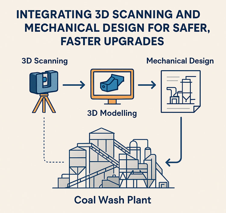
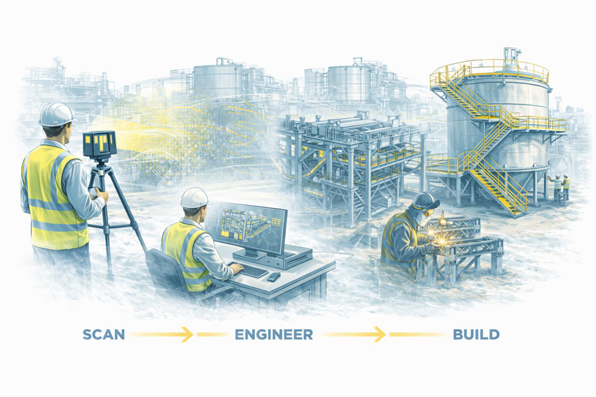
The Role of Modern Engineering Tools (Briefly)

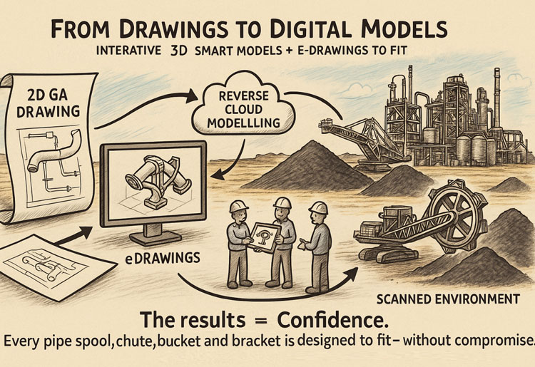
While AS 3774 is fundamentally about load determination, modern engineering tools can support compliance by helping teams:

  • Verify as-built geometry against design assumptions
  • Identify eccentric discharge paths and flow constraints
  • Review interfaces, wall angles, and structural continuity
  • Support independent engineering assessment without extended shutdowns

These tools do not replace the standard โ€” but they can help reveal whether its principles have been properly applied.


What Asset Owners and Project Managers Should Ask For

To demonstrate that AS 3774 has been adequately considered, asset owners and project managers should expect to see clear answers to questions such as:

  • What load cases were considered under AS 3774?
  • How were discharge conditions defined and assessed?
  • What assumptions were made about material properties?
  • How were eccentric and asymmetric loads addressed?
  • Was fatigue or cyclic loading considered?
  • How were mixed materials and interfaces assessed?
  • Has an independent engineering review been undertaken?

If this information cannot be clearly provided, compliance is difficult to demonstrate, regardless of how new the installation is.


Hamilton By Design logo displayed on a blue tilted rectangle with a grey gradient background

Why This Matters for New Installations

AS 3774 compliance is not about legacy assets or historical practices.
It is about ensuring that new installations are fit for purpose, safe, and defensible.

Where bulk solids containers are being delivered today without adequate consideration of realistic load behaviour, the risk is being transferred downstream โ€” to operators, maintainers, and asset owners.


Our clients


A Practical Closing Thought

If you are unsure whether AS 3774 has been properly applied to a bulk solids container, an independent engineering review can provide clarity.

The cost of verifying load assumptions and structural adequacy is typically minor compared to the consequences of discovering load-related issues after commissioning.

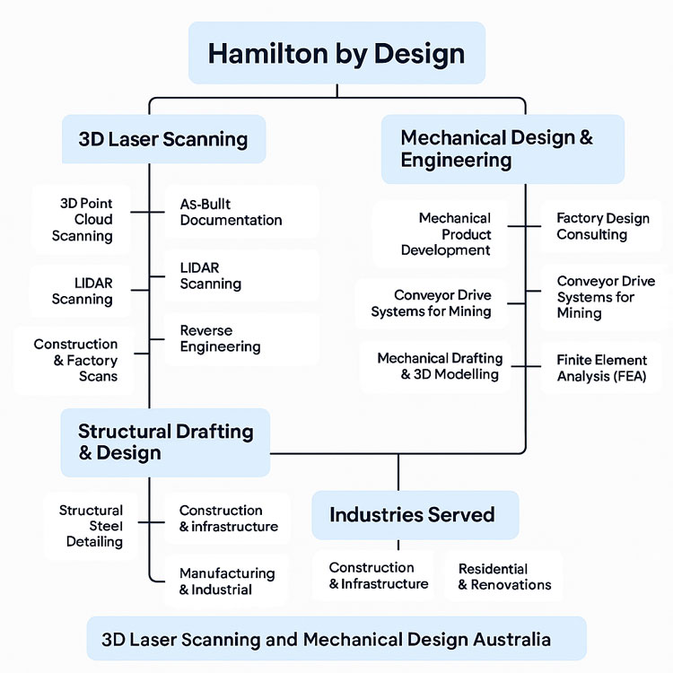
Hamilton By Design supports asset owners and project teams with engineering review, verification, and redesign of bulk solids containers, helping ensure that safety and compliance are addressed before problems develop.

Name
Would you like us to arrange a phone consultation for you?
Address

AS 1755 Conveyor Safety

Engineer reviewing a guarded conveyor system with fixed side and nip-point guards designed to prevent access to moving parts.

Designing Conveyor Guarding for Compliance, Safety, and Practical Operation

Conveyors are widely used across processing, manufacturing, and materials-handling environments, but they also present some of the most persistent safety risks in industrial operations. Entrapment, nip points, rotating components, and maintenance access are all recognised hazards that must be managed through proper design and guarding.

In Australia, these risks are addressed through AS 1755 โ€“ Conveyors โ€“ Safety Requirements, which establishes the minimum safety expectations for conveyor systems across their full lifecycle, from design and installation through to operation and maintenance.

This article outlines what AS 1755 requires, why compliant conveyor guarding is critical, and how engineering-led design plays a key role in achieving practical safety outcomes.


Bulk materials conveyor with compliant safety guarding at the hopper, tail end, and along the conveyor, shown with an engineer reviewing guarding design drawings.

What Is AS 1755?

AS 1755 is the Australian Standard that defines safety requirements for belt conveyors and other conveyor systems. It addresses both new and existing installations and applies to conveyors used in industrial, commercial, and processing environments.

Rather than focusing on individual guarding components in isolation, AS 1755 considers the conveyor system as a whole, including how people interact with it during normal operation, inspection, cleaning, and maintenance.

The standard is referenced by regulators, safety professionals, and engineers as the primary benchmark for conveyor safety in Australia.


Key Safety Principles in AS 1755

AS 1755 is built around a number of core safety principles that influence how conveyor guarding should be designed.

These include eliminating hazards where possible, controlling remaining risks through engineering solutions, and ensuring that guarding does not introduce new risks by restricting access or encouraging unsafe behaviour.

In practice, this means that compliant guarding must be effective, durable, and suitable for the operating environment, while still allowing conveyors to be inspected, cleaned, and maintained safely.


Conveyor Guarding Requirements

A major focus of AS 1755 is the control of access to hazardous areas. This includes guarding of:

  • Drive pulleys and tail pulleys
  • Return rollers and idlers
  • Nip points and shear points
  • Rotating shafts and couplings
  • Chain drives, belt drives, and gearboxes

Guarding must be designed so that body parts cannot access hazardous zones, taking into account reach distances, openings, and the position of the conveyor relative to walkways or platforms.

Importantly, AS 1755 recognises that guarding must be fit for purpose. Poorly designed guards that are difficult to remove, inspect, or maintain are often bypassed or removed altogether, creating new safety risks.


Fixed Guards vs Interlocked Guards

AS 1755 allows for different types of guarding depending on the application and risk profile.

Fixed guards are commonly used where access is not required during normal operation. These guards must be securely fixed and require tools for removal.

Interlocked guards may be required where regular access is necessary. These systems ensure that the conveyor cannot operate while the guard is open or removed, reducing the risk of exposure to moving parts.

Selecting the appropriate guarding strategy requires an understanding of how the conveyor is used in practice, not just how it appears on drawings.


Existing Conveyors and Retrofit Challenges

Many conveyors currently in service were installed before the latest versions of AS 1755 were adopted. In these cases, compliance is often achieved through retrofit guarding rather than full replacement.

Retrofitting guarding to existing conveyors introduces additional challenges, including:

  • Limited space around existing equipment
  • Incomplete or outdated drawings
  • Structural constraints
  • Ongoing operation during upgrades

Engineering-led assessment and accurate documentation of existing conditions are critical when designing retrofit guarding solutions that comply with AS 1755 without disrupting operations.


The Role of Engineering in Conveyor Guarding Design

AS 1755 does not provide prescriptive โ€œone-size-fits-allโ€ guard designs. Instead, it sets performance requirements that must be interpreted and applied by competent professionals.

Engineering input is essential to ensure that conveyor guarding:

  • Addresses all relevant hazards
  • Integrates with existing mechanical and structural systems
  • Can be fabricated and installed accurately
  • Supports safe maintenance and inspection activities

Poorly engineered guarding may appear compliant on paper but fail in real-world use.


Documentation, Verification, and Ongoing Safety

Compliance with AS 1755 is not a one-time activity. Conveyor systems evolve over time as layouts change, equipment is upgraded, and operating practices shift.

Clear documentation of guarding design, installation, and assumptions provides a baseline for future modifications and safety reviews. This documentation is also critical when demonstrating due diligence to regulators or during incident investigations.


Why AS 1755 Matters

AS 1755 exists to prevent serious injuries and fatalities associated with conveyor systems. When applied correctly, it provides a structured framework for identifying hazards, implementing effective controls, and maintaining safe operation over the life of the equipment.

Achieving compliance requires more than installing mesh around moving parts. It requires understanding how people interact with conveyors and designing guarding that supports safe behaviour rather than working against it.


Hamilton By Design logo displayed on a blue tilted rectangle with a grey gradient background

Conveyor guarding designed in accordance with AS 1755 is a critical component of safe industrial operations. Engineering-led design, accurate documentation, and practical consideration of maintenance and operation are essential to achieving compliance that works in practice.

When conveyor safety is treated as an engineering problem rather than a checkbox exercise, the result is safer equipment, fewer incidents, and more reliable operations.

Manufacturing and production services button

Our clients


Name
Would you like us to arrange a phone consultation for you?
Address

SolidWorks Mechanical Design Services

Hero image showing a LiDAR-coloured point-cloud model of an industrial conveyor system on the left transitioning into a detailed SolidWorks 3D CAD model on the right, with the heading โ€˜SolidWorks Mechanical Design Servicesโ€™ and a call-to-action button that reads โ€˜Start Your Projectโ€™

SolidWorks Design Services

The Many Faces of Mechanical Design: How SolidWorks Powers Modern Engineering Across Australia

At Hamilton By Design, we see the same pattern every day across mining, heavy industry, manufacturing, and complex brownfield environments: the quality of engineering outcomes depends directly on the quality of the models driving them. And when it comes to mechanical design, SolidWorks remains one of the most capable and versatile platforms on the planet.

From dragline components to sheet metal enclosures, from pressure vessel upgrades to bespoke robotics, SolidWorks enables engineers to turn ideas into precise, fabrication-ready models that reduce rework, eliminate uncertainty, and accelerate project delivery.

Below, we explore the full spectrum of mechanical design disciplines where SolidWorks excels โ€” and how Hamilton By Design uses this capability to deliver accurate, reliable, engineering-grade outcomes across Australia.


Why SolidWorks Remains the Backbone of Mechanical Design

SolidWorks brings together parametric modelling, simulation, large assembly performance, surfacing, sheet metal tools, weldments, routing and visualisation under a single environment. The result is powerful:

โœ” Engineering that is data-driven
โœ” Models that are precise and fabrication-ready
โœ” Assemblies that reflect true site conditions
โœ” Designs that respond intelligently to changes
โœ” Drawings that follow Australian Standards
โœ” Seamless integration with LiDAR-based as-builts

When paired with Hamilton By Designโ€™s LiDAR scanning workflows, SolidWorks becomes an engine for delivering zero-guesswork mechanical design.


Mechanical Design Disciplines Perfectly Suited to SolidWorks Modelling

SolidWorks supports a huge range of engineering tasks. Below is a deep dive into the disciplines where Hamilton By Design deploys it every day.


1. Machine Design: Precision for Moving Systems

SolidWorks is a natural fit for mechanical equipment upgrades and R&D design work, including:

  • Gearboxes, shafts, keys, couplings
  • Linear motion systems and actuators
  • Mechanical linkages, cams and levers
  • Robotic mechanisms
  • Safety guards, enclosures and subframes
  • Automation concept development

Whether weโ€™re modelling a drive assembly for a conveyor or designing a new piece of automated equipment, SolidWorks gives us full control over the mechanics, kinematics, clearances and manufacturability.


2. Structural Mechanical Design: Frames, Platforms & Fabrication

Mining and industrial plants rely heavily on welded structures and access systems. SolidWorks weldments excel at:

  • Platforms, walkways and stair systems
  • Equipment bases, skids and structural frames
  • Gantries, monorails and supports
  • Pipe supports and brackets
  • Structural reinforcements and upgrade scopes

Built-in cut lists, profile libraries and FEA ensure every frame is practical, safe and fabrication-ready.


3. Pressure Vessels, Tanks & Piping Systems

SolidWorks is an ideal tool for pressure-bound components and interconnected plant systems:

  • Tanks, vessels, bins and hoppers
  • Nozzles, flanges, stiffeners and ladders
  • Pipe routing and spooled sections
  • Chute systems, transitions and flow paths
  • Wear liners and maintenance-friendly redesigns

With stress linearisation, buckling analysis and accurate geometry import from LiDAR scans, we ensure designs meet engineering intent and fit up perfectly on site.


4. Sheet Metal: From Light Fabrication to Industrial Ducting

SolidWorks is the industry standard for sheet metal components:

  • Ducting and HVAC transitions
  • Guards, housings and folded enclosures
  • Electrical cabinets
  • Chute panels
  • Laser-cut and folded brackets

Automatic flat patterns and K-factor control mean fewer mistakes at the plasma/laser cutters and more predictable outcomes for fabricators.


5. Heavy Industry & Mining Equipment Modelling

Hamilton By Designโ€™s roots in mining and heavy industry make SolidWorks invaluable for:

  • Conveyor components and guarding
  • Diverter chutes, hoppers and flow-optimised transitions
  • Bucket-wheel reclaimer parts
  • Crusher and screen upgrades
  • Dragline component modelling
  • Structural deformation/realignment scopes

Combined with LiDAR scanning, SolidWorks becomes the tool that eliminates shutdown fit-up problems.


6. Product Design & Industrial Design

SolidWorksโ€™ surfacing and parametric tools are ideal for:

  • Consumer products
  • Power tools and ergonomic items
  • Injection-moulded components
  • Kitchen or appliance prototypes
  • Concept development for early-stage R&D

It supports rapid iterations, rendering, and export for 3D printing.


7. Robotics & Automation Systems

With the rise of automated processing and Industry 4.0, SolidWorks continues to shine in:

  • End effectors
  • Robotic arms and actuators
  • Kinematic studies
  • Sensor housings
  • Concept layouts for automated cells

We frequently pair this with our LiDAR models of existing plants to create automation solutions that genuinely fit the space.


8. Tooling, Jigs & Fixtures

Fabrication and machining rely on accurate tooling, and SolidWorks helps us design:

  • Welding jigs
  • Machining fixtures
  • Assembly tooling
  • Positioning and inspection gauges
  • Drill guides and alignment tooling

Parametric updates make future modifications simple and consistent.


9. Material Handling Systems

Across mining, ports, agriculture and waste facilities, SolidWorks supports:

  • Conveyor layouts
  • Screw and chain conveyors
  • Transfer chute redesigns
  • Feeders, bins and flow systems
  • Skids and support structures

We routinely pair mechanical redesign with simulation, checking wear patterns, stresses and clearances.


10. Reverse Engineering & As-Built Modelling from LiDAR

This is where Hamilton By Design leads the industry.

We scan sites with millimetre-level LiDAR, then rebuild clean parametric models in SolidWorks for:

  • Brownfield upgrades
  • Fit-up verification
  • Clash detection
  • Replacements and like-for-like manufacturing
  • Structural deformation assessments
  • Shutdown planning

It is the combination of LiDAR + engineering + SolidWorks that gives clients complete confidence in their next project.


How Clients Benefit from SolidWorks-Driven Mechanical Design

โœ” Reduced rework

โœ” Faster shutdown upgrades

โœ” Accurate manufacturing drawings

โœ” Better communication between engineers, fabricators and site teams

โœ” Safer and more predictable installations

โœ” Clear, simulation-backed decision-making

From CHPPs to ports, from power stations to manufacturing plants, SolidWorks modelling allows Hamilton By Design to deliver engineering outcomes you can trust.


Hamilton By Design logo displayed on a blue tilted rectangle with a grey gradient background

Partner With Hamilton By Design for SolidWorks Mechanical Design

We support clients across:

  • NSW (Sydney, Newcastle, Central Coast, Hunter Valley)
  • QLD (Bowen Basin, Surat Basin, Mount Isa)
  • WA (Perth, Pilbara)
  • SA, VIC and regional Australia

If your next project needs mechanical accuracy, design certainty or LiDAR-integrated engineering, our team is ready to support you.

Name
Address
You would like to:

Our clients

SolidWorks

3D Laser Scanning

Engineering Projects

Engineering Services

3D Laser Scanning for Engineering

3D Scanning for Industrial Projects in Newcastle and the Hunter Valley

Engineering the Hunter: Precision Meets Industry

Few regions in Australia represent heavy industry quite like Newcastle and the Hunter Valley.
From the coal mines at Bengalla and Mount Thorley, to the power stations at Bayswater and Eraring, to the Port of Newcastleโ€™s massive shiploaders and conveyors, this region has powered Australia for generations.

But with age, complexity, and constant upgrades come challenges:

  • Outdated drawings
  • Tight shutdown schedules
  • Complex brownfield modifications
  • Difficult site access

Thatโ€™s where 3D scanning and LiDAR modelling are transforming how industrial projects are designed, verified, and delivered โ€” ensuring every bolt, beam, and bracket fits perfectly the first time.

At Hamilton By Design, we bring together field experience, digital precision, and local knowledge to help the Hunterโ€™s industries design, maintain, and modernise with confidence.


Technician operating a FARO 3D laser scanner inside an industrial plant to capture accurate geometry for brownfield upgrades, shown alongside Hamilton By Design and 3DEXPERIENCE logos with highlighted challenges such as outdated drawings and tight shutdown schedules

What Is 3D Scanning โ€” and Why It Matters in Industry

3D laser scanning, also known as LiDAR (Light Detection and Ranging), captures millions of data points across an industrial site to create a precise digital representation โ€” known as a point cloud.

This point cloud forms the foundation of a digital twin of your plant or asset โ€” an exact, measurable 3D environment that engineers can design within using SolidWorks, AutoCAD, or Navisworks.

The result?
Every measurement is accurate, every clash is detected before fabrication, and every installation happens exactly as planned.


Why Newcastle and the Hunter Valley Need Scanning More Than Ever

The Hunter is an engineering powerhouse โ€” but much of its infrastructure was built decades ago.
Many coal handling plants, power stations, and smelters are now in a constant cycle of refurbishment, retrofit, and compliance upgrade.

The challenges are familiar:

  • Old 2D drawings donโ€™t reflect todayโ€™s reality.
  • Assets have been modified repeatedly over decades.
  • Shutdown windows are shrinking.
  • Every error adds cost and delays production.

By scanning before you design, you remove uncertainty.
You donโ€™t guess clearances โ€” you know them.
You donโ€™t estimate tie-in points โ€” you model them.
You donโ€™t hope it fits โ€” you prove it digitally.

Thatโ€™s the power of 3D scanning in todayโ€™s industrial environment.


FARO 3D laser scanner set up on a tripod capturing an industrial plant for LiDAR scanning and digital modelling, with Hamilton By Design branding in the corner

Where Scanning Adds Value Across the Hunterโ€™s Industries

โš™๏ธ Power Generation

The Bayswater, Eraring, and Vales Point Power Stations are engineering icons.
Upgrades to cooling systems, ducts, platforms, and access structures require millimetre accuracy.
3D scanning ensures:

  • Every retrofit aligns with existing steelwork and pipework.
  • Structural interferences are caught before fabrication.
  • Shutdown work can be completed on time โ€” without rework.

Whether itโ€™s a fan casing replacement or a duct reroute, laser scanning removes the guesswork from aging assets.


โ›๏ธ Coal Handling and CHPP Facilities

The Hunter Valleyโ€™s CHPP network โ€” Mount Thorley Warkworth, Ravensworth, Bengalla, Hunter Valley Operations โ€” all depend on reliable mechanical systems.
These plants evolve continuously: diverter chutes, screen replacements, conveyors, and wash plant modifications.

Scanning delivers:

  • Accurate as-built geometry for plant upgrades.
  • Clash detection between new and existing equipment.
  • Shutdown planning certainty โ€” no unexpected fit-up issues.
  • Integration of SolidWorks models directly into point clouds for visual verification.

For CHPP managers and maintenance engineers, 3D scanning is now as essential as the plant itself.

Composite image showing an Australian Standard compliance graphic, a LiDAR point-cloud scan of a coal reclaimer with inspection markers, and the Hamilton By Design logo

โš“ Port of Newcastle and Coal Export Terminals

Newcastleโ€™s port is the lifeline of the Hunterโ€™s economy.
Facilities such as Port Waratah Coal Services (PWCS), Newcastle Coal Infrastructure Group (NCIG), and Carrington Terminal handle massive volumes of coal every hour.

The complexity of these sites โ€” shiploaders, conveyors, gantries, and stacker-reclaimers โ€” demands accuracy during maintenance and upgrade works.
3D scanning supports:

  • Shiploader upgrades and boom extensions.
  • Conveyor and transfer tower alignment checks.
  • Wharf structure condition monitoring.
  • Integration with mechanical and electrical systems.

By scanning before modification, downtime is reduced, safety improves, and project teams gain total confidence in every fit-up.


๐Ÿญ Aluminium and Heavy Manufacturing

At Tomago Aluminium Smelter, precision is everything.
The scale of the site โ€” from potlines to switchyards โ€” makes manual measurement impractical and unsafe.

Laser scanning captures geometry accurately across large areas, enabling:

  • Retrofit planning without full shutdowns.
  • Clearance checks for cranes, ducts, and potline infrastructure.
  • Digital twins for long-term maintenance and asset management.

Beyond Tomago, manufacturers in Waratah, Beresfield, and Thornton use scanning to validate jigs, fixtures, and workshop layouts โ€” ensuring local fabrication accuracy that matches site requirements.


๐Ÿ”‹ Emerging Energy and Infrastructure

As the Hunter region transitions toward renewable and low-emission industries, scanning plays a critical role in planning new infrastructure around existing sites.
This includes:

  • Hydrogen and gas pipeline tie-ins.
  • Solar and battery installations near existing grid connections.
  • Conversion of existing power plant structures for new technology.

Accurate point-cloud data ensures new energy meets old infrastructure safely and efficiently.


From Field to Fabrication: The Hamilton By Design Process

At Hamilton By Design, our 3D scanning workflow is built around practical, industrial needs:

  1. Site Scan & Data Capture
    Using high-precision LiDAR scanners, we safely capture full site geometry in hours, not weeks.
    Scans are performed during operation or short shutdowns, without interrupting production.
  2. Point Cloud Registration & Processing
    Multiple scans are aligned to create a unified, accurate model of your facility.
    The result is a true โ€œdigital twinโ€ of your asset, complete with millimetre accuracy.
  3. SolidWorks Modelling & Integration
    Our design team converts scan data into fully functional 3D models โ€” chutes, pipework, platforms, or structural frames โ€” ready for fabrication.
  4. Clash Detection & Design Validation
    Every new design is tested within the digital twin, ensuring it fits the first time.
  5. Fabrication Drawings & e-Drawings
    Detailed 2D and 3D deliverables are provided for fabricators, site crews, and certifiers โ€” ensuring seamless communication between design and construction.

Why Local Expertise Matters

Many engineering firms offer scanning โ€” but few understand what it takes to work on a live plant in the Hunter Valley.

Hamilton By Design combines trade experience, mechanical design, and regional understanding.
Weโ€™ve worked with the same assets, fabricators, and contractors who keep the regionโ€™s power, port, and manufacturing industries running.

We design for real fabrication conditions โ€” using Australian Standards, local materials, and practical build methods.
That means fewer redesigns, faster turnarounds, and safer installations.


Safety and Access: Scanning Without Shutdowns

Traditional site measurement often means working at heights, in confined spaces, or around operating equipment.
3D scanning eliminates those risks.

Our scanners capture data safely from the ground โ€” even in restricted or hazardous areas.
This not only improves safety but also allows projects to continue without halting production.

For large plants like Eraring or PWCS, scanning entire structures during live operation is now standard practice โ€” enabling ongoing maintenance and long-term asset integrity planning.


Case Example: Port Upgrade Without Rework

A local contractor approached Hamilton By Design for a conveyor and tower modification project at the Port of Newcastle.
Existing drawings were decades old, and the structure had been modified repeatedly.

We performed a 3D scan of the tower and adjacent conveyors, capturing the as-built geometry in one day.
The resulting model revealed several misalignments between the planned chute and existing supports.
By correcting these in SolidWorks before fabrication, the contractor avoided at least 48 hours of site rework and kept the shutdown on schedule.

Thatโ€™s measurable ROI โ€” precision that pays for itself.


The ROI of 3D Scanning in Heavy Industry

A single hour of lost production at a CHPP or power station can cost $20,000 to $50,000.
A single dayโ€™s delay can exceed $500,000 in lost revenue and labour costs.

3D scanning reduces that risk by eliminating rework and ensuring every component fits right the first time.
Typical return on investment (ROI):

  • Scanning cost: <1% of total project value.
  • Rework savings: 3โ€“10% of total cost.
  • Downtime reduction: 1โ€“3 days saved per shutdown.

When accuracy drives reliability, 3D scanning isnโ€™t an expense โ€” itโ€™s insurance.


Supporting the Hunterโ€™s Future

Newcastle and the Hunter Valley are evolving โ€” from coal and power to renewables, advanced manufacturing, and logistics.
But one thing hasnโ€™t changed: the regionโ€™s foundation in engineering, precision, and hard work.

Hamilton By Design supports that legacy with the next generation of technology โ€” scanning, digital modelling, and mechanical design that keep the regionโ€™s assets efficient, safe, and ready for the future.

Weโ€™re not an offshore CAD vendor.
Weโ€™re local engineers whoโ€™ve worked in the field, understand your equipment, and speak the same language as your crews.


Letโ€™s Build the Future of Hunter Industry โ€“ Accurately

Every project starts with one question: โ€œDo we have accurate site data?โ€

With Hamilton By Design, the answer is always yes.

We deliver:
โœ… 3D laser scanning and LiDAR modelling
โœ… Point-cloud to SolidWorks integration
โœ… Reverse engineering and FEA validation
โœ… Fabrication drawings tailored for local workshops
โœ… On-site consultation with practical engineering insight

Whether youโ€™re upgrading a conveyor at Bayswater, fabricating platforms for Tomago, or retrofitting process piping at Kooragang, we ensure your next project fits perfectly โ€” before steel is cut.

Banner displaying Hamilton By Design alongside partner and technology logos including SolidWorks, UTS, Dassault Systรจmes 3DEXPERIENCE, and FARO, with the text โ€˜3D Scanning 3D Modellingโ€™ and website www.hamiltonbydesign.com.au.

๐Ÿ‘‰ Get your industrial site scanned and modelled before your next shutdown.
Visit www.hamiltonbydesign.com.au or contact us to request a capability statement today.

Mechanical Engineering | Structural Engineering

Mechanical Drafting | Structural Drafting

3D CAD Modelling | 3D Scanning

Hamilton By Design logo displayed on a blue tilted rectangle with a grey gradient background

Our clients;

Name
Would you like us to arrange a phone consultation for you?
Address

Integrating 3D Scanning and Mechanical Design for Safer, Faster Upgrades in Coal Wash Plants

Precision Without the Guesswork

Upgrading or maintaining a coal wash plant has always been a challenge โ€” tight shutdown windows, complex layouts, and the need for perfect fit-ups between new and existing components. Traditional measurement methods, like tape measures and manual sketches, are often impossible in restricted or hazardous areas.

Thatโ€™s where 3D scanning and mechanical engineering come together. At Hamilton By Design, we combine precision laser scanning, intelligent 3D modelling, and practical mechanical design to deliver risk-free upgrades โ€” ensuring every component fits right the first time.

Infographic showing how 3D scanning and 3D modelling feed into mechanical design for safer, faster upgrades at a coal wash plant, with icons representing scanning, modelling, and engineering drawings

When Accuracy Matters Most

Coal wash plants are intricate systems. From cyclones, screens, and diverter chutes to pumps, piping, and structures, every part interacts under tight tolerances. A small misalignment can lead to vibration, spillage, or shutdown delays.

Our 3D scanning process captures millions of spatial data points, creating a detailed digital twin of the existing plant. This allows us to model upgrades, design replacement components, and simulate fit-up โ€” all before fabrication begins.

In many cases, scanning replaces the need to physically measure equipment. For example, in confined or high-risk spaces where a tape measure simply canโ€™t reach, scanning provides complete, line-of-sight geometry with millimetre accuracy.

Recently, our team scanned a diverter chute that had been incorrectly installed. The resulting model revealed that the chute had been fitted in the wrong orientation โ€” explaining why it wasnโ€™t sealing properly. This insight helped our client avoid further downtime and costly rework.


Combining Engineering Experience with Digital Precision

Hamilton By Design provides a full suite of mechanical engineering services tailored to the mining industry, including:

  • 3D Scanning & Point Cloud Capture โ€“ detailed mapping of existing equipment and structures
  • 3D Modelling & Reverse Engineering โ€“ accurate, editable digital models
  • Mechanical Design & Structural Replacement โ€“ like-for-like component upgrades
  • Piping Routes & Spool Fabrication โ€“ optimised pipe design and layout
  • Fabrication & Component Drawings โ€“ compliant with Australian Standards and client templates

Our engineers work across SolidWorks, AutoCAD Plant 3D, Revit, and 3D Experience platforms โ€” integrating point cloud data directly into the design workflow. This means fewer site visits, fewer surprises, and significantly less rework once fabrication begins.


From Drawings to Digital Models

Weโ€™ve evolved beyond traditional 2D general arrangement drawings. Instead, we provide interactive 3D models and e-drawings that allow clients, fabricators, and site teams to visualise how upgrades will fit within the plant.

Our reverse cloud modelling process inserts 3D designs directly into the scanned environment. This enables engineers and site teams to measure potential interferences, check clearances, and validate installation methods โ€” long before shutdowns begin.

Illustrated workflow showing how 2D GA drawings and scanned environments are turned into 3D digital models through reverse cloud modelling and eDrawings, demonstrating confidence in fabrication fit for mining and industrial equipment.

The result = Confidence.
Every pipe spool, chute, and bracket is designed to fit โ€” without compromise.


Supporting Contractors and Plant Operators

We partner with:

  • Mining companies operating coal wash plants
  • Fabricators and contractors supplying mining equipment
  • Maintenance providers planning plant shutdowns

Their biggest challenge is finding people who design for fit and function โ€” not just form. Not all CAD or point cloud software is equal, and not every designer understands the realities of on-site installation. Thatโ€™s where Hamilton By Design stands apart.

We bring hands-on mechanical trade experience, engineering design expertise, and digital technology together โ€” helping your team deliver upgrades that work, first time.


Built to Australian Standards

All design and drawing deliverables are completed in accordance with Australian Standards, ensuring compliance, safety, and interoperability with existing documentation.

We can also supply fabrication drawings on client-specific templates, maintaining intellectual property (IP) requirements and formatting standards.


Servicing Australiaโ€™s Key Mining Regions

Hamilton By Design proudly supports coal wash plant upgrades and mechanical design projects across Australiaโ€™s leading coal regions, including:

  • Bowen Basin
  • Surat Basin
  • Hunter Valley
  • Newcastle
  • Central Coast
  • Western and Central NSW coalfields

Our local experience ensures that we understand the logistical, operational, and environmental challenges unique to each region โ€” helping projects stay compliant, efficient, and on schedule.


Why Choose Hamilton By Design?

  • Reduced Downtime: Accurate pre-shutdown planning through digital models.
  • Improved Safety: Less manual measuring in hazardous or confined areas.
  • Guaranteed Fit-Up: Fabrication drawings verified against real-world geometry.
  • Faster Turnaround: Streamlined scanning-to-design-to-fabrication workflow.
  • Proven Experience: Over two decades in mechanical engineering and plant design.

Our mission is simple โ€” to take the risk out of upgrades by combining engineering insight with digital accuracy.


Quote

โ€œPrecision scanning and mechanical design โ€” taking the risk out of plant upgrades.โ€


Letโ€™s Make Your Next Upgrade Risk-Free

If your next shutdown involves mechanical upgrades, pipework replacement, or structural modifications, talk to Hamilton By Design.

We can help you visualise, plan, and execute upgrades with confidence โ€” reducing downtime, eliminating measurement errors, and delivering safer outcomes for your team.

info@hamiltonbydesign.com.au
www.hamiltonbydesign.com.au

Mechanical Drafting | Structural Drafting

3D CAD Modelling | 3D Scanning

Chute Design

Our clients:

Name
Would you like us to arrange a phone consultation for you?
Address

Hamilton by Design: Your Experts in 3D Laser Scanning & Mechanical Design

Engineer-led 3D laser scanning of an industrial plant transitioning into mechanical engineering design and steel fabrication.

When it comes to precision engineering, structural drafting, and mechanical design services, Hamilton by Design leads the way. We provide advanced 3D laser scanning solutions across Perth, Sydney, Brisbane, Melbourne, and the Hunter Valley โ€” giving clients accurate data for smarter decisions and efficient project delivery.

Hamilton by Design services diagram showing four key areas: 3D Laser Scanning, Mechanical Design and Engineering, Structural Drafting and Design, and Industries Served. The chart lists services such as 3D point cloud scanning, as-built documentation, reverse engineering, mechanical product development, conveyor drive systems for mining, factory design consulting, FEA, structural steel detailing, and design for construction, manufacturing and industrial sectors. Industries served include construction and infrastructure, and residential and renovations. A footer reads โ€˜3D Laser Scanning and Mechanical Design Australia

3D Laser Scanning Across Australia

Our 3D laser scanning services capture exact measurements of your site, plant, or equipment to create detailed 3D point clouds and as-built documentation. This reduces rework, saves time, and improves project planning.

We offer:

  • 3D Laser Scanning Perth & Fremantle โ€“ Industrial plant surveys, mining site scanning, and reverse engineering.
  • 3D Laser Scanning Sydney & Melbourne โ€“ Building surveys, renovation planning, and structural inspections.
  • 3D Laser Scanning Brisbane & Hunter Valley โ€“ Factory layouts, conveyor drive design, and structural scanning.
  • 3D Laser Scanning for Engineering & Mining โ€“ Point cloud scanning, clash detection, and 3D modelling.

Our team uses the latest 3D scanning and LiDAR technology to produce millimetre-accurate results that engineers, architects, and builders can trust.

Structural Drafting & Design Services

Hamilton by Design provides structural drafting services across Australia, including:

  • Structural Design and Drafting โ€“ For residential, commercial, and industrial projects.
  • Steel Detailing & Shop Drawings โ€“ Produced to Australian drafting standards.
  • Structural Scanning Services Brisbane & Sydney โ€“ Helping engineers assess existing structures for upgrades or repairs.

Our experienced structural design engineers work closely with builders, architects, and civil engineers in Hamilton and beyond to deliver reliable, build-ready plans.

Engineer using 3D LiDAR scanning to capture an industrial facility, followed by CAD modelling and fabrication-ready steelwork.

See Structural Engineering for more info

Mechanical Design & Engineering Solutions

We are a full-service mechanical design consultancy offering:

  • Mechanical Product Design & Development
  • Factory & Plant Layout Design
  • Conveyor Belt Drive Systems & Mining Equipment Design
  • Finite Element Analysis (FEA) and performance validation
  • Reverse Engineering Services Perth for spare parts and retrofits

Our team of mechanical engineers, drafters, and CAD designers ensures every project is efficient, safe, and cost-effective.

see Mechanical Engineering for more info

Industries We Serve

Hamilton by Design supports clients across:

  • Mining & Resources โ€“ Coal conveyors, feed thickeners, and vibrating equipment in Kalgoorlie and Mount Isa.
  • Construction & Infrastructure โ€“ As-built scanning and 3D modelling for building projects.
  • Manufacturing โ€“ Factory optimization and equipment design.
  • Residential Projects โ€“ Drafting services for home renovations and new builds in Hamilton and surrounding areas.

Why Partner with Hamilton by Design?

Choosing Hamilton by Design means working with mechanical design experts and structural drafters who are committed to accuracy, speed, and innovation.

Infographic showing 3D laser scanning capturing industrial equipment to identify challenges such as vibration, movement, and fluid leaks, feeding into a 3D model that improves planning, reduces rework, and supports safer maintenance

Australia-Wide Coverage โ€“ Perth, Sydney, Melbourne, Brisbane, Hunter Valley
Cutting-Edge Technology โ€“ Laser scanning, CAD modelling, and 3D visualization
Expert Team โ€“ Experienced mechanical engineers and design consultants
Cost-Effective Solutions โ€“ Saving time, reducing errors, and minimizing rework


Get Started Today

Ready to transform your next project with 3D laser scanning, structural drafting, or mechanical design services?

Contact Hamilton by Design for a consultation and see how our team can deliver precise, efficient, and innovative solutions for your business.


Hamilton By Design logo displayed on a blue tilted rectangle with a grey gradient background

Name
Would you like us to arrange a phone consultation for you?
Address

Hamilton By Design โ€“ Blog

Consulting Engineers

About Us โ€“ Hamilton By Design

Contact us