Industrial Engineering Alexandria & Rosebery | HBD

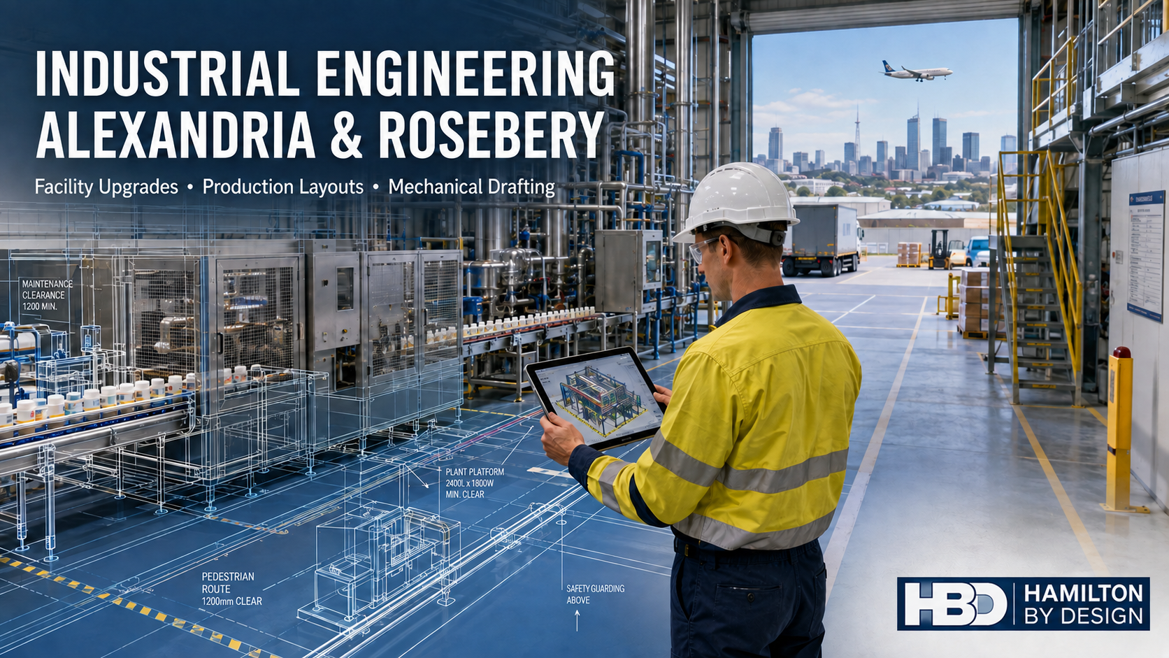
Industrial engineering in Alexandria and Rosebery showing an engineer reviewing a factory CAD model, with production equipment and the Hamilton By Design logo.

Industrial Engineering Support for Alexandria and Rosebery Facilities

Blue 3D LiDAR scanner icon on a tripod with scanning waves

Alexandria and Rosebery form an important commercial and industrial precinct within inner-southern Sydney. Their proximity to Sydney Airport, Port Botany, the Sydney CBD and the WestConnex motorway network supports a diverse combination of manufacturing, food and beverage businesses, warehousing, freight forwarding, equipment maintenance, automotive services, technical companies and adaptive-reuse developments.

Although the area continues to change, many properties retain their original industrial character. Former factories, workshops and warehouses are being modified to accommodate new production processes, logistics operations, commercial kitchens, technical workplaces and mixed commercial-industrial uses.

These changes can create difficult engineering questions. Existing drawings may be incomplete, plant and services may have been modified over several decades, and new equipment must often be installed within restricted spaces while the facility remains operational.

Hamilton By Design provides engineering services across Sydney to help asset owners, manufacturers, facilities managers, contractors and project teams plan practical modifications to existing industrial properties.

The work may combine existing-condition documentation, mechanical engineering, production-layout development, risk assessment, CAD modelling, mechanical drafting and fabrication support. The objective is to establish reliable project information and convert it into documentation that can be used for design, approval, procurement, fabrication and installation.

An Evolving Inner-Sydney Industrial Area

Alexandria has a strong history of manufacturing, warehousing and urban services. Today, the area contains a mixture of traditional workshops, multi-tenant industrial estates, distribution facilities, showrooms, food businesses, equipment suppliers, automotive operations and technical workplaces.

Rosebery has undergone substantial redevelopment, but its industrial history remains visible in former factories, warehouses and workshops that have been converted for new commercial purposes. The suburb now accommodates food and hospitality businesses, commercial kitchens, retail production, creative enterprises, offices and mixed-use developments alongside remaining industrial operations.

This combination makes the Alexandriaโ€“Rosebery area different from a new industrial estate. New equipment and fit-outs frequently need to be integrated into existing buildings that were designed for a different process or occupancy.

A successful project must therefore consider more than whether the proposed equipment fits on a floor plan. It may also need to address:

  • Existing structural columns and roof framing
  • Congested mechanical and electrical services
  • Production and warehouse operations
  • Vehicle and pedestrian movements
  • Loading and delivery access
  • Equipment cleaning and maintenance requirements
  • Emergency access and egress
  • Noise, ventilation and exhaust arrangements
  • Fire-service interfaces
  • Installation and lifting constraints
  • Applicable Australian Standards
  • Future changes to the facility

An engineering-led assessment can help bring these considerations together before detailed design or construction begins.

The Problem of Incomplete Existing Information

Reliable engineering begins with an understanding of existing conditions. However, older industrial buildings frequently have several different sets of drawings.

An original architectural drawing may show the building as it was first proposed. A later tenancy plan may show new walls but omit mechanical equipment. Services drawings may be incomplete, while modifications undertaken during maintenance work may never have been added to the controlled drawing set.

As a result, project teams can encounter discrepancies involving:

  • Wall, column and door locations
  • Floor levels and roof heights
  • Pipework and duct routes
  • Mechanical plant positions
  • Equipment foundations
  • Platforms and mezzanines
  • Fire and electrical services
  • Loading-dock geometry
  • Storage areas and racking
  • Access and maintenance clearances

These discrepancies may initially appear minor, but they can become costly when fabricated components must connect to an existing asset.

Hamilton By Design can assist with existing-condition studies, site measurement and engineering documentation. Where detailed spatial capture is required, the dedicated 3D laser scanning service for Alexandria industrial facilities explains how LiDAR and point-cloud information can be used to document complex sites.

That page remains the primary Hamilton By Design resource for the specific topic of laser scanning in Alexandria. This article instead considers the broader engineering, drafting, safety and operational issues affecting facilities across both Alexandria and Rosebery.

Mechanical Engineering for Existing Facilities

Brownfield engineering involves modifying an operating or previously developed facility rather than starting with a clear site. The designer must work around existing structures, plant, services and operational constraints.

Hamilton By Design provides mechanical engineering support in Sydney for practical industrial and production-related projects.

Potential applications in Alexandria and Rosebery include:

  • Installing or relocating machinery
  • Developing equipment support frames
  • Modifying conveyors and handling systems
  • Designing pump, fan and motor arrangements
  • Coordinating mechanical pipework
  • Altering exhaust and ventilation ductwork
  • Developing maintenance platforms
  • Improving equipment access
  • Designing brackets, guards and baseplates
  • Replacing obsolete mechanical components
  • Reviewing equipment clearances
  • Preparing installation concepts
  • Supporting brownfield fit-outs

Mechanical engineering should consider how an asset will be installed, operated, maintained and eventually replaced. A design that fits within the available space may still be unsuitable if a motor cannot be removed, a filter cannot be changed, a guard blocks routine inspection or a lifting device cannot reach the component.

This is why site conditions, operational knowledge and maintenance requirements should be incorporated early in the design process.

Production and Manufacturing Layouts

Industrial floor space in inner Sydney is valuable. Manufacturers may therefore need to improve production capacity within an existing building rather than relocate to a larger facility.

A production-layout study can evaluate the relationship between equipment, operators, materials, utilities, cleaning, storage and maintenance. Hamilton By Designโ€™s manufacturing layout design services can support the development of existing and proposed factory layouts.

A layout study may consider:

  • Raw-material delivery and storage
  • Movement of work in progress
  • Equipment sequence and process flow
  • Operator workstations
  • Conveyor and transfer arrangements
  • Packaging and dispatch
  • Finished-product storage
  • Waste and recycling movements
  • Cleaning and washdown access
  • Maintenance zones
  • Forklift and pallet-jack routes
  • Pedestrian separation
  • Emergency exits
  • Future equipment expansion

The aim is not simply to place the maximum number of machines within the building. A good layout should support safe movement, practical maintenance, process efficiency and future flexibility.

Different businesses will place different priorities on the layout. A freight operator may focus on pallet movements and loading turnaround. A food business may prioritise hygiene zones, cleaning access and temperature-controlled storage. A specialist manufacturer may require compressed air, extraction, lifting access or controlled assembly areas.

Engineering Support for Food and Beverage Facilities

Rosebery and the surrounding South Sydney area have a strong food, beverage and hospitality presence. These facilities may include commercial kitchens, meal preparation, baking, brewing, packaging, cold storage and small-scale manufacturing.

Food-related projects require careful coordination between process requirements and building services. Equipment layouts may need to account for:

  • Separation of clean and contaminated activities
  • Handwashing and sanitation facilities
  • Cleanable equipment clearances
  • Floor drainage and washdown
  • Ventilation and exhaust
  • Refrigeration and cold-room interfaces
  • Pest-control considerations
  • Waste storage and removal
  • Ingredient and finished-product flows
  • Temperature monitoring
  • Maintenance access
  • Fire and emergency requirements

Relevant requirements may include the Australia New Zealand Food Standards Code, AS 4674 for the design and fit-out of food premises, the National Construction Code and local authority requirements.

Hamilton By Design can assist with equipment layouts, existing-condition documentation, mechanical drafting and coordination models. Depending on the project, specialist input may also be required from food-safety consultants, refrigeration contractors, hydraulic designers, fire engineers, electrical designers and accredited certifiers.

Logistics, Warehousing and Materials Movement

Alexandriaโ€™s location near Sydney Airport, Port Botany and major road connections makes logistics and distribution a significant component of the local economy.

Warehouse projects may involve more than installing additional racking. Storage systems interact with building columns, fire services, lights, ventilation, loading docks, forklifts, pedestrians and emergency routes.

Engineering and layout assistance may support:

  • Pallet-racking configurations
  • Warehouse mezzanines
  • Conveyor and sorting systems
  • Loading-dock modifications
  • Storage-capacity studies
  • Equipment and battery-charging areas
  • Forklift travel routes
  • Pedestrian barriers and crossings
  • Protected work areas
  • Loading and unloading zones
  • Dispatch arrangements
  • Building-service clearances

AS 4084.1 may apply to steel storage racking. Structural modifications may also require consideration of the AS/NZS 1170 structural-design-actions series and AS 4100 for steel structures.

Traffic risk should be considered separately from storage capacity. A layout that maximises pallet positions may increase the frequency of interaction between forklifts, delivery vehicles and pedestrians. Operational safety may therefore require physical separation, controlled crossings, signage, visibility improvements and revised traffic flows.

Mechanical Drafting and Controlled Documentation

Engineering decisions need to be communicated clearly to fabricators, contractors, operators and maintenance personnel.

Hamilton By Design provides mechanical drafting services in Sydney for machinery, plant, layouts and fabricated components.

Depending on the project, the drawing package may include:

  • Existing and proposed layouts
  • General-arrangement drawings
  • Equipment-location plans
  • Assembly drawings
  • Component details
  • Fabrication drawings
  • Sections and elevations
  • Mechanical-service interfaces
  • Platform and access details
  • Guarding arrangements
  • Installation drawings
  • As-built updates

The companyโ€™s Sydney CAD services explicitly identify Alexandria as an area supported through in-house and secondment-based CAD delivery.

CAD models and drawings can be developed using information from existing drawings, site measurements, equipment data and point clouds. Deliverables may be produced in AutoCAD, SolidWorks, Inventor, STEP or other agreed formats.

The required level of detail should be matched to the purpose of the documentation. A feasibility layout does not require the same detail as a fabrication drawing. Conversely, a simplified coordination model should not be assumed to contain manufacturing tolerances or complete fabrication information.

Clear drawing status, revision control and approval pathways are therefore important parts of engineering governance.

Fabrication and Installation Planning

Many brownfield projects experience difficulty not because the proposed equipment is unsuitable, but because the installation process was not fully considered.

A new item may fit in its final operating position but still be too large to pass through an existing doorway. Pipework may obstruct the lifting route. A forklift or crane may not be able to approach the installation area. Existing plant may need to remain operating during the work.

Installation planning may need to consider:

  • Delivery vehicle access
  • Door and roller-door openings
  • Internal transport routes
  • Lifting points
  • Crane, forklift or EWP access
  • Temporary removal of existing items
  • Equipment centre of gravity
  • Installation sequencing
  • Isolation requirements
  • Shutdown duration
  • Temporary supports
  • Final alignment and fit-up

Hamilton By Designโ€™s 3D scanning for fabrication in Sydney specifically identifies Alexandria, Mascot and Botany as areas where existing-condition capture can assist fabrication and installation projects.

The approach can support pipe spools, platforms, stairs, handrails, machine guards, equipment bases, duct sections, brackets, access covers and structural interfaces.

Where a replacement component is unavailable or poorly documented, reverse engineering services in Sydney may help establish replacement geometry and manufacturing information.

Machinery Safety and Access

Plant modifications can introduce safety risks if operating and maintenance requirements are not considered systematically.

Common industrial hazards include:

  • Access to moving machinery
  • Conveyor nip and entanglement points
  • Unexpected equipment movement
  • Inadequate isolation provisions
  • Falls from elevated areas
  • Restricted maintenance access
  • Unsafe manual handling
  • Poorly planned lifting tasks
  • Obstructed emergency routes
  • Vehicle and pedestrian interaction
  • Flammable liquids or hazardous areas

Hamilton By Design can assist with risk reviews, access improvements and machine-guarding design for industrial equipment.

Depending on the scope, relevant references may include the NSW Work Health and Safety legislation, AS/NZS ISO 12100, the AS/NZS 4024 machinery-safety series, AS 1657 for fixed access systems, AS ISO 31000 for risk-management principles and applicable plant-specific standards.

Standards should be selected according to the actual machinery, workplace and proposed modification. A general reference to a standard does not establish compliance. The design must be assessed against the relevant clauses, risks and operating conditions.

A Practical Engineering Workflow

A structured workflow for an Alexandria or Rosebery facility may include the following stages.

1. Define the operational problem

The client explains what must change, why the change is needed and what operational constraints apply.

2. Review available documentation

Existing drawings, equipment manuals, photographs, maintenance records and previous designs are reviewed. Uncertain or missing information is identified.

3. Capture relevant site conditions

The project area is measured and documented using suitable methods. Detailed spatial capture may be used where complex geometry or extensive interfaces are involved.

4. Develop an existing-condition model

The available information is converted into an appropriate CAD layout, reference model or controlled drawing.

5. Develop and compare options

Possible layouts or mechanical arrangements are evaluated against space, production, maintenance, safety and installation requirements.

6. Review risks and constructability

The preferred option is checked for clashes, access, lifting, maintenance, guarding, cleaning and operational risks.

7. Prepare controlled documentation

The design is developed into the drawings and models required for review, procurement, fabrication or construction.

8. Verify the completed installation

Where required, the documentation can be updated following installation to establish an as-built project record.

Frequently Asked Questions

What types of Alexandria and Rosebery facilities can Hamilton By Design support?

Hamilton By Design can support suitable manufacturing plants, warehouses, food facilities, workshops, plant rooms, logistics properties, industrial tenancies and commercial-industrial fit-outs.

Is this the main Hamilton By Design page for laser scanning in Alexandria?

No. The dedicated Alexandria location page is the primary resource for that particular service and search topic. This article addresses the broader engineering, drafting, production, safety and facility-modification requirements of the Alexandriaโ€“Rosebery industrial area.

Can Hamilton By Design help reorganise an operating factory?

Yes. Assistance may include documenting the existing arrangement, developing production layouts, checking equipment and service interfaces, reviewing access and producing proposed and as-built drawings.

Can an engineering study be completed without modelling the entire building?

Yes. The scope can focus on the plant, interfaces and surrounding geometry needed for the particular decision. This can avoid unnecessary modelling effort.

Can Hamilton By Design prepare fabrication drawings?

Yes, where included in the agreed scope. Fabrication documentation may be developed for equipment supports, brackets, platforms, guards, mechanical components and other suitable items.

Can the work support food-premises upgrades?

Yes. Hamilton By Design can assist with equipment layouts, mechanical coordination and existing-condition documentation. Food-safety approval and specialist building-services certification may require additional consultants.

Can warehouse layouts include traffic and pedestrian risks?

Yes. Facility layouts can document loading areas, forklift routes, pedestrian walkways and protected work zones. The clientโ€™s operational procedures and site-specific risk assessment must also be considered.

Can the project data be retained for later modifications?

Subject to the agreed contract and client information-security requirements, point clouds, CAD models, layouts, equipment interfaces, drawings and revision records can be retained as a reusable engineering record.

Does Hamilton By Design provide certification for every part of a project?

Not automatically. Certification depends on the agreed scope, engineering discipline, statutory requirements and qualifications required for the particular work. Electrical, fire, hazardous-area, building and food-premises approvals may require separate specialists.

Supporting Better Industrial Decisions

Alexandria and Rosebery offer valuable locations for businesses that need access to central Sydney, the airport, the port and metropolitan transport networks. However, limited space, ageing buildings, operational constraints and incomplete drawings can make industrial modifications difficult.

Hamilton By Design combines mechanical engineering, facility documentation, production-layout development, CAD modelling, drafting, risk assessment and fabrication support to help clients make better-informed decisions.

By establishing reliable existing information and considering how proposed changes will be installed, operated and maintained, project teams can reduce avoidable clashes, rework, delays and safety risks.

For businesses planning an equipment upgrade, production change, warehouse modification, food-facility fit-out or brownfield engineering project, Hamilton By Design can help develop a practical path from the existing facility to controlled, buildable project documentation.



Hamilton By Design logo displayed on a blue tilted rectangle with a grey gradient background

Contact Us – Talk To Us

Name
Would you like us to arrange a phone consultation for you?
Address

Our clients:


Engineering Design and Drafting Services | Hamilton By Design

Engineering design and drafting for an industrial plant, showing 3D CAD modelling, technical drawings, LiDAR scanning and fabrication documentation.

Engineering Design and Drafting for Industrial, Mining and Infrastructure Projects

Successful engineering projects depend on more than a good idea. They require accurate information, practical design decisions and clear technical documentation that can be understood by engineers, fabricators, contractors, installers and asset owners.

Engineering design and drafting connect the initial project requirement with the final manufactured or installed result. They transform site information, calculations, concepts and operational requirements into coordinated 3D models and technical drawings.

Hamilton By Design provides Australian engineering design and drafting services for industrial plants, mining operations, manufacturing facilities, infrastructure projects and brownfield upgrades.

The objective is not simply to produce drawings. It is to create practical engineering information that supports decision-making, procurement, fabrication, construction, installation, operation and future maintenance.

What Is Engineering Design and Drafting?

Engineering design is the process of developing a practical solution to a technical problem. It considers how an asset should function, how it will be manufactured or constructed, how it interfaces with existing equipment and how it can be safely operated and maintained.

Engineering drafting communicates that solution through accurate models and drawings.

Depending on the project, engineering drafting deliverables may include:

  • three-dimensional CAD models
  • general arrangement drawings
  • manufacturing drawings
  • structural steel layouts
  • fabrication and workshop drawings
  • assembly and exploded views
  • pipework layouts and isometrics
  • equipment arrangement drawings
  • installation details
  • bills of materials
  • sections, elevations and details
  • as-built documentation
  • redline drawing updates

The design and drafting stages should work together. A technically sound concept must be converted into documentation that is clear, coordinated and suitable for its intended use.

Hamilton By Designโ€™s broader mechanical engineering services connect engineering analysis, site investigation, CAD modelling and drafting within a coordinated project workflow.

Why Engineering-Led Drafting Matters

Drafting software can create accurate lines and geometry, but software alone does not determine whether a design is practical.

Engineering-led drafting considers the real conditions that affect fabrication and installation, including:

  • available materials and standard sections
  • welding and machining requirements
  • practical tolerances
  • equipment loads
  • access for assembly and maintenance
  • lifting and installation constraints
  • clearances around existing plant
  • interfaces with structural, mechanical and civil systems
  • relevant Australian Standards
  • the sequence in which components will be manufactured and installed

A drawing may appear complete while still containing unresolved engineering issues. For example, a platform may fit within the available space but restrict maintenance access. A pipe route may avoid one structural member while conflicting with another service. A fabricated frame may be dimensionally correct but impossible to lift into position as a complete assembly.

Combining engineering knowledge with professional mechanical and structural drafting helps identify these issues before they reach the workshop or site.

Mechanical Design and Drafting

Mechanical design and drafting are used to develop machinery, plant equipment and supporting systems.

Typical applications include:

  • conveyors and transfer stations
  • chutes and hoppers
  • mechanical guards
  • pump and motor arrangements
  • tanks and process equipment
  • equipment support frames
  • pipework and ducting
  • lifting and handling equipment
  • maintenance platforms
  • replacement components
  • machine modifications
  • industrial equipment layouts

The process may begin with an existing concept, a site problem, a marked-up drawing, a physical component or a functional requirement.

A mechanical design can then be developed progressively through concept layouts, review models, detailed assemblies and fabrication drawings. This incremental approach allows assumptions to be checked and important interfaces to be confirmed before unnecessary detailing is completed.

Structural and Fabrication Drafting

Industrial projects frequently require new structural steel to support equipment, improve access or accommodate plant modifications.

Structural and fabrication drafting may include:

  • platforms and walkways
  • stairs, ladders and handrails
  • equipment support structures
  • conveyor support frames
  • maintenance access systems
  • structural modifications
  • connection details
  • base plates and brackets
  • lifting frames
  • workshop drawing packages

Fabrication drawings need to communicate more than overall dimensions. They may also need to identify materials, weld requirements, hole positions, fasteners, surface treatments, part numbers and assembly relationships.

Clear documentation reduces uncertainty in the workshop and allows questions to be addressed before fabrication begins.

Using 3D Laser Scanning to Improve Design Accuracy

Brownfield and retrofit projects often begin with incomplete or outdated information.

Original drawings may no longer represent the installed plant. Equipment may have been moved, structural steel modified, pipework rerouted or access systems added over many years.

Manual measurements can capture selected dimensions, but they may not provide enough information to understand a congested three-dimensional environment.

Engineering-grade 3D laser scanning captures millions of measured points across visible plant, equipment and structures. These points form a registered point cloud representing existing site conditions.

The point cloud can support:

  • existing-condition verification
  • equipment positioning
  • clash detection
  • access and clearance reviews
  • pipework routing
  • structural modification planning
  • installation sequencing
  • fabrication interface checks
  • as-built documentation
  • reverse engineering

Scanning is particularly valuable where site access is limited, shutdown periods are short or fabrication errors would be costly.

From Point Cloud to Engineering Model

A point cloud is a detailed spatial record, but it is not automatically an engineering model.

The dataset must be reviewed in relation to the project objective. Critical equipment, structures and interfaces can then be converted into practical CAD geometry.

Hamilton By Design provides point-cloud-to-AutoCAD services for projects requiring 2D plans, sections, elevations, layouts and engineering drawings developed from scanned site conditions.

Depending on the project, point-cloud information may be used to produce:

  • simplified equipment envelopes
  • structural steel models
  • mechanical assemblies
  • plant layouts
  • installation interfaces
  • existing pipework routes
  • general arrangement drawings
  • proposed-design overlays
  • fabrication geometry

Not every visible object needs to be modelled. The appropriate level of detail depends on how the information will be used.

Modelling only the important project interfaces can reduce processing time while preserving the information needed for engineering decisions.

SolidWorks Design and Drafting

Three-dimensional parametric modelling allows equipment, parts and assemblies to be developed in a coordinated digital environment.

Hamilton By Design uses SolidWorks for engineering and drafting to produce parts, assemblies, layouts, manufacturing drawings and design documentation.

A coordinated SolidWorks model can assist with:

  • visualising the proposed design
  • checking component relationships
  • identifying potential clashes
  • creating drawing views and sections
  • generating bills of materials
  • managing design revisions
  • developing sheet-metal components
  • producing assembly documentation
  • exporting neutral CAD formats for other project participants

Three-dimensional models also allow clients, fabricators and site teams to review a proposal before fabrication begins. This can make design discussions clearer than relying only on conventional two-dimensional drawings.

Engineering Design for Brownfield Projects

Brownfield projects involve modifying or adding to an existing facility.

They can be more complex than greenfield projects because the new design must fit around installed structures, operating equipment and established services.

Typical brownfield constraints include:

  • restricted installation space
  • unknown or undocumented geometry
  • limited site access
  • existing assets that must remain operational
  • short shutdown windows
  • multiple design interfaces
  • legacy equipment and drawings
  • restricted lifting and transport routes

A practical brownfield workflow may involve site inspection, laser scanning, point-cloud registration, CAD modelling, engineering review and staged drawing development.

The design team can first confirm the existing conditions and major interfaces. The proposed design can then be developed around reliable site data rather than assumptions.

Supporting Fabrication and Installation

Engineering design and drafting should make the next stage of the project easier.

Fabricators need clear information about what must be manufactured. Installers need to understand where components are located and how they connect to the existing plant. Project managers need confidence that interfaces have been reviewed.

Useful drawing packages may include:

  • drawing registers
  • general arrangement drawings
  • detailed part drawings
  • welded assembly drawings
  • installation layouts
  • material specifications
  • bills of materials
  • revision records
  • notes identifying site verification requirements

Where dimensions cannot be confirmed, assumptions and hold points should be clearly identified rather than hidden within the model.

This provides a more transparent basis for project decisions and helps prevent unverified information from being treated as confirmed site data.

Local and Australia-Wide Drafting Support

Hamilton By Design is based on the NSW Central Coast and supports projects throughout Australia.

Clients requiring local assistance can learn more about engineering drafting services on the Central Coast, including mechanical drafting, fabrication drawings, legacy drawing updates and as-built documentation.

Services can be provided for individual components, plant modifications, ongoing project support or larger engineering packages.

Frequently Asked Questions

What information is needed to begin an engineering drafting project?

Useful starting information may include sketches, photographs, existing drawings, dimensions, equipment data, design calculations, site constraints and the intended use of the final drawings. Where reliable site information is unavailable, a site inspection or 3D laser scan may be recommended.

Can drawings be produced from an existing physical component?

Yes. Existing components can be measured manually or captured using 3D scanning, depending on their size, complexity and required accuracy. The information can then be used to develop a reverse-engineered CAD model and manufacturing drawings.

What is the difference between a 3D model and a fabrication drawing?

A 3D model represents the geometry and relationships between components. A fabrication drawing communicates the dimensions, materials, tolerances, welds, finishes and other information required to manufacture the component. A model alone may not contain everything a fabricator needs.

Can old drawings be updated?

Yes. Legacy paper drawings, PDFs, marked-up prints and older CAD files can be reviewed and converted into updated digital drawings. Site verification may be required where the existing asset has been modified since the original drawings were issued.

Can point clouds be used directly for design?

Yes. Point clouds can be referenced in CAD software to measure existing conditions, position proposed equipment and check clearances. Selected geometry can also be converted into structured CAD models where required.

Do all objects in a scan need to be modelled?

No. The modelling scope should reflect the engineering objective. Modelling only the relevant equipment, structures and interfaces is often more efficient than creating a highly detailed model of the entire facility.

What drawing formats can be supplied?

Typical deliverables may include PDF, DWG and DXF drawings, together with SolidWorks, STEP, SAT or Parasolid models. Point-cloud formats may include E57, RCP, RCS and LAS, depending on the project requirements.

Can Hamilton By Design support both design and site capture?

Yes. Hamilton By Design combines site measurement, 3D LiDAR scanning, engineering design, CAD modelling and drafting. This creates a coordinated workflow from existing-condition capture through to engineering documentation.

Additional answers about scanning, modelling and engineering deliverables are available in the Hamilton By Design frequently asked questions.

Discuss Your Engineering Design and Drafting Project

Accurate engineering design and drafting create a reliable connection between an initial requirement and the final fabricated or installed asset.

By combining practical engineering experience, 3D CAD modelling, LiDAR scanning and clear technical documentation, Hamilton By Design helps clients reduce uncertainty, coordinate project interfaces and develop information that can be used confidently by fabricators, contractors and site teams.

Whether the requirement involves a single replacement component, a mechanical assembly, structural steel, a plant upgrade or a complete brownfield documentation package, the process should begin by defining the project objective, critical interfaces and required deliverables.

Hamilton By Design Co.
Mechanical Engineering | 3D Laser Scanning | 3D Modelling
Australia-wide engineering and project support


Hamilton By Design logo displayed on a blue tilted rectangle with a grey gradient background

Contact Us – Talk To Us

Name
Would you like us to arrange a phone consultation for you?
Address

Our clients:
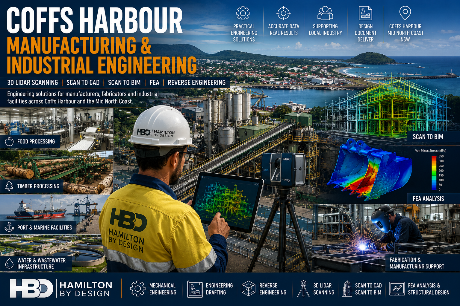


Coffs Harbour Manufacturing & Industrial Engineering

Coffs Harbour manufacturing and industrial engineering services featuring 3D LiDAR scanning, Scan to BIM, FEA analysis, food processing facilities, timber processing plants, marine infrastructure and fabrication workshops.

Coffs Harbour Manufacturing & Industrial Engineering

Engineering Solutions for Manufacturers, Fabricators & Industrial Facilities Across the Coffs Coast

Hamilton By Design provides engineering-led mechanical engineering, 3D LiDAR scanning, Scan to CAD, Scan to BIM, reverse engineering, finite element analysis (FEA) and engineering drafting services throughout Coffs Harbour, Toormina, Sawtell, Woolgoolga, Grafton and the wider North Coast region.

Coffs Harbour is one of regional New South Wales’ most diverse industrial centres, supporting manufacturing, food processing, timber processing, transport infrastructure, marine industries, water utilities and industrial facilities.

As facilities expand and equipment ages, accurate engineering information becomes critical for reducing project risk, improving asset reliability and supporting future growth.

Hamilton By Design helps manufacturers, engineers, fabricators and industrial asset owners capture existing conditions, develop accurate engineering models and deliver practical engineering solutions for both brownfield and greenfield projects.


Engineering Services for Manufacturing & Industry

Supporting Regional Industry Growth

Our services support:

  • Manufacturers
  • Fabricators
  • Timber Processing Facilities
  • Food Processing Plants
  • Water Utilities
  • Industrial Workshops
  • Logistics Facilities
  • Airport Infrastructure
  • Marine Facilities
  • Government Infrastructure

Services include:

  • Mechanical Engineering
  • Engineering Design
  • Reverse Engineering
  • Engineering Drafting
  • FEA Analysis
  • 3D LiDAR Scanning
  • Scan to CAD
  • Scan to BIM
  • Asset Documentation

3D LiDAR Scanning Coffs Harbour

Engineering Grade Reality Capture

Hamilton By Design provides engineering-grade terrestrial laser scanning services throughout Coffs Harbour and Northern NSW.

Laser scanning captures highly accurate site information that can be used for:

  • Existing Condition Surveys
  • Industrial Plant Upgrades
  • Manufacturing Facility Modifications
  • Structural Steel Modelling
  • Pipework Modelling
  • Asset Management
  • Construction Verification

Applications include:

Food Processing Facilities

Capture production equipment, processing lines, conveyors and services prior to upgrades and expansions.

Timber Processing Facilities

Accurately model sawmills, conveyors, log handling systems and timber processing infrastructure.

Industrial Manufacturing Facilities

Document existing plant conditions for engineering design and construction planning.


Sawmill & Timber Processing Engineering

Supporting Brownfield Upgrades

The North Coast has a strong timber processing industry with facilities often containing decades of modifications and undocumented changes.

Hamilton By Design supports:

  • Sawmill Expansions
  • Conveyor Upgrades
  • Dust Extraction Systems
  • Structural Modifications
  • Equipment Replacements
  • Facility Modernisation Projects

Using 3D LiDAR scanning and engineering modelling, we help reduce project risk and improve fabrication accuracy.


Scan to BIM Services

Building Information Modelling for Existing Assets

Hamilton By Design develops BIM models from laser scan data for:

  • Buildings
  • Manufacturing Facilities
  • Industrial Plants
  • Water Infrastructure
  • Utilities
  • Government Assets
  • Airport Infrastructure
  • Processing Facilities

Benefits include:

  • Improved project coordination
  • Reduced design clashes
  • Better asset management
  • Digital Twin Development
  • Enhanced project planning

Finite Element Analysis (FEA)

Engineering Validation Before Fabrication

Hamilton By Design provides FEA services for:

Loader Buckets

  • Wear analysis
  • Structural assessment
  • Reinforcement design

Excavator Buckets

  • Impact load analysis
  • Structural integrity reviews

Grader Blades

  • Ground engagement loading
  • Structural performance verification

Chutes & Hoppers

  • Material loading analysis
  • Wear zone identification
  • Structural optimisation

Industrial Structures

  • Platforms
  • Walkways
  • Support frames
  • Access systems

Reverse Engineering Services

When drawings are unavailable or outdated, reverse engineering allows valuable engineering information to be recovered.

Applications include:

  • Pumps
  • Shafts
  • Castings
  • Conveyor Components
  • Machine Components
  • Structural Assemblies
  • Wear Parts

Deliverables include:

  • SolidWorks Models
  • STEP Files
  • SAT Files
  • Manufacturing Drawings
  • Fabrication Documentation

Why Choose Hamilton By Design?

Engineering-Led Solutions

We understand how engineering information is used throughout the project lifecycle.

Practical Industry Experience

Supporting:

  • Manufacturing
  • Timber Processing
  • Food Processing
  • Utilities
  • Infrastructure
  • Industrial Facilities

Advanced Technology

Using:

  • FARO Focus Laser Scanners
  • FARO Orbis
  • FARO SCENE
  • SolidWorks
  • ANSYS
  • Autodesk Inventor
  • AutoCAD
  • Navisworks

Regional NSW Support

Providing engineering services throughout:

  • Coffs Harbour
  • Sawtell
  • Toormina
  • Woolgoolga
  • Grafton
  • Port Macquarie
  • Kempsey
  • Northern NSW
Hamilton By Design logo displayed on a blue tilted rectangle with a grey gradient background

Talk to Us – Contact Us

Name
Would you like us to arrange a phone consultation for you?
Address

Our clients:
3D LiDAR Scanning Darwin for engineering surveys, laser scanning, reality capture and point cloud modelling services
3D LiDAR Scanning Australia engineering services for laser scanning, reality capture, scan-to-CAD, Scan-to-BIM and as-built documentation across Australia
3D LiDAR scanning services on the Central Coast providing engineering-grade laser scanning, point cloud capture, scan-to-CAD modelling and industrial reality capture for infrastructure and industrial projects.

Port Macquarie Manufacturing & Industrial Engineering

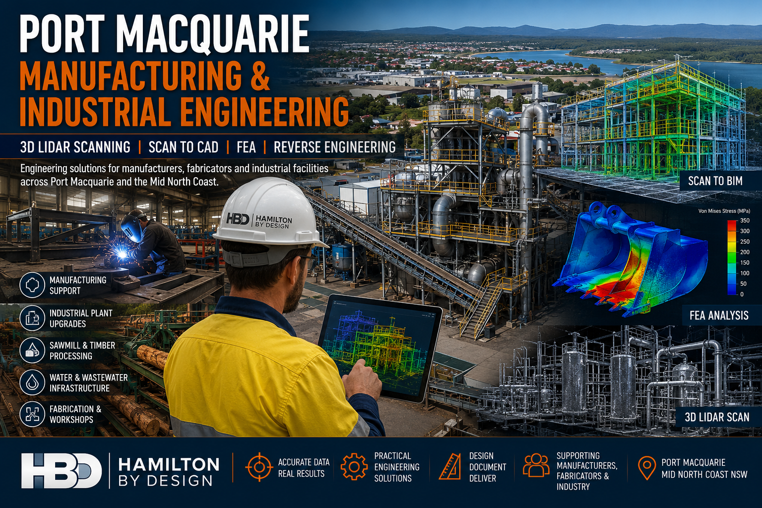
Port Macquarie manufacturing and industrial engineering services featuring 3D LiDAR scanning, Scan to BIM, FEA analysis, fabrication support and industrial plant upgrades by Hamilton By Design.

Port Macquarie Manufacturing & Industrial Engineering

Engineering Solutions for Manufacturers, Fabricators & Industrial Facilities Across the Mid North Coast

Hamilton By Design provides engineering-led mechanical engineering, 3D LiDAR scanning, Scan to CAD, Scan to BIM, reverse engineering, finite element analysis (FEA) and engineering drafting services throughout Port Macquarie, Wauchope, Kempsey, Southwest Rocks, Laurieton and the wider Mid North Coast region.

The Port Macquarie region is home to a growing manufacturing and industrial sector that supports timber processing, food manufacturing, fabrication workshops, transport operators, water infrastructure, marine industries and industrial processing facilities.

As facilities grow and equipment ages, accurate engineering information becomes critical for maintaining productivity, reducing downtime and planning future upgrades.

Hamilton By Design helps manufacturers, engineers, fabricators and asset owners capture existing conditions, develop accurate engineering models and deliver practical solutions for brownfield and greenfield projects.

Whether your project involves upgrading a sawmill, replacing ageing equipment, scanning a processing plant, developing fabrication drawings or validating a design using Finite Element Analysis, our team provides practical engineering support backed by decades of industry experience.


Engineering Services for Manufacturers

Supporting Manufacturing Growth Across Port Macquarie

Manufacturing businesses face increasing pressure to improve productivity, reduce maintenance costs and modernise existing facilities.

Hamilton By Design supports manufacturers by providing:

  • Mechanical Engineering
  • Equipment Design
  • Plant Layout Design
  • Reverse Engineering
  • Engineering Drafting
  • 3D Laser Scanning
  • Scan to CAD
  • Finite Element Analysis
  • Asset Documentation
  • Brownfield Upgrade Support

Our engineering services help manufacturers make informed decisions based on accurate site information and engineering data.


Industrial Plant Engineering

Engineering Support for Existing Facilities

Many industrial facilities have evolved over decades through multiple modifications and expansions.

Unfortunately, original drawings often no longer reflect actual site conditions.

Hamilton By Design provides engineering solutions that allow businesses to accurately document and understand their facilities before commencing upgrades or maintenance projects.

Typical facilities include:

  • Manufacturing Plants
  • Timber Processing Facilities
  • Food Processing Facilities
  • Water Treatment Plants
  • Wastewater Facilities
  • Recycling Facilities
  • Quarry Operations
  • Industrial Workshops
  • Processing Plants

3D LiDAR Scanning Port Macquarie

Engineering Grade Reality Capture

Hamilton By Design provides engineering-grade terrestrial laser scanning services that capture millions of highly accurate measurements.

Laser scanning creates an accurate digital representation of existing facilities and equipment, allowing engineering teams to design with confidence.

Applications include:

  • Manufacturing Facilities
  • Industrial Plants
  • Sawmills
  • Warehouses
  • Water Infrastructure
  • Processing Facilities
  • Structural Steel
  • Pipework Systems
  • Mechanical Equipment

Deliverables include:

  • E57 Files
  • RCP Files
  • RCS Files
  • LAS Files
  • Registered Point Clouds
  • Existing Condition Models
  • Engineering Drawings

Sawmill & Timber Processing Engineering

Supporting Brownfield Upgrades

The Mid North Coast has a long history of timber processing and sawmill operations.

Many facilities have grown over decades and contain a mixture of original equipment, modifications and undocumented changes.

Hamilton By Design supports sawmill operators with:

  • Existing Condition Surveys
  • 3D Laser Scanning
  • Conveyor Design
  • Structural Modifications
  • Dust Extraction Upgrades
  • Equipment Replacement Projects
  • Scan to CAD Services
  • Engineering Documentation

Laser scanning enables accurate modelling of existing plant conditions, reducing project risk and improving installation outcomes.


Scan to CAD Services

Converting Reality into Engineering Information

Point cloud data becomes significantly more valuable when converted into usable engineering deliverables.

Hamilton By Design converts laser scan data into:

  • AutoCAD Drawings
  • Plant Layouts
  • General Arrangement Drawings
  • Equipment Layout Drawings
  • Structural Drawings
  • Mechanical Drawings
  • Fabrication Drawings

These deliverables assist engineers, fabricators and project teams during design and construction activities.


Scan to BIM Services

Building Information Modelling for Existing Assets

Hamilton By Design develops BIM models from laser scan data to support engineering, construction and asset management projects.

We develop BIM models for:

  • Buildings
  • Infrastructure
  • Industrial Facilities
  • Processing Plants
  • Utilities
  • Manufacturing Facilities
  • Water Treatment Facilities
  • Government Assets

Benefits include:

  • Improved project coordination
  • Reduced design clashes
  • Improved construction planning
  • Better asset management
  • Digital Twin Development
  • Enhanced lifecycle management

For industrial facilities and manufacturing operations, Scan to BIM provides an accurate digital foundation for future upgrades and expansion projects.


Mechanical Engineering Services

Practical Engineering Solutions

Hamilton By Design provides mechanical engineering services focused on practical, buildable and maintainable outcomes.

Services include:

  • Mechanical Design
  • Equipment Design
  • Conveyor Design
  • Chute Design
  • Hopper Design
  • Materials Handling Systems
  • Structural Interfaces
  • Equipment Modifications
  • Design Reviews
  • Shutdown Engineering

Our experience spans manufacturing, mining, industrial processing and infrastructure projects throughout Australia.


Finite Element Analysis (FEA)

Engineering Validation Before Fabrication

Finite Element Analysis allows engineers to assess how components and structures perform under load before manufacturing begins.

Hamilton By Design provides FEA services for:

Loader Buckets

Assessment of:

  • Wear zones
  • Reinforcement design
  • Fatigue performance
  • Structural adequacy

Excavator Buckets

Analysis of:

  • Impact loading
  • Structural integrity
  • Wear protection systems
  • Load distribution

Grader Blades

Verification of:

  • Structural support systems
  • Ground engagement loads
  • Deflection performance
  • Wear areas

Chutes & Hoppers

Evaluation of:

  • Material loading
  • Structural performance
  • Impact zones
  • Reinforcement requirements

Industrial Structures

Assessment of:

  • Platforms
  • Walkways
  • Equipment Supports
  • Access Systems
  • Structural Frames

FEA provides confidence that designs will perform safely and efficiently under operational conditions.


Reverse Engineering Services

Recreating Existing Assets

When original engineering drawings are unavailable, reverse engineering can recover valuable engineering information.

Hamilton By Design provides reverse engineering services for:

  • Mechanical Components
  • Pumps
  • Shafts
  • Castings
  • Conveyor Components
  • Wear Liners
  • Structural Components
  • Machinery Assemblies

Deliverables include:

  • SolidWorks Models
  • STEP Files
  • SAT Files
  • Fabrication Drawings
  • Manufacturing Drawings

Engineering Drafting Services

Professional Documentation for Construction & Fabrication

Our drafting services provide accurate engineering documentation for manufacturing, industrial and infrastructure projects.

Services include:

  • Mechanical Drafting
  • Structural Drafting
  • Fabrication Drawings
  • Workshop Drawings
  • As-Built Drawings
  • Construction Documentation
  • Plant Layout Drawings

Using:

  • SolidWorks
  • Autodesk Inventor
  • AutoCAD
  • Navisworks
  • FARO SCENE
  • Autodesk ReCap

Why Choose Hamilton By Design?

Engineering-Led Approach

We understand how engineering information is used throughout the project lifecycle.

Practical Industry Experience

Experience supporting:

  • Manufacturers
  • Fabricators
  • Mining Operations
  • Industrial Facilities
  • Utilities
  • Infrastructure Owners

Advanced Technology

Including:

  • FARO Focus Laser Scanners
  • FARO Orbis Mobile Scanning
  • FARO SCENE
  • SolidWorks
  • ANSYS
  • Autodesk Inventor
  • AutoCAD
  • Navisworks

Australia-Wide Capability

Supporting projects across:

  • Port Macquarie
  • Mid North Coast
  • Newcastle & Hunter
  • Sydney
  • Brisbane
  • Melbourne
  • Adelaide
  • Perth

Hamilton By Design logo displayed on a blue tilted rectangle with a grey gradient background

Need Engineering Support in Port Macquarie?

Whether your project involves manufacturing facilities, industrial plants, sawmills, water infrastructure or brownfield upgrades, Hamilton By Design provides practical engineering solutions backed by real industry experience.

Our Services

โœ” Manufacturing Engineering
โœ” Industrial Engineering
โœ” Mechanical Engineering
โœ” 3D LiDAR Scanning
โœ” Scan to CAD
โœ” Scan to BIM
โœ” Reverse Engineering
โœ” Finite Element Analysis (FEA)
โœ” Engineering Drafting
โœ” Sawmill Engineering Support
โœ” Industrial Plant Upgrades
โœ” Brownfield Engineering Projects

Talk to Us – Contact Us

Name
Would you like us to arrange a phone consultation for you?
Address

Our clients:
3D LiDAR Scanning Darwin for engineering surveys, laser scanning, reality capture and point cloud modelling services
3D LiDAR Scanning Australia engineering services for laser scanning, reality capture, scan-to-CAD, Scan-to-BIM and as-built documentation across Australia
3D LiDAR scanning services on the Central Coast providing engineering-grade laser scanning, point cloud capture, scan-to-CAD modelling and industrial reality capture for infrastructure and industrial projects.

Structural Drafting Perth

Structural Steel Detailing, LiDAR Scanning & Engineering Documentation

Hamilton By Design provides Structural Drafting Perth services for construction, shipbuilding, marine infrastructure, manufacturing, smelting, processing facilities, ports, commercial developments and industrial projects throughout Western Australia.

Our team combines engineering-grade LiDAR scanning, 3D CAD modelling, structural drafting, fabrication detailing and digital project management to create accurate engineering documentation for both Greenfield and Brownfield projects.

Whether you are constructing a new facility, modifying an existing plant, expanding a shipyard or upgrading industrial infrastructure, our workflow is designed to reduce site rework, improve constructability and deliver reliable engineering information.

What Is Structural Drafting?

Structural drafting is the process of converting engineering concepts and calculations into detailed drawings and models used for fabrication, construction and installation.

Structural drafting deliverables may include:

  • General Arrangement Drawings
  • Structural Steel Fabrication Drawings
  • Assembly Drawings
  • Shop Drawings
  • Installation Drawings
  • Weld Details
  • Bolt Schedules
  • Material Take-Offs
  • Bill of Materials (BOM)
  • As-Built Documentation
  • 3D Structural Models

Structural drafting forms the link between engineering design and construction execution.


Industries We Support

Hamilton By Design supports a broad range of industries throughout Perth and Western Australia including:

Construction

  • Commercial buildings
  • Industrial facilities
  • Warehouses
  • Hospitals
  • Education facilities
  • Government infrastructure

Shipbuilding & Marine

  • Shipyards
  • Wharf upgrades
  • Dry dock facilities
  • Marine maintenance facilities
  • Defence infrastructure
  • Port developments

Manufacturing

  • Production facilities
  • Processing plants
  • Packaging facilities
  • Material handling systems

Smelting & Processing

  • Alumina facilities
  • Nickel processing plants
  • Lithium processing facilities
  • Mineral processing plants
  • Industrial processing facilities

Ports & Infrastructure

  • Bulk handling facilities
  • Conveyor systems
  • Transfer stations
  • Storage facilities
  • Materials handling systems

Energy & Utilities

  • Water treatment facilities
  • Wastewater infrastructure
  • Power generation facilities
  • Renewable energy projects

Perth & Western Australia Service Areas

We support projects throughout:

  • Perth
  • Kwinana
  • Henderson
  • Fremantle
  • Welshpool
  • Canning Vale
  • Malaga
  • Bibra Lake
  • Osborne Park
  • Joondalup
  • Bunbury
  • Geraldton
  • Kalgoorlie
  • Port Hedland
  • Karratha
  • Pilbara Region

Greenfield Structural Drafting Workflow

Greenfield projects involve new facilities and new infrastructure.

Step 1 โ€“ Project Planning

Review:

  • Design criteria
  • Client requirements
  • Applicable standards
  • Construction methodology
  • Equipment requirements

Step 2 โ€“ Concept Development

Develop:

  • Facility layouts
  • Structural arrangements
  • Access systems
  • Equipment interfaces
  • Maintenance access requirements

Step 3 โ€“ Engineering Analysis

Engineering verification may include:

  • Wind loading
  • Dead loads
  • Live loads
  • Equipment loads
  • Fatigue assessments
  • Deflection checks

Step 4 โ€“ 3D Structural Modelling

Create digital models for:

  • Buildings
  • Platforms
  • Walkways
  • Pipe racks
  • Shipyard structures
  • Industrial facilities

Step 5 โ€“ Structural Drafting

Produce:

  • General Arrangements
  • Fabrication Drawings
  • Assembly Drawings
  • Installation Drawings
  • Material Schedules

Step 6 โ€“ Construction Support

Provide support during fabrication, installation and commissioning.


Brownfield Structural Drafting Workflow

Brownfield projects involve modifications to existing facilities.

These projects typically require verification of existing conditions before engineering and drafting activities begin.

Step 1 โ€“ Existing Information Review

Review:

  • Existing drawings
  • Vendor information
  • Historical records
  • Asset documentation

Step 2 โ€“ LiDAR Scanning & Site Verification

Capture existing conditions using engineering-grade reality capture technology.

Typical assets captured include:

  • Structural steel
  • Buildings
  • Pipework
  • Equipment
  • Services
  • Access systems

Step 3 โ€“ Point Cloud Registration

Create registered point clouds and digital site environments.

Step 4 โ€“ As-Built Modelling

Develop accurate 3D representations of existing facilities.

Step 5 โ€“ Design Development

Design:

  • Structural modifications
  • New platforms
  • Access systems
  • Equipment supports
  • Pipe bridges
  • Facility upgrades

Step 6 โ€“ Clash Detection

Identify:

  • Structural clashes
  • Mechanical clashes
  • Installation conflicts
  • Access restrictions

Step 7 โ€“ Engineering Validation

Verify:

  • Existing member capacity
  • Connection design
  • Foundation impacts
  • Equipment loading

Step 8 โ€“ Fabrication Detailing

Produce construction-ready documentation for fabrication and installation.

Step 9 โ€“ Construction Support

Support contractors and fabricators during project execution.

Step 10 โ€“ Final Verification

Create final as-built documentation where required.


Software & Technology

Hamilton By Design utilises industry-leading software and hardware throughout the project lifecycle.

Reality Capture

  • FARO Focus S70
  • FARO Orbis
  • FARO SCENE
  • Autodesk ReCap Pro

Design & Drafting

  • SolidWorks
  • AutoCAD
  • Autodesk Inventor
  • Revit

Engineering Analysis

  • SolidWorks Simulation
  • ANSYS
  • SPACE GASS

Construction Review

  • Navisworks

Data Management & Collaboration

  • 3DEXPERIENCE Platform
  • ENOVIA

The 3DEXPERIENCE Platform provides centralised project data management, revision control, document management, engineering workflows and collaboration between engineering, drafting, fabrication and construction teams.


Typical Project Deliverables

Depending on project requirements, deliverables may include:

Drawings

  • PDF Drawings
  • DWG Files
  • DXF Files
  • General Arrangements
  • Fabrication Drawings
  • Installation Drawings

3D Models

  • STEP Files
  • SAT Files
  • Parasolid Files
  • SolidWorks Models
  • Inventor Models
  • IFC Models

Reality Capture Data

  • E57 Files
  • RCP Files
  • RCS Files
  • LAS Files

Engineering Documentation

  • Material Take-Offs
  • Bill of Materials
  • Design Reports
  • As-Built Documentation

Australian Standards Commonly Referenced

Projects may be developed in accordance with applicable standards including:

  • AS 1657 Fixed Platforms, Walkways, Stairways and Ladders
  • AS 4100 Steel Structures
  • AS/NZS 1170 Structural Design Actions
  • AS/NZS 5131 Structural Steelwork Fabrication and Erection
  • AS 3990 Mechanical Equipment Steelwork
  • AS 4991 Lifting Devices
  • AS/NZS 4024 Safety of Machinery

Why Hamilton By Design?

Hamilton By Design combines engineering, drafting and reality capture expertise within a single workflow.

Our team can:

  • Capture existing conditions using LiDAR scanning
  • Create accurate as-built models
  • Develop engineering solutions
  • Perform structural analysis
  • Produce fabrication-ready documentation
  • Manage project information using the 3DEXPERIENCE Platform
  • Support fabrication and construction activities
  • Deliver verified as-built documentation

This integrated approach helps reduce project risk, minimise rework and improve construction outcomes.


Frequently Asked Questions

What is Structural Drafting?

Structural drafting is the preparation of detailed drawings and models used to fabricate and construct structural systems.

What is the difference between Structural Drafting and Structural Engineering?

Structural engineering determines the design requirements, while structural drafting converts the design into construction-ready documentation.

Do you support Brownfield projects?

Yes. Hamilton By Design regularly supports Brownfield upgrades, modifications and expansion projects.

Can LiDAR scanning improve drafting accuracy?

Yes. LiDAR scanning provides accurate existing-condition data that can significantly reduce site rework and clashes.

What software do you use?

We utilise SolidWorks, AutoCAD, Inventor, Revit, ANSYS, SolidWorks Simulation, Navisworks, FARO SCENE, Autodesk ReCap Pro and the 3DEXPERIENCE Platform.

What file formats can be supplied?

DWG, DXF, PDF, STEP, SAT, Parasolid, IFC, E57, RCP, RCS and LAS formats can be supplied depending on project requirements.

Do you provide fabrication drawings?

Yes. We provide fabrication drawings, assembly drawings, installation drawings and material schedules.

Do you support shipbuilding and marine projects?

Yes. We support shipbuilding, marine infrastructure, wharf upgrades and port-related projects throughout Western Australia.

Hamilton By Design logo displayed on a blue tilted rectangle with a grey gradient background

Need Structural Drafting Support?

Whether you’re planning a new facility, upgrading an existing plant, expanding a shipyard, modifying industrial infrastructure or requiring fabrication-ready structural steel drawings, Hamilton By Design can help.

Our team combines engineering-grade LiDAR scanning, 3D modelling, structural drafting and project data management to deliver accurate, constructable solutions.

Our Clients

Speak With an Engineer

Name
Would you like us to arrange a phone consultation for you?
Address

Perth Service Area

Hamilton By Design supports structural drafting, LiDAR scanning, Scan-to-CAD, fabrication drawings and engineering projects throughout Perth and Western Australia.

View our Perth service area location on Google Maps:

From Perth CBD to Henderson, Kwinana, Welshpool, Canning Vale, Bibra Lake, Malaga, Fremantle and regional Western Australia, our team provides engineering-led drafting and reality capture solutions for construction, shipbuilding, manufacturing, smelting, ports and industrial infrastructure projects.

Contact us today to discuss your project requirements.

https://www.hamiltonbydesign.com.au/perth-wa
3D CAD Modelling Australia service banner for Hamilton By Design
Australian Drafting logo featuring bold white text reading "Australian Drafting" centred on a blue rounded rectangle background.
Engineering Governance title graphic featuring bold white text reading "Engineering Governance" centred on a blue rounded rectangle background.
Mechanical, Structural & Pipework Drafting service banner by Hamilton By Design featuring white text on a blue background.
Mechanical engineering services
Blue rounded button with the text โ€œSolidWorks Designโ€ in white.
Finite Element Analysis (FEA) engineering simulation button
3D LiDAR Scanning Darwin for engineering surveys, laser scanning, reality capture and point cloud modelling services
3D LiDAR Scanning Australia engineering services for laser scanning, reality capture, scan-to-CAD, Scan-to-BIM and as-built documentation across Australia
3D LiDAR scanning services on the Central Coast providing engineering-grade laser scanning, point cloud capture, scan-to-CAD modelling and industrial reality capture for infrastructure and industrial projects.
3D LiDAR Scanning Perth for engineering surveys, laser scanning, reality capture and point cloud modelling services
3D LiDAR Scanning Sydney for engineering surveys, laser scanning, reality capture and point cloud modelling services
3D LiDAR Scanning Brisbane for engineering surveys, laser scanning, reality capture and point cloud modelling services
3D LiDAR Scanning Canberra for engineering surveys, laser scanning, reality capture and point cloud modelling services
3D LiDAR Scanning Newcastle for engineering surveys, laser scanning, reality capture and point cloud modelling services
3D LiDAR Scanning Adelaide for engineering surveys, laser scanning, reality capture and point cloud modelling services
https://www.hamiltonbydesign.com.au/scan-to-bim-services-australia-lidar-point-clouds-cad-modelling

SolidWorks Point Cloud to CAD Workflow | From LiDAR Scans to Detailed Engineering Drawings

SolidWorks Workflow for Converting Point Cloud Data into Detailed Engineering Drawings

From Reality Capture to Fabrication Documentation

The rapid adoption of terrestrial LiDAR scanning and engineering-grade reality capture technologies has fundamentally changed the way engineering projects are executed. For decades, engineers, designers and BIM specialists have relied on traditional workflows that begin with conceptual layouts, survey control, architectural envelopes or predefined design models. Today, however, many industrial projects start with something entirely different: a point cloud.

Instead of beginning with assumptions about what exists, engineering teams can now begin with measured reality.

This shift has significant implications for how projects are planned, modelled and documented. It also raises an important discussion regarding the role of Building Information Modelling (BIM), top-down modelling techniques and traditional design workflows when accurate point cloud information is available from the outset.

While BIM remains a powerful methodology, reality capture introduces a different way of thinking that is particularly valuable for brownfield, industrial, mining, manufacturing and infrastructure projects.

The reality is that neither approach is universally better than the other.

As with most engineering decisions, it is often a case of horses for courses.


The Rise of Engineering-Grade Reality Capture

Modern terrestrial LiDAR scanners can capture millions of points every second, producing highly accurate three-dimensional representations of existing facilities.

These systems are now routinely used throughout:

  • Mining operations
  • Mineral processing plants
  • Smelters
  • Power stations
  • Water treatment facilities
  • Manufacturing plants
  • Commercial buildings
  • Hospitals
  • Transport infrastructure
  • Refineries

Unlike traditional survey methods that capture selected points, LiDAR scanning captures entire environments.

The resulting point cloud becomes a digital record of reality.

Engineers can then revisit the site virtually, long after the field work has been completed.

This offers significant advantages including:

  • Reduced site visits
  • Improved safety
  • Faster design development
  • Better clash detection
  • Enhanced stakeholder collaboration
  • Improved asset documentation
  • Accurate retrofit design

For industrial facilities where access may be restricted, hazardous or costly, point cloud data often becomes one of the most valuable project assets available.


Understanding Point Clouds

A point cloud is a collection of millions or billions of measured XYZ coordinates.

Each point represents a location in space.

When combined, these points create a highly detailed representation of physical objects including:

  • Structural steel
  • Pipework
  • Equipment
  • Conveyors
  • Tanks
  • Buildings
  • Mechanical components
  • Electrical services
  • Access systems

Modern scanners may also capture colour information, intensity data and imagery, creating a realistic digital twin of the physical environment.

Unlike traditional CAD models, point clouds contain measured information rather than designed information.

This distinction is important.

A CAD model represents what was intended.

A point cloud represents what actually exists.

For brownfield engineering projects this difference can be substantial.


Why Traditional BIM Workflows Can Struggle

Building Information Modelling originated primarily within the architectural and construction sectors.

The traditional BIM process generally follows a sequence such as:

Concept Design โ†’ Schematic Design โ†’ Detailed Design โ†’ Construction โ†’ Asset Management

The model evolves as the project progresses.

In many BIM workflows the process begins with an architectural envelope or predefined design geometry.

Walls, floors, columns and services are created within a structured modelling environment.

This approach works exceptionally well for:

  • New buildings
  • Greenfield developments
  • Commercial construction
  • Architectural projects
  • Civil infrastructure projects

However, industrial facilities rarely fit neatly into these categories.

A mining plant built over 40 years may contain:

  • Multiple undocumented modifications
  • Legacy equipment
  • Inaccurate drawings
  • Informal field changes
  • Missing records
  • Deformed structures
  • Equipment relocations

In these situations the design model is often less accurate than the physical asset itself.

This creates a challenge.

Traditional BIM workflows frequently assume the model is the primary source of truth.

Reality capture reverses that assumption.

The point cloud becomes the source of truth.

The model simply becomes a representation of measured reality.


Reality-First Engineering

A reality-first workflow begins with data acquisition rather than design assumptions.

The process typically follows:

  1. Site Scanning
  2. Point Cloud Registration
  3. Quality Assurance
  4. Point Cloud Optimisation
  5. Model Development
  6. Engineering Analysis
  7. Drawing Production
  8. Construction Documentation

Instead of asking:

“What should this facility look like?”

The workflow asks:

“What does this facility actually look like?”

This subtle change can significantly improve project outcomes.


SolidWorks and Point Cloud Modelling

SolidWorks has evolved into a powerful platform for working with reality capture data.

While originally developed as a mechanical design system, modern versions provide excellent capabilities for integrating scan data into engineering workflows.

Point clouds can be imported through various formats including:

  • E57
  • LAS
  • XYZ
  • PLY
  • STL
  • OBJ
  • Mesh formats

Depending on project requirements, the workflow may involve:

  • Direct point cloud reference
  • Mesh generation
  • Surface modelling
  • Parametric feature creation
  • Reverse engineering
  • Assembly development

The chosen approach depends on the intended deliverable.


The Importance of Top-Down Modelling

Top-down modelling becomes particularly valuable when working from point cloud data.

Traditional bottom-up modelling involves creating individual components separately before assembling them.

Top-down modelling reverses this process.

The assembly becomes the master model.

Individual components are then developed within the context of the larger system.

For industrial facilities this approach offers significant advantages.


Why Top-Down Modelling Works Well with Point Clouds

A point cloud already contains contextual information.

Pipework exists relative to equipment.

Equipment exists relative to structures.

Structures exist relative to buildings.

Everything already has a defined relationship.

Top-down modelling allows engineers to preserve these relationships.

For example:

A conveyor transfer chute may be modelled directly within the context of:

  • Existing conveyor structure
  • Existing walkways
  • Existing pipework
  • Existing electrical services
  • Existing maintenance access

The design develops within the reality captured environment.

This significantly reduces the risk of clashes.


Skeleton Models and Layout Control

One of the most effective top-down approaches involves the use of skeleton models.

A skeleton model contains:

  • Key reference geometry
  • Design planes
  • Centre lines
  • Control sketches
  • Interface locations

When working from point clouds, the skeleton model can be created directly from measured geometry.

This establishes a reliable framework for the remainder of the design.

Individual components then inherit relationships from the skeleton model.

Benefits include:

  • Improved consistency
  • Faster design changes
  • Better design intent control
  • Reduced assembly errors

Scan-to-CAD Workflow

A typical Scan-to-CAD workflow within SolidWorks may follow the following sequence.

Step 1 โ€“ Site Capture

Engineering-grade LiDAR scanning is completed on site.

Data is collected from multiple scanner positions.

The objective is to capture sufficient coverage while maintaining registration quality.


Step 2 โ€“ Registration

Individual scans are registered into a unified coordinate system.

This produces a complete point cloud.

Quality control is performed to verify registration accuracy.

Typical industrial projects may achieve overall accuracies within several millimetres.


Step 3 โ€“ Point Cloud Cleaning

Noise is removed.

Unwanted objects may be filtered.

Temporary equipment can be excluded.

The objective is to create a usable engineering dataset.


Step 4 โ€“ Import into Modelling Environment

The point cloud is imported into the modelling platform.

At this stage the cloud becomes a digital reference.

The cloud itself is generally not modified.

Instead, engineering geometry is created around it.


Step 5 โ€“ Create Reference Geometry

Reference planes, axes and coordinate systems are established.

These form the foundation of the modelling process.

Top-down methodologies become particularly valuable at this stage.


Step 6 โ€“ Build Parametric Models

Engineering components are modelled using parametric features.

Examples include:

  • Structural steel
  • Tanks
  • Pipework
  • Chutes
  • Platforms
  • Conveyors
  • Ductwork

The resulting model remains editable and fully configurable.


Step 7 โ€“ Validation

The model is compared against the point cloud.

Engineers verify fit, alignment and geometry.

Potential clashes are identified early.


Step 8 โ€“ Drawing Production

Detailed drawings are generated directly from the validated model.

Deliverables may include:

  • General arrangements
  • Fabrication drawings
  • Assembly drawings
  • Pipe spool drawings
  • Structural steel details
  • Installation drawings
  • Bill of materials

Reverse Engineering Using Point Clouds

Reverse engineering is one of the most powerful applications of reality capture.

Many industrial facilities contain components with:

  • Missing drawings
  • Obsolete equipment
  • Unknown suppliers
  • Legacy modifications

Point clouds provide a practical starting point.

Engineers can recreate:

  • Mechanical components
  • Structural systems
  • Pipework networks
  • Fabricated assemblies

The resulting CAD models become valuable engineering assets.


Parametric Models versus Mesh Models

A common mistake is assuming that a mesh model is equivalent to a CAD model.

It is not.

A mesh represents geometry.

A parametric model represents engineering intent.

This distinction is critical.

A parametric SolidWorks model allows:

  • Dimension changes
  • Configuration control
  • Design modifications
  • Manufacturing documentation
  • Finite element analysis

For most engineering applications, converting point clouds into intelligent parametric models provides significantly greater value than simply generating meshes.


Producing Detailed Engineering Drawings

Once a validated model exists, drawing production becomes straightforward.

SolidWorks can automatically generate:

  • Orthographic views
  • Sections
  • Detail views
  • Exploded views
  • Bills of materials
  • Weldment cut lists

This dramatically reduces drafting effort.

Because the drawings originate from the model, consistency is maintained throughout the project.


Brownfield Projects Benefit Most

The reality-first workflow delivers the greatest value in brownfield environments.

These include:

  • Operating mines
  • Smelters
  • Refineries
  • Processing plants
  • Manufacturing facilities
  • Water treatment plants

In these environments accurate existing-condition information is often more valuable than historic drawings.

A point cloud provides a measurable record of the asset as it exists today.


BIM versus Point Cloud Driven Engineering

This discussion is sometimes framed as:

“BIM versus Reality Capture.”

In practice this is the wrong question.

Reality capture and BIM should not be viewed as competing technologies.

They solve different problems.

BIM provides:

  • Information management
  • Design coordination
  • Asset lifecycle management
  • Construction planning
  • Facility management integration

Reality capture provides:

  • Existing-condition verification
  • Accurate geometry
  • Retrofit design support
  • Asset documentation
  • Digital twin creation

The most successful projects often combine both approaches.


A Modern Hybrid Workflow

Increasingly, engineering organisations are adopting a hybrid workflow.

The process becomes:

Reality Capture โ†’ Engineering Model โ†’ BIM Integration

Rather than creating BIM models based on assumptions, the BIM environment is populated using measured reality.

This approach improves confidence throughout the project lifecycle.

The BIM system benefits from more accurate geometry.

The engineering team benefits from reliable site information.

The asset owner benefits from better data quality.

Everybody wins.


The Future of Digital Engineering

The future of engineering is likely to become increasingly reality driven.

Advancements in:

  • LiDAR technology
  • Mobile scanning
  • Drone scanning
  • Artificial Intelligence
  • Automated feature extraction
  • Digital twins

will continue to accelerate the adoption of reality capture workflows.

However, traditional engineering principles remain essential.

Engineers still need to understand:

  • Design intent
  • Structural behaviour
  • Manufacturing processes
  • Construction methods
  • Asset management requirements

Technology provides information.

Engineering provides understanding.


SolidWorks provides an exceptionally capable platform for converting point cloud data into detailed engineering models and fabrication drawings. When combined with top-down modelling methodologies, point clouds become far more than visual references; they become the foundation of the engineering workflow.

Traditional BIM methodologies remain highly effective for greenfield projects and building-centric developments where the design model drives project delivery. However, in brownfield industrial environments the reality often differs from the original design documentation. In these situations, a point cloud frequently becomes the most accurate representation of the asset available.

Rather than viewing BIM and reality capture as competing philosophies, modern engineering teams should recognise the strengths of each approach. BIM excels at information management, coordination and lifecycle planning, while point cloud-driven workflows excel at capturing existing conditions and enabling accurate retrofit design.

Ultimately, the most effective solution is often a hybrid approach that combines the strengths of both. By starting with measured reality, developing intelligent parametric models in SolidWorks and integrating those models into broader BIM environments where appropriate, engineers can reduce risk, improve accuracy and deliver higher quality outcomes.

As digital engineering continues to evolve, the question is no longer whether point clouds should be used. The question is how effectively organisations can transform reality capture data into actionable engineering information that supports design, construction, operation and long-term asset management.

Hamilton By Design logo displayed on a blue tilted rectangle with a grey gradient background

Contact Us – Talk to Us

Name
Would you like us to arrange a phone consultation for you?
Address

Our Clients:

3D CAD Modelling Australia service banner for Hamilton By Design
3D LiDAR scanning and 3D modelling service button โ€” laser scanner capturing a point cloud for engineering and CAD modelling
Mechanical engineering services
3D CAD Modelling Australia service banner for Hamilton By Design
Mechanical, Structural & Pipework Drafting service banner by Hamilton By Design featuring white text on a blue background.
Australian Drafting logo featuring bold white text reading "Australian Drafting" centred on a blue rounded rectangle background.
Blue banner graphic displaying the text "Point Cloud to CAD - Australia" in large white lettering, representing point cloud processing, scan-to-CAD conversion and digital engineering services across Australia.
CHPP Engineering title graphic featuring bold white text reading "CHPP Engineering" centred on a blue rounded rectangle background.
Engineering Governance title graphic featuring bold white text reading "Engineering Governance" centred on a blue rounded rectangle background.
Mechanical engineering services
Australian Drafting logo featuring bold white text reading "Australian Drafting" centred on a blue rounded rectangle background.
3D LiDAR Scanning Hunter & Newcastle banner with white text on a blue background promoting engineering-grade laser scanning services for industrial, mining and infrastructure projects across the Hunter Valley and Newcastle region.
Mechanical Engineering Hunter & Newcastle banner promoting mechanical engineering services for mining, industrial plants, power generation, manufacturing and heavy industry throughout the Hunter Valley and Newcastle region.
Structural Drafting Hunter & Newcastle banner promoting structural drafting services for mining, industrial plants, power generation, manufacturing and infrastructure projects across the Hunter Valley and Newcastle region.
Mechanical Engineering Perth WA banner for Hamilton By Design featuring white text on a blue background.
3D Laser Scanning Perth WA banner for Hamilton By Design with white text on a blue background.
SolidWorks Perth WA banner for Hamilton By Design featuring white text on a blue background.
Fabrication and product design services
Finite Element Analysis (FEA) engineering simulation button
3D LiDAR scanning and 3D modelling service button โ€” laser scanner capturing a point cloud for engineering and CAD modelling
Blue rounded button with the text โ€œSolidWorks Designโ€ in white.
Mechanical drafting services button
Structural drafting services button

Mechanical Engineering | Structural Engineering


3D LiDAR Scanning Darwin for engineering surveys, laser scanning, reality capture and point cloud modelling services
3D LiDAR Scanning Australia engineering services for laser scanning, reality capture, scan-to-CAD, Scan-to-BIM and as-built documentation across Australia
3D LiDAR scanning services on the Central Coast providing engineering-grade laser scanning, point cloud capture, scan-to-CAD modelling and industrial reality capture for infrastructure and industrial projects.