

Industrial 3D Scanning Camellia | Hamilton By Design

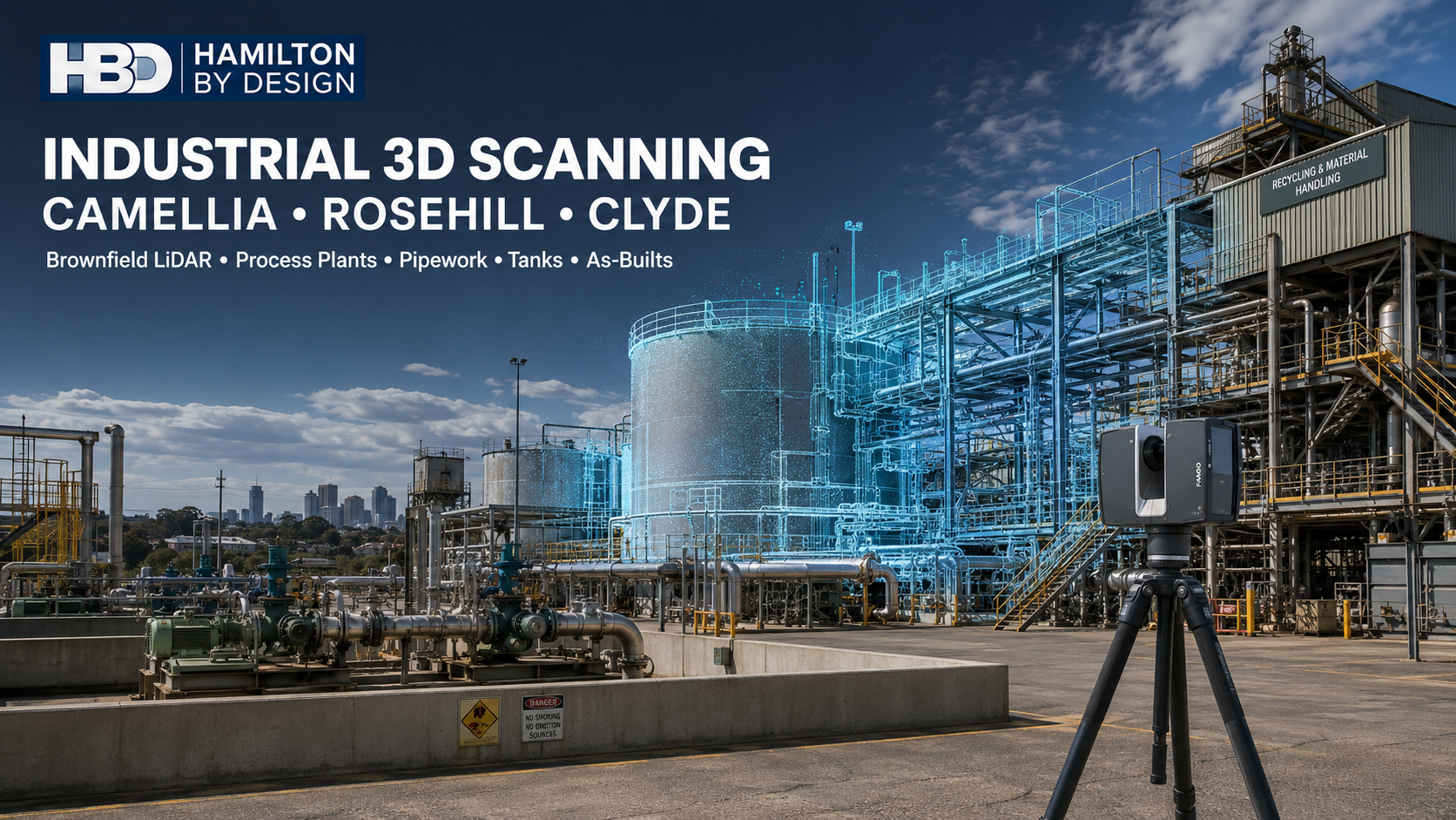
Industrial 3D scanning in Camellia, Rosehill and Clyde, showing a terrestrial LiDAR scanner capturing tanks, process pipework and structural steel.

Industrial 3D Scanning in Camellia, Rosehill and Clyde: Engineering Better Brownfield Decisions

Blue 3D LiDAR scanner icon on a tripod with scanning waves

Camellia, Rosehill and Clyde contain some of the most complex industrial and infrastructure environments in Western Sydney. The area combines bulk-fuel storage, process pipework, recycling facilities, asphalt production, waste handling, transport infrastructure, water assets and former heavy-industrial land.

These facilities frequently contain assets installed or modified over many decades. Original drawings may be incomplete, superseded or inconsistent with what is physically present. Pipework may have been rerouted, structural steel modified, equipment replaced and access systems added without every change being incorporated into the master drawing set.

For asset owners, engineers and contractors, this uncertainty creates a fundamental problem: reliable engineering decisions require reliable information about existing conditions.

Hamilton By Design provides 3D laser scanning for engineering projects across Sydney and Australia. By combining LiDAR capture with mechanical engineering, CAD modelling and technical drafting, we help clients convert complex brownfield sites into accurate and usable engineering information.

An important Western Sydney industrial precinct

Camellia, Rosehill and Clyde remain strategically important because of their proximity to Parramatta, major arterial roads, rail infrastructure, utilities and the broader Sydney industrial market.

The precinct includes several different types of operations:

  • Bulk-fuel receipt, storage and distribution
  • Tank farms, pumping systems and process pipework
  • Asphalt production and reclaimed-asphalt processing
  • Waste transfer and materials recovery
  • Water, wastewater and pipeline infrastructure
  • Transport and light-rail assets
  • Warehousing, maintenance and industrial services
  • Remediation and redevelopment of former industrial land

Viva Energyโ€™s Clyde Terminal operates as a finished-petroleum-product storage and distribution facility. Its infrastructure includes storage tanks, bunds, pumps, pipelines, drainage, instrumentation and firewater systems.

Downerโ€™s Rosehill operations include asphalt production, reclaimed-asphalt processing, material storage and resource-recovery equipment. Veolia also operates waste-management infrastructure in the Clyde area and holds approval for a proposed materials-recycling facility at Camellia.

Sydney Water is progressing plans for substantial water-resource-recovery and pipeline infrastructure within the Camelliaโ€“Rosehill industrial precinct. These established and proposed operations create continuing demand for brownfield investigation, plant documentation, constructability assessment and accurate tie-in information.

Why brownfield industrial sites are difficult to document

A brownfield project is undertaken within or around existing infrastructure. Unlike a new greenfield development, the design team cannot assume that the site is empty, geometrically simple or fully documented.

Industrial brownfield sites commonly contain:

  • Congested pipe racks
  • Closely spaced valves, flanges and cable trays
  • Tanks and pressure equipment
  • Structural frames and access platforms
  • Operating machinery
  • Underground and overhead services
  • Restricted maintenance areas
  • Hazardous substances
  • Traffic and mobile-plant movements
  • Structures that have been modified repeatedly

Traditional site measurement remains useful, but tape measures and isolated measurements cannot efficiently describe every relationship within a complex plant. Small errors in equipment location, flange orientation or structural clearance may result in fabricated components that do not fit.

Engineering-grade LiDAR creates a dense spatial record of visible site conditions. A registered point cloud can show the relationship between pipework, tanks, structures, equipment, platforms and surrounding infrastructure.

Hamilton By Design can then convert selected information into 3D scanning and CAD modelling deliverables suited to the clientโ€™s actual engineering purpose.

Five major problems affecting local industrial facilities

1. Incomplete or unreliable drawings

Many industrial facilities retain drawings from their original construction. However, these documents may not include subsequent maintenance changes, emergency repairs, equipment replacements or production modifications.

Designing from an inaccurate drawing creates avoidable project risk. A pipe shown in the wrong position can affect a new support, platform or equipment installation. An undocumented beam may obstruct a lifting path. A modified stairway may reduce the available maintenance envelope.

LiDAR scanning helps establish a new existing-condition baseline. Historical drawings can be compared with the point cloud, and important differences can be incorporated into updated models and as-built documentation.

2. Congested pipework and difficult tie-ins

Pipework modifications are among the most demanding brownfield activities. New lines must avoid existing services while maintaining appropriate access, support, drainage, isolation and maintenance requirements.

A point cloud can assist engineers in identifying:

  • Existing pipe routes
  • Valve and flange positions
  • Nozzle locations
  • Pipe-rack congestion
  • Structural obstructions
  • Available support locations
  • Access and maintenance clearances
  • Potential tie-in points

Proposed pipework can be modelled within the captured environment before fabrication begins. This reduces reliance on assumptions and supports more informed constructability reviews.

Laser scanning does not determine pipe-wall thickness, material grade, internal condition or process suitability. These matters require appropriate records, engineering assessment and, where necessary, specialist inspection or nondestructive testing.

3. Ageing structures and access systems

Older industrial plants may contain structural steel, platforms, stairs, ladders, handrails and pipe supports that have been exposed to corrosion, vibration, impact or changing loads.

LiDAR can document visible geometry, including member positions, platform levels and apparent displacement. The captured data can support structural assessment, access reviews and the development of replacement or modification concepts.

Where load capacity must be verified, scanning data should be combined with material information, connection details, inspection findings and engineering calculations. Hamilton By Design can also provide finite element analysis and mechanical assessment where FEA is appropriate to the design question.

4. Safety risks around machinery and operational plant

Recycling, asphalt, terminal and process operations may expose personnel to moving machinery, stored energy, hazardous substances, vehicles, elevated work and restricted access.

Hamilton By Design can use captured plant information to support:

  • Machinery risk assessments
  • Guarding reviews
  • Access and egress studies
  • Maintenance-clearance assessments
  • Isolation-point documentation
  • Conveyor and transfer-point reviews
  • Vehicle and pedestrian separation
  • Equipment-removal planning
  • Safer platform and stair concepts

Our industrial machine-guarding design and verification services can help clients identify mechanical hazards and develop practical engineering controls.

Scanning can reduce repeated measurement visits and minimise the amount of time personnel spend close to operating equipment. However, scanning does not replace site induction, permits, isolation procedures, hazardous-area controls or a site-specific safe system of work.

5. Redevelopment and infrastructure interfaces

Camellia, Rosehill and Clyde include continuing industrial operations, remediated land, redevelopment areas and proposed major infrastructure. New work must often be coordinated around retained assets, contaminated ground, operational boundaries and existing utilities.

A coordinated spatial record helps stakeholders understand:

  • What infrastructure currently exists
  • Which assets are retained or removed
  • Where new construction must connect
  • How demolition may affect surrounding plant
  • Whether proposed equipment will physically fit
  • How construction access can be maintained
  • Where interfaces exist between contractors

This information is valuable during concept design, detailed design, procurement, fabrication, installation and final handover.

Brownfield LiDAR and process-plant scanning

Hamilton By Design can capture complete plant areas or targeted zones, depending on the project objective.

Potential applications include:

  • Process-plant scanning
  • Tank and tank-farm documentation
  • Pump and valve station capture
  • Pipe-rack scanning
  • Structural-steel surveys
  • Equipment and machinery capture
  • Plant-room modelling
  • Conveyor and materials-handling layouts
  • Access-platform documentation
  • Shutdown and tie-in planning
  • Demolition studies
  • Installation verification
  • As-built documentation

The purpose of the scan should be established before fieldwork begins. A project intended to produce a general plant layout may require different coverage and modelling detail from a project intended to manufacture a replacement spool or fit a new item of machinery.

This engineering-led approach helps ensure that data is captured for a defined project outcome rather than producing a large point cloud with no clear delivery strategy.

Mechanical engineering and design support

Blue Gear and Spanner icon

A point cloud is a highly useful source of geometric information, but it is not automatically an engineering solution.

Hamilton By Design combines reality capture with mechanical design to help clients progress from existing-condition information to practical project deliverables. Our services can include:

  • Mechanical equipment layouts
  • Pipe-support concepts
  • Machinery and component design
  • Maintenance-access improvements
  • Guarding and safety modifications
  • Equipment replacement studies
  • Lifting and removal assessments
  • Structural interfaces
  • Fabrication-ready CAD models
  • Bills of materials
  • Engineering calculations
  • FEA where appropriate

Because the same team can undertake scanning, modelling and mechanical design, the engineering intent remains connected to the captured site information. This reduces the communication gap that can occur when one contractor scans the facility and an unrelated team later attempts to interpret the point cloud.

Mechanical drafting and manufacturing drawings

Industrial projects eventually require information that fabricators, installers and maintenance personnel can use.

Hamilton By Design provides mechanical drafting services for:

  • General arrangement drawings
  • Fabrication drawings
  • Assembly drawings
  • Weldment drawings
  • Pipe-support drawings
  • Platforms, stairs and guarding
  • Equipment layouts
  • Installation details
  • Sections and elevations
  • Bills of materials
  • As-built drawing updates

Technical documentation may be developed with reference to the AS 1100 series and applicable structural, mechanical, welding, pressure-equipment and client-specific requirements.

Our article explaining how AS 1100 and LiDAR scanning work together outlines how spatial site data can be converted into controlled engineering documentation.

Australian Standards and safety considerations

The applicable standards depend on the asset, process, contractual requirements and intended work. Standards that may be relevant to industrial projects in Camellia, Rosehill and Clyde include:

  • AS 1100 series for technical drawing
  • AS 1210 for pressure vessels
  • AS 4041 for pressure piping
  • AS/NZS 1200 for pressure equipment
  • AS 1657 for fixed platforms, walkways, stairs and ladders
  • AS 1940 for flammable and combustible liquids
  • AS 4100 for steel structures
  • AS/NZS 1170 series for structural design actions
  • AS/NZS 4024 series for machinery safety
  • AS/NZS IEC 60079 series for explosive atmospheres
  • AS 2865 for confined spaces
  • AS ISO 31000 for risk management
  • AS 1418 and AS 2550 series for cranes, hoists and their safe use
  • AS 2359 series for powered industrial trucks
  • AS 4991 for lifting devices

Hamilton By Design has prepared an overview of Australian Standards relevant to engineering, scanning and documentation projects.

The applicable standard, edition and acceptance criteria must be confirmed for each project. Scanning assists the engineering process by improving existing-condition information; it does not, by itself, certify that a plant or structure complies with a particular standard.

Engineering support for industrial logistics

Industrial logistics involves more than truck access. Equipment, materials, maintenance personnel and waste streams must move safely through constrained operational environments.

Hamilton By Design can assist with:

  • Loading and unloading layouts
  • Forklift and pedestrian separation
  • Vehicle and mobile-plant interfaces
  • Equipment-removal routes
  • Crane and lifting access
  • Laydown-area planning
  • Maintenance staging
  • Shutdown sequencing
  • Conveyor and transfer arrangements
  • Clearance assessment beneath structures
  • Transport and installation frames

A three-dimensional model allows movement paths and physical clearances to be reviewed before site mobilisation. This is particularly useful where a large component must pass through an existing plant, underneath pipework or between operating assets.

Retaining a reliable plant-data baseline

A scan should not be treated as a short-term project by-product. When appropriately managed, it can become a valuable plant information resource.

Hamilton By Design can retain or help clients manage:

  • Registered process-plant point clouds
  • Pipe-route information
  • Tank and nozzle geometry
  • Structural-steel models
  • Equipment layouts
  • Tie-in information
  • As-built drawings
  • Modification records
  • Plant baseline datasets

Retention arrangements should address ownership, confidentiality, cybersecurity, revision control, permitted users, file formats and the agreed retention period.

Future projects can refer to the baseline dataset, although critical dimensions should be checked where the site may have changed since the original scan.

Who benefits from industrial 3D scanning?

Industrial 3D scanning can assist:

  • Asset owners
  • Plant managers
  • Maintenance teams
  • Project engineers
  • Reliability engineers
  • Mechanical and structural engineers
  • Equipment suppliers
  • Fabricators
  • Construction contractors
  • Demolition contractors
  • Safety professionals
  • Industrial developers

The greatest value is generally achieved when scanning is integrated into the engineering workflow from the beginning of the project.

Frequently asked questions

What is industrial 3D laser scanning?

Industrial 3D laser scanning uses LiDAR technology to measure visible surfaces and create a three-dimensional point cloud. The point cloud records the spatial relationship between equipment, structures, pipework and surrounding plant.

Can scanning replace existing engineering drawings?

Scanning can be used to verify, update or supplement existing drawings. The point cloud itself is not automatically a controlled engineering drawing. Selected information must be interpreted, modelled and documented in an appropriate CAD or BIM format.

Can Hamilton By Design scan an operating process plant?

Yes, subject to the clientโ€™s access requirements, permits, inductions, hazardous-area controls and safe work procedures. A site-specific capture plan should identify operating restrictions and areas that cannot be safely accessed.

Can LiDAR see through tanks, pipes or walls?

No. LiDAR records surfaces that are visible from the scanner position. It does not see through solid objects or determine internal pipe condition, wall thickness or material composition. Multiple scan positions are used to reduce line-of-sight shadows.

What deliverables can be produced?

Deliverables may include registered point clouds, viewer files, 2D layouts, 3D CAD models, BIM models, equipment arrangements, pipework models, structural models, fabrication drawings and as-built documentation. The appropriate deliverable depends on the intended engineering use.

Is 3D scanning the same as surveying?

Not necessarily. Hamilton By Design provides engineering-focused reality capture and modelling. Where cadastral boundaries, registered survey certification or formally controlled survey coordinates are required, a suitably qualified surveyor should establish or verify the necessary control.

Can point clouds support pipework modifications?

Yes. Point clouds can document existing pipe routes, supports, flanges, valves, structures and surrounding obstructions. Proposed pipework can then be modelled against the captured environment to improve tie-in planning and reduce clashes.

Can scanning identify corrosion or structural defects?

Scanning can document visible geometry and, in some cases, apparent deformation. It does not replace detailed inspection, material testing, thickness measurement or specialist NDT. These inputs can be combined with the captured geometry for a broader engineering assessment.

How accurate is industrial laser scanning?

Accuracy depends on the scanner, range, surface properties, environmental conditions, scan geometry, registration method and survey control. The required tolerance should be agreed before scanning so the capture and verification process can be planned appropriately.

Why use an engineering company for LiDAR scanning?

An engineering-led scanning team can plan the capture around the intended design, fabrication or safety outcome. Hamilton By Design can interpret the point cloud, develop engineering models and progress the information into drawings and practical design solutions.

Better information for safer industrial decisions

Brownfield projects are difficult because existing conditions are complex, congested and not always properly documented. Industrial 3D scanning gives project teams a more reliable basis for design, coordination and planning.

For facilities in Camellia, Rosehill and Clyde, the combination of heavy industry, process plant, tanks, pipework, recycling equipment and major infrastructure makes accurate site information especially valuable.

Hamilton By Design combines engineering-grade LiDAR scanning with mechanical engineering, 3D modelling, drafting and safety-focused design. Our objective is not simply to scan a site. It is to turn captured information into practical engineering deliverables that help clients reduce uncertainty, improve constructability and make better-informed brownfield decisions.


Hamilton By Design logo displayed on a blue tilted rectangle with a grey gradient background

Contact Us – Talk To Us

Name
Would you like us to arrange a phone consultation for you?
Address

Our clients:


3D Laser Scanning Smeaton Grange | Factory Engineering

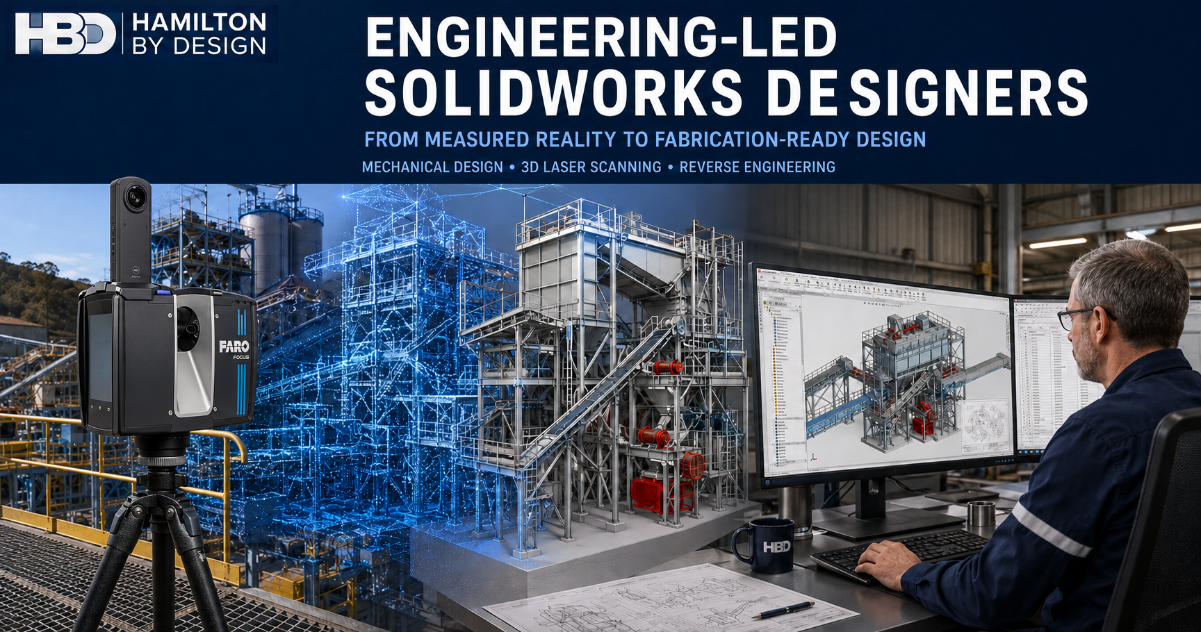
Engineer using a 3D laser scanner in a Smeaton Grange factory with point-cloud and CAD conveyor overlays.

3D Laser Scanning and Mechanical Engineering in Smeaton Grange NSW

Blue 3D LiDAR scanner icon on a tripod with scanning waves

Smeaton Grange is one of the Macarthur regionโ€™s most important industrial precincts. Its factories, workshops and warehouses support food production, machinery manufacture, surface engineering, mining equipment, truck and trailer manufacturing, printing, pharmaceutical production, materials handling and logistics.

For businesses operating in this environment, the engineering challenge is rarely starting with a completely empty building. Most projects involve existing machinery, undocumented modifications, congested services and production schedules that allow very little time for installation errors. Hamilton By Design helps clients manage these risks by combining engineering-grade LiDAR scanning with mechanical engineering, reverse engineering and fabrication-ready documentation.

Supporting Smeaton Grangeโ€™s Industrial Operations

Publicly documented facilities in the precinct include fresh-food processing, trailer and conveyor manufacturing, surface engineering, signage production, complementary-medicine manufacturing and mining ground-support production. This does not imply that these businesses are HBD clients, but it demonstrates the areaโ€™s engineering diversity.

Across these industries, new machinery must be fitted around existing columns, conveyors, platforms, pipework, electrical services and access routes. Older machines may no longer have reliable drawings, while production lines may have been modified several times without the factory layout being updated.

Hamilton By Design can capture these existing conditions and convert them into practical engineering information for factory upgrades, equipment replacement and long-term asset management.

Five Common Factory Engineering Problems

1. Missing or Outdated Drawings

Many factories have drawings that no longer reflect the installed plant. Equipment, services, platforms and guards may all have changed. Designing from unreliable information increases the risk of clashes, rework and delays.

A 3D laser scan creates a measurable point-cloud record of the current factory. This can be used to develop verified layouts, sections, elevations and equipment-interface models.

2. New Equipment Must Fit a Congested Factory

Installing a conveyor, packaging machine or production cell inside an operating factory is difficult. Small dimensional errors can affect product flow, services, maintenance access and guarding.

HBDโ€™s manufacturing layout design workflow allows proposed equipment to be coordinated with actual installed conditions before fabrication or installation begins.

3. Obsolete Machinery Parts Cannot Be Purchased

Factories often operate reliable machines long after supplier support ends. When a component fails, there may be no CAD model, drawing or replacement available.

Hamilton By Design provides reverse-engineering 3D scanning to capture existing components and develop replacement models. The objective is not simply to copy a worn part, but to understand its function, interfaces, tolerances and potential failure mechanisms before preparing a replacement.

4. Machinery Guarding Is Incomplete or Unsuitable

Factory modifications can expose shafts, couplings, chains, belts, pulleys, rollers and nip points. Guards may also be damaged, removed or altered to clear replacement equipment.

HBD provides machine-guarding design and engineering for existing and modified machinery. Scanning can capture the hazard area, available mounting points, maintenance access and surrounding obstructions so that guards fit the installed equipment.

5. Shutdown Time and Installation Rework Are Expensive

Factories cannot stop production for repeated measurements. Poor fit-up can create extra crane time, site cutting, welding, delayed commissioning and lost production.

Capturing the factory once and completing coordination digitally can reduce these risks and support a more controlled shutdown plan.

Engineering Tools for Factory Problems

Different tools suit different scales of work. A FARO Focus terrestrial scanner can capture buildings, structural steel and machinery lines. Mobile LiDAR supports rapid walkthrough capture, while handheld scanning can record smaller components and complex surfaces.

FARO SCENE and Autodesk ReCap can be used to register, review and export point-cloud information. The verified data can then be developed through SolidWorks 3D modelling and AutoCAD. Navisworks can support coordination and clash reviews where several models or disciplines are involved.

SolidWorks Simulation and FEA may be used where brackets, frames or components require assessment. For chutes, hoppers and bulk-product transfers, HBD can also apply its material-handling engineering experience and discrete element modelling where appropriate.

Mechanical Engineering Services

Hamilton By Designโ€™s mechanical engineering consulting can support factory and warehouse projects involving:

  • Production-line and conveyor modifications
  • Machinery and equipment replacement
  • Reverse engineering
  • Platforms, stairs and maintenance access
  • Guarding and safety barriers
  • Equipment-support frames
  • Factory relocation and machinery consolidation
  • Brownfield installation planning
  • Mechanical assessment and FEA

Depending on the scope, designs may consider AS/NZS 4024 for machinery safety, AS 3990 for mechanical-equipment steelwork, AS 4100 for steel structures, AS/NZS 1170 for structural actions, AS/NZS 1554.1 for structural welding and AS 1657 for fixed platforms, walkways, stairs and ladders.

Mechanical Drafting and Fabrication Documentation

Scanning and engineering analysis only create value when the information can be used by manufacturers, fabricators and installers. HBDโ€™s mechanical drafting services can produce:

  • Factory and production-line layouts
  • General arrangement drawings
  • Fabrication and assembly drawings
  • Guarding and sheet-metal details
  • Conveyor layouts and support details
  • Installation drawings
  • DXF profiles
  • Bills of materials
  • SolidWorks, STEP, Parasolid, DWG and PDF deliverables

Drawing presentation can follow the relevant parts of AS 1100, including general technical-drawing and mechanical-engineering drawing conventions. Project drawings should also identify the applicable materials, welding, tolerances, finishes and site requirements.

Machinery Safety and Conveyor Engineering

Effective guarding must consider foreseeable access, cleaning, inspection, lubrication, adjustment and maintenanceโ€”not simply place a barrier around moving machinery.

HBD can assist with guarding inspections, gap assessments, fixed guards, removable panels, perimeter guarding, maintenance openings, access gates and fabrication documentation. Electrical interlocks, emergency-stop circuits and functional-safety validation should be coordinated with an appropriately qualified electrical or control-systems specialist.

In NSW, machinery projects operate within the Work Health and Safety Act 2011 and Work Health and Safety Regulation 2025. Relevant technical guidance may include AS/NZS 4024.1201 for machinery risk assessment, AS/NZS 4024.1601 for guards, AS/NZS 4024.1803 for minimum gaps and AS/NZS 4024.1604 for emergency-stop principles.

Conveyor projects should use the relevant current AS/NZS 4024 conveyor standards. These include AS/NZS 4024.3610 for general conveyor requirements, AS/NZS 4024.3611 for bulk-material belt conveyors and AS/NZS 4024.3612 for chain and unit-handling conveyors. The older AS 1755 conveyor standard has been superseded and should not be treated as the primary standard for a new design.

Engineering for Warehousing and Logistics

Smeaton Grange is also a significant freight and logistics precinct. Warehouses may include conveyors, sortation equipment, palletisers, storage racking, loading areas, forklifts and pedestrian routes.

Hamilton By Design can scan warehouse interiors and document building columns, racking, conveyors, platforms, equipment and loading interfaces. Proposed changes can then be reviewed for equipment clearance, maintenance access, guarding and installation sequencing.

Depending on the project, relevant standards may include AS/NZS 4024.3612 for unit-handling conveyors, AS 4024.3404 for palletisers and depalletisers, AS 4084 for steel storage racking and AS 2359 for powered industrial trucks. Proprietary racking should remain subject to design and verification by the competent racking supplier or engineer.

Retaining a Reusable Digital Factory Record

The point cloud and CAD information created for one project can continue supporting future work. Subject to agreed confidentiality and retention arrangements, HBD can retain factory point clouds, machine models, conveyor layouts, equipment interfaces, CAD assemblies and fabrication drawings.

This gives the client a verified engineering baseline for later modifications and reduces the need to start each project with incomplete drawings and repeated site measurement.

Frequently Asked Questions

Can Hamilton By Design scan an operating factory?

Yes. Scanning can often proceed around normal operations, subject to site safety and access. Some areas may require a shutdown where moving equipment or product flow prevents safe capture.

Can scan data be converted into SolidWorks or AutoCAD?

Yes. Point clouds can support SolidWorks models, AutoCAD layouts, general arrangements, fabrication drawings and equipment-interface models. The required modelling level should be agreed first.

Can HBD reverse engineer an obsolete machine part?

Yes. HBD can capture the component, assess its interfaces and develop manufacturing information. Worn geometry should not be copied without considering function, tolerances, material and loads.

Can machine guards be designed from a point cloud?

Yes. Scanning is especially useful for retrofit guarding because it records the machinery, existing supports and nearby obstructions. HBD can prepare guard models, mounting details, fabrication drawings and bills of materials.

Does HBD design conveyors for factories and warehouses?

HBD can assist with conveyor layouts, modifications, supports, transfers, equipment interfaces and guarding. The exact engineering scope depends on conveyor type, product, capacity, controls and operating environment.

Does HBD retain the scan and CAD data?

Data can be retained subject to agreed client permissions, confidentiality and storage arrangements. Retention allows later projects to reuse the verified factory information rather than beginning again with incomplete records.

Discuss a Smeaton Grange Project

Hamilton By Design provides industrial 3D scanning and engineering support across Sydney, including Smeaton Grange and the wider Macarthur industrial region.

Whether the requirement involves factory scanning, reverse engineering, machinery guarding, conveyor modifications or fabrication-ready drawings, HBD can help convert existing conditions into practical engineering outcomes.


Hamilton By Design logo displayed on a blue tilted rectangle with a grey gradient background

Contact Us – Talk To Us

Name
Would you like us to arrange a phone consultation for you?
Address

Our clients:


3D Laser Scanning Prestons | Factory Engineering

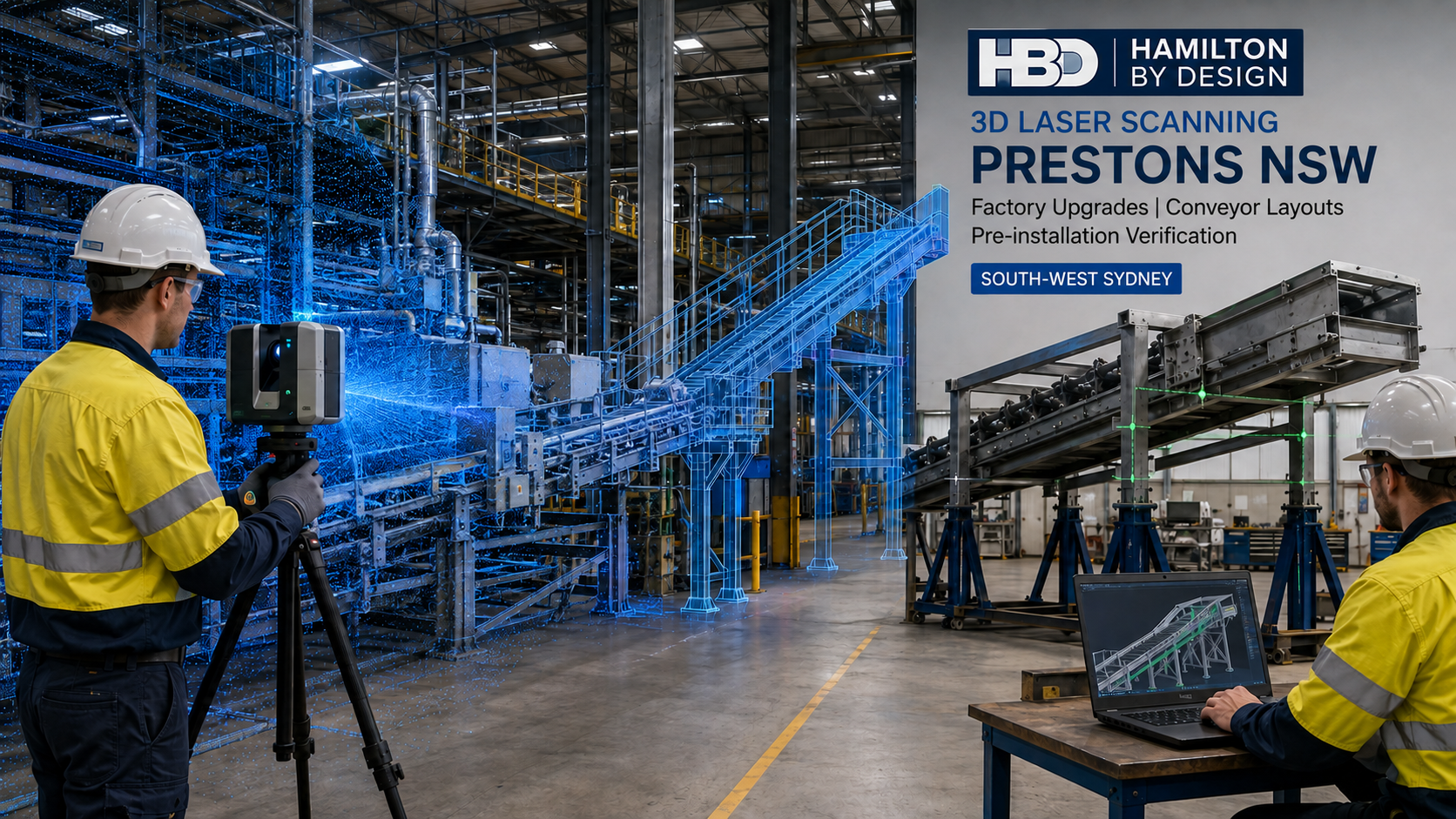
3D laser scanning in a Prestons NSW factory showing point-cloud capture, conveyor modelling and installation verification.

3D Laser Scanning Prestons for Factory Upgrades and Installation Verification

Factories and warehouses must change as production and operational requirements develop. Companies may need to install new machinery, modify conveyors or increase production capacity. However, these projects become difficult when the existing drawings no longer match the facility.

Hamilton By Design provides engineering-led 3D laser scanning in Prestons for factories, warehouses and industrial facilities. We capture existing conditions before design, fabrication or installation begins.

The resulting point cloud provides a reliable foundation for plant modelling, conveyor layouts, mechanical design and clash detection. It can also help verify machinery and fabricated structures before a planned production shutdown.

Supporting Industrial Businesses in Prestons NSW

Prestons NSW 2170 is an established industrial precinct within the Liverpool local government area. Its proximity to the M5, M7 and Hume Highway makes it suitable for manufacturing, warehousing, freight and distribution operations.

Businesses in Prestons manufacture, assemble, store or distribute many different products. These include:

  • Mining ventilation and water-management equipment
  • Electrical switchboards and building products
  • Fabricated steelwork and mechanical components
  • Synthetic turf and other manufactured materials
  • Food, beverages and packaged products
  • Chilled and frozen goods
  • Retail and consumer products
  • Industrial equipment and replacement parts

Prestons is not a mineral-producing location. However, several local businesses manufacture or distribute equipment for mining, infrastructure and industrial projects.

Other companies operate warehouses, fulfilment centres and cold-storage facilities. These operations often use conveyors, racking, platforms and automated handling systems. Therefore, accurate facility information becomes important when equipment or layouts change.

The Problem with Outdated Factory Drawings

Existing factory modifications can be difficult to engineer when drawings are incomplete or outdated. The drawings may also show the original building without later machinery and service changes.

This situation does not apply to every Prestons facility. Some newer buildings have reliable construction drawings or BIM models. However, even a modern warehouse can change after construction.

For example, a business may relocate machinery, install racking or extend a conveyor. Contractors may also add pipework, cable trays, platforms or ducting. Unfortunately, those changes may not appear in the original drawings.

As a result, the design team may work with incorrect dimensions or incomplete information. This creates several potential problems:

  • Incorrect machinery and equipment interfaces
  • Misaligned conveyor elevations or centre lines
  • Clashes with structural steel or building services
  • Insufficient access for operators and maintenance teams
  • Incorrect baseplate, foundation or bolt-hole positions
  • Fabricated components that do not fit
  • Additional site measurements and redesign
  • Longer installation and production shutdowns

Hamilton By Designโ€™s industrial 3D scanning services provide a measurable record of the facility. Therefore, the project team can design from current site conditions instead of relying only on older drawings.

Establishing an Accurate Existing-Condition Baseline

A 3D laser scanner captures millions of measured points across a factory or warehouse. Together, these points form a three-dimensional point cloud.

The point cloud records the visible surfaces of:

  • Machinery and production equipment
  • Conveyors and transfer points
  • Structural steel and supports
  • Floors, walls and building columns
  • Platforms, stairs and walkways
  • Pipework and ducting
  • Cable trays and building services
  • Equipment bases and foundations
  • Doorways and installation routes

Hamilton By Design can use terrestrial or mobile 3D laser scanning to capture the required area. The scan may cover one machine, a production line or an entire warehouse.

Next, we register and review the scan data. This creates a coordinated point cloud that engineers can measure and use for design.

Hamilton By Design can then develop point-cloud models for Sydney industrial projects. Importantly, the modelling scope can focus on the equipment and interfaces that affect the project. This avoids unnecessary modelling while retaining the required engineering detail.

Verifying Equipment Before a Production Shutdown

Production shutdowns often provide a limited installation window. During this period, contractors must remove existing equipment and install the replacement system. The business then needs to return the plant to operation.

A dimensional problem discovered during the shutdown can cause serious delays. It may require site cutting, welding, drilling or replacement fabrication. In addition, the business may face extra labour, crane hire and lost production costs.

Hamilton By Design can help identify these problems before the shutdown begins.

First, we scan the proposed installation area. We then place the new machinery or structural model within the existing-condition point cloud. This process allows us to check:

  • The available installation envelope
  • Machinery and structural interfaces
  • Baseplate and foundation locations
  • Conveyor connection points
  • Upstream and downstream alignment
  • Maintenance and operator access
  • Crane and lifting clearances
  • Potential clashes with existing services
  • Structural connection positions
  • Access for transporting equipment into the building

Hamilton By Design can also scan a completed component or structure at the fabricatorโ€™s workshop. We can then compare its geometry with the approved CAD model and the available site space.

This verification process may identify dimensional differences before the fabricator sends the item to site. Consequently, the workshop can make corrections under controlled conditions. This is usually easier than modifying the equipment during a production shutdown.

Scanning does not remove every installation risk. Site movement, fabrication tolerances and contractor methods can still affect the outcome. Nevertheless, pre-installation verification provides much greater fit-up confidence.

From Factory Scanning to Mechanical Engineering

The point cloud is the starting point rather than the final engineering outcome.

Hamilton By Design combines reality capture with mechanical engineering services in Sydney. This allows us to support a project from site capture through to design and documentation.

Our services can include:

  • Factory and production-line scanning
  • Existing-condition and as-built verification
  • Conveyor and materials-handling layouts
  • Machinery modification and integration
  • Plant and facility modelling
  • Structural and equipment supports
  • Platform, stair and access design
  • Machine guarding layouts
  • Clash and clearance detection
  • General arrangement drawings
  • Fabrication and installation drawings
  • Parts lists and DXF cutting profiles
  • Post-installation verification

Hamilton By Design can convert scan data into engineering-grade 3D CAD models. Depending on the project, deliverables may include SolidWorks, Inventor, STEP, Parasolid, DWG or DXF files.

We can also provide registered point clouds in formats such as E57, RCP, RCS or LAS.

Manufacturing and Production Engineering

Manufacturers may need to introduce new products or improve their current processes. They may also need to remove bottlenecks, increase throughput or improve maintenance access.

Hamilton By Designโ€™s manufacturing and production engineering services can support:

  • Machinery upgrades
  • Special-purpose equipment
  • Production-line modifications
  • Conveyor and transfer layouts
  • Equipment frames and supports
  • Maintenance-access improvements
  • Machine guarding
  • Fabrication documentation
  • Installation planning
  • Final as-built verification

In some cases, replacement parts are no longer available. Alternatively, the original drawings may not accurately represent the installed component.

Hamilton By Design can use reverse-engineering 3D scanning to capture the componentโ€™s physical geometry. Engineers can then assess the design, materials and operating requirements before preparing a replacement.

Conveyor and Materials-Handling Engineering

Manufacturers, warehouses and distribution centres often rely on conveyors to maintain production and product flow.

However, conveyor modifications require more than a simple route between two points. The designer must consider elevations, transfer positions, surrounding structures and maintenance access. Guarding, platforms and building services can also affect the available space.

Laser scanning can establish:

  • Conveyor centre lines
  • Head and tail pulley locations
  • Transfer elevations
  • Existing support positions
  • Chute and hopper interfaces
  • Walkway and maintenance clearances
  • Nearby machinery and services

The proposed conveyor can then be modelled within the point cloud. As a result, the design team can identify clashes before fabrication begins.

For bulk-material applications, HBDโ€™s materials-handling engineering services can also assist with chutes, hoppers, transfer stations, wear protection and material-flow improvements.

Reducing Physical, Engineering and Financial Risk

Accurate existing-condition information helps reduce three main categories of risk.

Physical and safety risk

Poorly coordinated equipment can restrict access or interfere with operating machinery. It may also affect guarding, lifting arrangements and maintenance activities.

Engineering risk

Incorrect dimensions can cause misaligned conveyors, unsuitable connections and inadequate clearances. In addition, an incomplete design basis can affect structural or mechanical assessments.

Financial and programme risk

Fabrication rework, extra site labour and delayed crane activities can increase project costs. More importantly, installation problems can extend the shutdown and delay the return to production.

Therefore, scanning and pre-installation verification should form part of the projectโ€™s risk-management process.

Retaining a Digital Facility Record

Subject to agreed data-security and retention arrangements, Hamilton By Design can maintain a digital project baseline.

This information may include:

  • Registered point clouds
  • Facility and plant models
  • Equipment locations
  • Conveyor routes and elevations
  • Supplier CAD models
  • Construction comparison models
  • Post-installation scans
  • Engineering drawings and revision records

The retained information can support future modifications and maintenance planning. However, each dataset should record its capture date. The project team should also confirm whether later site changes have occurred.

Relevant Australian Standards

The applicable standards depend on the equipment, loads and engineering scope. Potentially relevant standards include:

  • AS/NZS 4024 series โ€“ safety of machinery
  • AS/NZS 4024.3610 โ€“ conveyor-system safety
  • AS 1657 โ€“ fixed platforms, walkways, stairways and ladders
  • AS 3990 โ€“ mechanical-equipment steelwork
  • AS 4100 โ€“ steel structures
  • AS/NZS 1170 series โ€“ structural design actions
  • AS 4084.1 โ€“ steel storage racking
  • AS 4991 โ€“ lifting devices

Laser scanning records the existing geometry. However, it does not demonstrate engineering compliance on its own. Engineers must assess the design against the standards that apply to the project.

Frequently Asked Questions

What is 3D laser scanning used for in a Prestons factory?

3D laser scanning captures existing machinery, conveyors, steelwork and building services. Engineers can then use the point cloud for modifications, equipment integration, modelling and as-built documentation.

Can scanning confirm whether new equipment will fit?

Yes. Hamilton By Design can place the proposed equipment model within the site point cloud. We can then review its interfaces, clearances and potential clashes before installation.

Can HBD verify fabricated steelwork before delivery?

Yes, depending on the scope and required tolerances. HBD can scan the completed structure and compare it with the approved CAD model. We can also check it against the existing site envelope.

Can Hamilton By Design scan an entire warehouse?

Yes. We can capture a defined machinery area, a production line or a larger industrial facility. The scanning and modelling scope will depend on the required engineering outcome.

What files can Hamilton By Design provide?

Available formats may include E57, RCP, RCS, LAS, DWG, DXF, STEP and Parasolid. HBD can also provide SolidWorks or Inventor models, general arrangements and fabrication drawings.

Does 3D laser scanning replace mechanical engineering?

No. Scanning captures the visible geometry. Engineers must still assess loads, materials, tolerances, structural capacity, safety and compliance.

How does scanning reduce shutdown risk?

Scanning allows the project team to check equipment and interfaces before production stops. Therefore, designers and fabricators can resolve many dimensional problems before the shutdown begins.

Can HBD retain the scan data for future modifications?

Yes, subject to agreed ownership, confidentiality and retention arrangements. The scans and facility models can provide a useful baseline for later projects.

Discuss a Prestons Factory or Warehouse Project

Hamilton By Design provides engineering-led 3D laser scanning, plant modelling and mechanical design throughout Prestons and South-West Sydney.

We can assist with factory upgrades, conveyor layouts, machinery installation and clash detection. We can also verify components and structures before a planned production shutdown.

By combining accurate site capture with practical engineering experience, Hamilton By Design helps project teams reduce uncertainty and improve installation confidence.


Hamilton By Design logo displayed on a blue tilted rectangle with a grey gradient background

Contact Us – Talk To Us

Name
Would you like us to arrange a phone consultation for you?
Address

Our clients:


3D Laser Scanning Wetherill Park | Reverse Engineering & Mechanical Design

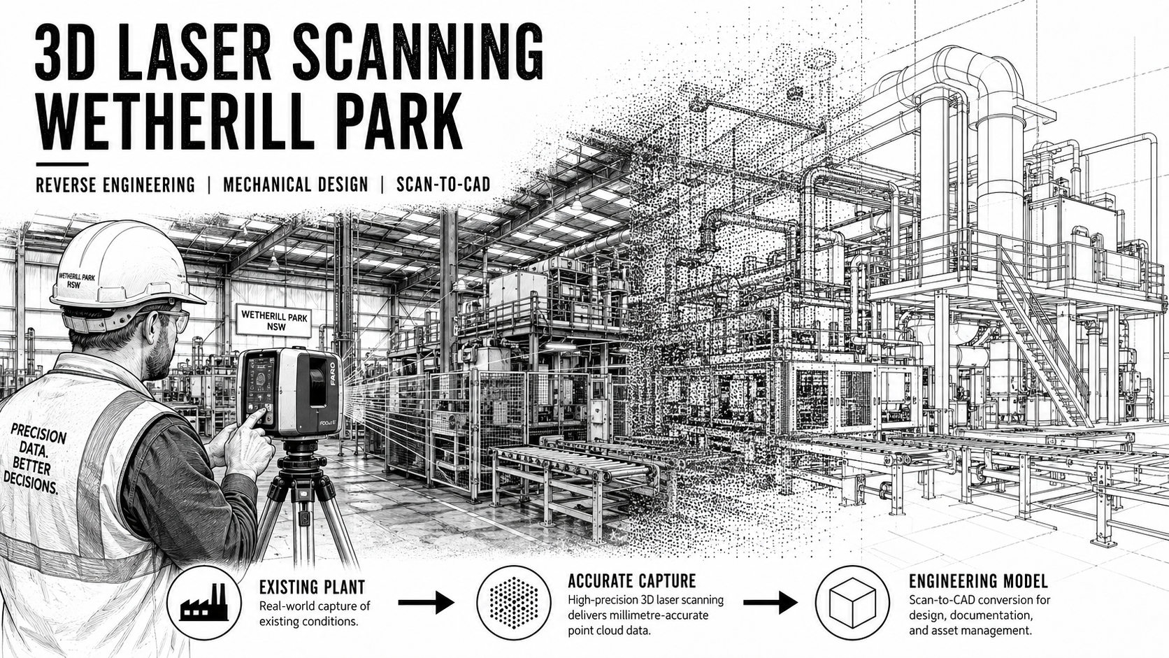
Black-and-white illustration of 3D laser scanning in a Wetherill Park factory, showing an engineer scanning industrial machinery as the plant transitions from existing conditions to point-cloud data and a CAD engineering model.

3D Laser Scanning Wetherill Park | Reverse Engineering & Mechanical Engineering

Wetherill Park is one of Sydneyโ€™s most significant industrial and manufacturing precincts, with a substantial concentration of factories, processing facilities, machinery, warehouses, fabrication businesses and industrial equipment.

For businesses operating within this environment, one of the recurring engineering challenges is obtaining accurate information about existing machinery, structures and plant layouts before modifications, upgrades or replacement equipment can be designed.

Hamilton By Design provides 3D laser scanning, reverse engineering, mechanical engineering and CAD design services in Wetherill Park, helping manufacturers and industrial operators capture existing conditions and convert them into practical engineering information.

Using terrestrial 3D laser scanning together with engineering-grade CAD modelling, existing machinery and factory environments can be documented without relying entirely on old drawings, manual measurements or incomplete site information.

3D Laser Scanning for Wetherill Park Factories and Industrial Facilities

Many manufacturing facilities evolve over decades.

Machinery is relocated, conveyors are modified, production lines are extended, guarding is replaced and new equipment is installed around existing infrastructure.

Unfortunately, engineering drawings do not always evolve at the same rate.

The result can be a substantial difference between the drawings held by the business and the equipment that actually exists on the factory floor.

Hamilton By Design can undertake 3D laser scanning of Wetherill Park industrial facilities to establish an accurate digital record of existing conditions.

Scanning can be applied to:

  • Manufacturing machinery
  • Production lines
  • Conveyors
  • Food-processing equipment
  • Packaging machinery
  • Structural steel
  • Platforms and access structures
  • Pipework
  • Tanks and vessels
  • Factory layouts
  • Equipment interfaces
  • Machine guarding
  • Existing fabrication
  • Plant rooms
  • Warehouses containing production equipment

The resulting point cloud provides a measurable three-dimensional representation of the facility that can subsequently be used for engineering, drafting and design.

Why 3D Laser Scanning Is Useful in Existing Manufacturing Plants

Traditional site measurement remains valuable, but complex machinery and industrial plants can contain thousands of dimensions.

Trying to manually measure every structural member, equipment interface, conveyor elevation, pipe location and obstruction can be time-consuming and may still leave critical information undocumented.

3D laser scanning changes the process by capturing a much larger proportion of the existing environment during the site visit.

This can be particularly valuable when a project involves fitting new equipment into an established Wetherill Park factory.

Instead of designing new machinery against an assumed arrangement, engineers can work within a digital representation of the existing plant.

This allows equipment interfaces, clearances and potential clashes to be considered considerably earlier in the design process.

Reverse Engineering Wetherill Park

Wetherill Park contains a large amount of machinery that has been operating for many years.

In some cases, the original manufacturer may no longer exist. In others, drawings may have been lost, or machinery may have been modified several times since it was originally installed.

Hamilton By Design provides reverse engineering services in Wetherill Park for machinery, components and industrial equipment where accurate engineering information needs to be recreated.

A typical reverse-engineering workflow may involve:

  1. 3D scanning or dimensional measurement of the existing equipment.
  2. Processing and registering the captured point-cloud data.
  3. Identifying important mechanical interfaces and geometry.
  4. Reconstructing components or assemblies as 3D CAD models.
  5. Producing manufacturing or fabrication drawings where required.
  6. Retaining the digital information for future modifications or replacement components.

Depending upon the project, CAD deliverables may include SolidWorks models, STEP files, SAT files, DWG drawings, DXF profiles and fabrication drawings.

Reverse Engineering Obsolete Machinery and Components

Obsolete components are a common problem in long-established manufacturing facilities.

A machine may still perform an important production function while replacement parts become increasingly difficult to source.

When suitable engineering assessment is undertaken, 3D scanning and reverse engineering can assist with recreating the geometry of existing components.

Examples may include:

  • Machine frames
  • Covers and guards
  • Brackets
  • Chutes
  • Hoppers
  • Conveyor components
  • Fabricated assemblies
  • Equipment supports
  • Transition pieces
  • Ducting
  • Existing mechanical interfaces

The objective is not simply to reproduce a shape.

For industrial applications, the geometry normally needs to be understood in the context of how the component fits, functions and interfaces with surrounding equipment.

This is where combining scanning with mechanical engineering and CAD modelling becomes particularly valuable.

Mechanical Engineering Wetherill Park

Hamilton By Design can provide mechanical engineering support for Wetherill Park manufacturing and industrial facilities, particularly where new equipment needs to be integrated into existing plant.

Projects may include:

  • Plant modifications
  • Machinery upgrades
  • Conveyor modifications
  • Equipment layouts
  • Machine guarding
  • Access platforms
  • Chutes and hoppers
  • Equipment support structures
  • Fabricated machinery
  • Existing-condition verification
  • Replacement components
  • Production-line changes
  • Installation planning

The combination of field measurement, laser scanning and CAD design can allow engineering work to progress from the actual physical installation rather than relying solely on historic drawings.

Factory Scanning Wetherill Park

A factory scan can capture considerably more than an individual machine.

For modification and expansion projects, Hamilton By Design can scan sections of a complete production environment to establish the relationship between:

  • Machinery
  • Building columns
  • Structural steel
  • Conveyors
  • Services
  • Pipework
  • Platforms
  • Walkways
  • Floor levels
  • Walls
  • Existing access routes
  • Adjacent production equipment

This can create a useful digital reference for future engineering projects.

For businesses operating continuously, it may also reduce the number of occasions on which engineering personnel need to return to the production area simply to obtain additional dimensions.

Scan-to-CAD for Existing Machinery and Plant

A point cloud is extremely useful as a measurement reference, but many engineering projects ultimately require CAD geometry.

Hamilton By Design can convert selected areas of captured scan data into practical engineering models.

Depending upon the project requirements, this may involve developing:

  • Simplified plant models
  • Detailed machinery models
  • Structural geometry
  • Equipment envelopes
  • Conveyor arrangements
  • Existing fabrication
  • Mechanical interfaces
  • General arrangement drawings
  • Sections and elevations
  • Fabrication drawings

The amount of modelling required can be tailored to the intended purpose.

For example, a complete detailed model may not be necessary when the primary objective is simply to establish whether new machinery will fit within an existing production area.

Machinery Layouts and Plant Modifications

One of the strongest applications for 3D laser scanning in Wetherill Park manufacturing facilities is machinery layout planning.

Before modifying an existing plant, designers need to understand more than the dimensions of the proposed equipment.

They also need to consider the environment around it.

This may include:

  • Operator access
  • Maintenance clearances
  • Existing conveyors
  • Electrical equipment
  • Pipework
  • Structural columns
  • Access platforms
  • Production flow
  • Forklift routes
  • Existing guarding
  • Building limitations

Capturing these conditions before detailed design can provide a much stronger basis for planning plant modifications.

Conveyor Scanning and Engineering

Conveyors frequently form the connection between different pieces of manufacturing equipment.

Even relatively small changes to conveyor geometry can affect multiple parts of a production line.

Hamilton By Design can scan existing conveyor systems to establish:

  • Conveyor centre lines
  • Elevations
  • Support locations
  • Pulley positions
  • Transfer interfaces
  • Existing guarding
  • Adjacent machinery
  • Structural constraints
  • Access requirements

This information can then assist with conveyor modifications, replacement sections or integration with new machinery.

Machine Guarding Design

Existing machinery may require new or modified guarding as production equipment changes.

Because guarding needs to work around the physical geometry of the machine, accurate existing-condition information is important.

3D scanning can assist with capturing:

  • Machine frames
  • Moving components
  • Existing guards
  • Conveyor interfaces
  • Operator positions
  • Access points
  • Maintenance zones
  • Nearby equipment

Hamilton By Design can use this information as part of the development of machine guarding and associated fabrication drawings.

Engineering requirements should be assessed against the applicable machinery-safety standards and the particular operating environment.

Fabrication Drawings from Existing Equipment

Once existing machinery or fabricated equipment has been captured and modelled, Hamilton By Design can develop drawings suitable for further engineering, modification or fabrication.

Depending on the scope, documentation may include:

  • General arrangement drawings
  • Assembly drawings
  • Detail drawings
  • Fabrication drawings
  • Bills of materials
  • DXF profiles for profile cutting
  • Sections
  • Elevations
  • Installation drawings

This is particularly useful where existing equipment needs to be modified but reliable fabrication drawings are no longer available.

Creating a Digital Engineering Record of Your Wetherill Park Plant

One of the longer-term advantages of laser scanning is the ability to retain engineering information after the immediate project has been completed.

Subject to the agreed project scope and document-management arrangements, project information may include:

  • Registered point clouds
  • FARO SCENE project data
  • CAD models
  • SolidWorks assemblies
  • Machinery layouts
  • Fabrication drawings
  • Equipment-interface information
  • As-built drawings
  • Revision history
  • Scan-to-CAD models

This creates the potential for engineering information collected during one project to become useful again during future plant modifications.

Instead of beginning every engineering project from zero, an existing digital record may provide a valuable starting point.

A Developing Digital Record of Existing Plant

For larger manufacturing sites, individual scanning projects can potentially contribute to a progressively more complete digital representation of the facility.

For example, the first project may involve scanning a conveyor modification.

A later project may capture adjacent processing machinery.

Another project may involve a packaging line or structural modification.

Provided the information is appropriately controlled and retained, these individual engineering datasets can gradually provide greater knowledge of the existing plant.

This can be particularly useful for facilities that undergo frequent production changes.

Typical Wetherill Park Projects Hamilton By Design Can Assist With

Hamilton By Design can assist Wetherill Park manufacturers with projects such as:

  • 3D laser scanning before machinery installation
  • Reverse engineering existing machinery
  • Recreating obsolete components
  • Factory layout scanning
  • Production-line modifications
  • Conveyor upgrades
  • Machine guarding design
  • Scan-to-CAD modelling
  • Mechanical equipment design
  • Fabrication drawing development
  • Existing-condition surveys
  • Equipment-interface verification
  • As-built documentation
  • Structural and mechanical interface capture
  • Shutdown engineering preparation

Engineering-Grade Deliverables

The required deliverables depend upon how the captured information will ultimately be used.

Available project outputs may include:

Point-cloud data

Registered three-dimensional scan information suitable for measurement, coordination and further modelling.

3D CAD models

Models developed from selected scanned equipment or structures using engineering CAD software such as SolidWorks.

General arrangement drawings

Plans, elevations and sections communicating the overall equipment or plant arrangement.

Fabrication drawings

Detailed documentation for components or fabricated assemblies where included within the engineering scope.

DXF profiles

Two-dimensional profiles suitable for further manufacturing preparation or profile-cutting workflows.

STEP and SAT models

Neutral CAD formats suitable for transferring geometry between different engineering software packages.

Why Wetherill Park Is an Important Industrial Engineering Location

Wetherill Park represents exactly the type of established manufacturing environment where reality capture can provide substantial practical value.

Industrial facilities within the precinct commonly contain combinations of machinery, fabrication, processing equipment, conveyors, production lines and building infrastructure that have changed progressively over time.

For these businesses, the engineering problem is often not designing something new in isolation.

The challenge is designing something new that must fit accurately into an existing operating facility.

That is where 3D scanning, reverse engineering and mechanical design work particularly well together.

3D Laser Scanning Wetherill Park

If your business is planning a machinery upgrade, factory modification, conveyor project, reverse-engineering project or new equipment installation in Wetherill Park, Hamilton By Design can assist with capturing and documenting the existing plant.

Our approach combines:

Existing-condition capture โ†’ point-cloud processing โ†’ engineering assessment โ†’ CAD modelling โ†’ mechanical design โ†’ fabrication documentation.

The objective is to provide engineers, manufacturers and project teams with reliable information about what actually exists before new work begins.

Frequently Asked Questions

Can you 3D scan machinery in Wetherill Park?

Yes. Hamilton By Design can undertake terrestrial 3D laser scanning of machinery, production equipment, conveyors, structural steel and factory environments in Wetherill Park.

Can 3D scanning be used for reverse engineering?

Yes. Scan data can provide geometric information for reverse-engineering projects. The appropriate modelling and engineering process depends on the complexity, condition and function of the component or machinery.

Can you create SolidWorks models from the scan?

Yes. Selected equipment and structures can be recreated as SolidWorks or other suitable CAD geometry depending upon the required level of detail.

Can you scan an entire factory?

Yes. The appropriate scanning strategy depends upon the size of the facility and the engineering purpose of the survey. Complete facilities or selected production areas can be captured.

Can you produce fabrication drawings?

Yes. Where included within the project scope, CAD models can be developed into general arrangement, assembly, detail and fabrication drawings.

Can you provide DXF files for profile cutting?

Yes. Suitable components can be documented as DXF profiles where required for downstream manufacturing or profile-cutting processes.

Can you scan conveyors and production lines?

Yes. Conveyor systems, production lines and their surrounding equipment can be scanned to establish existing geometry, interfaces and spatial constraints.

Can the scan information be retained for future engineering projects?

Yes. Subject to the agreed project and information-management arrangements, point clouds, CAD models, drawings and revision information can be retained to provide a useful reference for future modifications.

Talk to Hamilton By Design About a Wetherill Park Project

If you are planning a factory modification, machinery upgrade, reverse-engineering project or equipment installation in Wetherill Park, Hamilton By Design can help establish an accurate picture of the existing plant before detailed engineering begins.

From a single machine through to a larger production area, 3D laser scanning can provide the foundation for more informed mechanical design, CAD modelling and fabrication documentation.


Hamilton By Design logo displayed on a blue tilted rectangle with a grey gradient background

Contact Us – Talk To Us

Name
Would you like us to arrange a phone consultation for you?
Address

Our clients:


3D Laser Scanning | Reverse Engineering | Mechanical Engineering | Scan-to-CAD | SolidWorks | Mechanical Drafting | Structural Drafting | Brown Field Upgrades

Plant Layout Scan to BIM Australia | 3D Laser Scanning

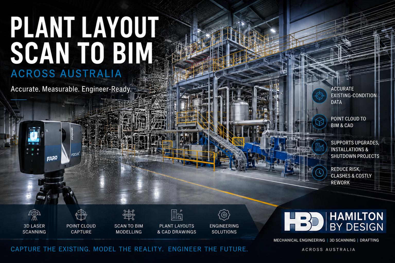
Plant Layout Scan to BIM Australia showing a FARO 3D laser scanner inside an industrial plant with point-cloud and BIM model overlays.

Plant Layout Scan to BIM Australia

Engineering-Grade 3D Laser Scanning for Accurate Existing Plant Layouts

Industrial plants, factories and processing facilities rarely remain exactly as they were originally designed.

Equipment is replaced. Conveyors are extended. Pipework is rerouted. Platforms are added. Production lines change. Structural steel is modified. New services are installed around existing machinery.

Over time, the physical plant can become significantly different from the drawings available to engineers and project teams.

Hamilton By Design provides Plant Layout Scan to BIM services across Australia, combining engineering-grade 3D LiDAR scanning, point-cloud processing and 3D modelling to create accurate representations of existing industrial facilities.

The objective is not simply to produce a visual model. It is to create reliable existing-condition information that can support plant upgrades, machinery installation, production-line modifications, shutdown planning and brownfield engineering.

For broader building, infrastructure and industrial applications, our Scan to BIM Australia services provide a national reality-capture-to-digital-model workflow.


The Biggest Problem: The Plant Has Changed but the Layout Has Not

One of the most common problems in brownfield engineering is the reliability of existing drawings.

A facility may have been operating for 10, 20 or 30 years while undergoing dozens of individual modifications.

These changes may involve:

  • production equipment;
  • conveyors;
  • process machinery;
  • pipework;
  • pumps and valves;
  • structural steel;
  • platforms and walkways;
  • cable trays;
  • ducting;
  • electrical services;
  • equipment foundations; and
  • maintenance access.

Not every modification is accurately incorporated into the original plant-layout drawings.

The result is a significant engineering risk:

A new project can be designed around information that no longer represents what is physically installed.

Plant Layout Scan to BIM helps reduce this uncertainty by capturing the existing facility and creating a measurable digital reference before detailed engineering begins.


What Is Plant Layout Scan to BIM?

Plant Layout Scan to BIM combines 3D laser scanning with digital modelling.

A terrestrial LiDAR scanner records millions of spatial measurements throughout the area of interest. Multiple scanner positions are registered together to create a coordinated 3D point cloud representing the existing plant.

For engineering applications, this point cloud can then be interpreted and converted into useful geometry.

Hamilton By Design’s 3D Laser Scanning for Engineering Projects approach focuses on capturing equipment, structures, conveyors, pipework, floor levels and other interfaces that matter to downstream design.

Depending on the project, the resulting digital plant layout may include:

  • machinery;
  • production equipment;
  • conveyors;
  • tanks and vessels;
  • structural columns;
  • beams and bracing;
  • platforms;
  • pipework;
  • ducting;
  • cable trays;
  • access routes;
  • building geometry; and
  • equipment interfaces.

The level of modelling should be determined by what the project needs to achieve.


Why Accurate Plant Layouts Matter

A plant layout is more than a drawing showing where equipment is located.

For an engineering team, it establishes the relationship between multiple assets and systems.

A new machine may need to fit between an existing conveyor and structural column.

New pipework may need to pass around ducting and cable trays.

A platform may need to provide maintenance access while avoiding existing services.

A conveyor extension may need to align precisely with an existing transfer point.

When these relationships are based on outdated drawings, design uncertainty increases.

An accurate Scan to BIM plant layout gives designers a more reliable basis for answering questions such as:

  • Will the proposed equipment fit?
  • Is sufficient maintenance clearance available?
  • Where are the existing structures?
  • Will the new design clash with existing services?
  • Can equipment be fabricated before a shutdown?
  • Is there sufficient installation access?
  • Which assets may need to be relocated?
  • Where can new pipework or conveyors be routed?

From Point Cloud to Plant Layout CAD

The registered point cloud is the digital record of the existing environment, but many engineering projects require structured CAD geometry.

Hamilton By Design’s Point Cloud to CAD Australia workflow can convert relevant scan information into 2D and 3D engineering geometry for design, fabrication and construction applications.

This can include:

  • plant-layout models;
  • equipment arrangements;
  • general arrangement drawings;
  • structural geometry;
  • mechanical layouts;
  • sections and elevations;
  • equipment interfaces;
  • existing-condition drawings; and
  • design-reference models.

The key is not necessarily to model every object visible in the point cloud.

A successful engineering model captures the information required for the project.


Plant Layout Scanning for Manufacturing Facilities

Manufacturing plants can be particularly challenging because production layouts change continuously.

New machinery may be introduced to increase capacity.

Manual processes may become automated.

Conveyors may be rerouted.

Production cells may move.

New services may be installed around equipment that cannot easily be relocated.

Plant-layout scanning can create a reliable starting point for these modifications.

Hamilton By Design’s broader Manufacturing and Production Engineering capability supports projects involving equipment, production lines, machinery upgrades and existing industrial environments.

Combining that engineering understanding with LiDAR scanning allows the site-capture strategy to focus on the interfaces most important to the proposed modification.


New Equipment Installation

Installing machinery into an existing plant is fundamentally different from designing equipment for an empty building.

The proposed machinery may need to work around:

  • structural columns;
  • production equipment;
  • conveyors;
  • overhead steelwork;
  • pipework;
  • existing foundations;
  • access routes;
  • platforms;
  • electrical services; and
  • maintenance requirements.

Plant Layout Scan to BIM allows the proposed equipment to be evaluated within a model of the existing facility.

This can help identify spatial conflicts before machinery arrives on site.

The aim is straightforward:

Understand the available space before committing to fabrication and installation.


Production-Line and Conveyor Modifications

Production lines often comprise interconnected pieces of equipment.

Changing one machine can affect several others.

A conveyor may need to be extended, shortened, raised or redirected. A new machine may have different inlet and outlet positions. Guarding and operator access may also change.

Scanning the surrounding plant provides a coordinated reference for evaluating these modifications.

A Scan to BIM plant layout can capture:

  • conveyor elevations;
  • centre lines;
  • supports;
  • transfer locations;
  • machinery interfaces;
  • surrounding structures;
  • platforms;
  • access areas; and
  • existing obstructions.

This information can then support design development before the physical modification begins.


Brownfield Plant Engineering

Brownfield engineering means designing around what already exists.

This can make comparatively small projects surprisingly complex.

An existing facility may contain undocumented modifications, legacy equipment, congested services and structures constructed at different stages of the plant’s life.

Hamilton By Design’s Mechanical Engineering Consulting services can use reality-capture information as part of the engineering process for plant modifications, equipment upgrades and industrial projects.

The combination of site capture and engineering allows designers to work from a more complete understanding of the existing environment.


Scan Before the Shutdown

Industrial shutdowns are often short, carefully scheduled and expensive.

Where possible, scanning the plant before a shutdown allows engineering to progress while the facility remains operational.

A typical workflow may involve:

Site Planning

โ†“

3D LiDAR Scanning

โ†“

Point-Cloud Registration

โ†“

Plant Layout Modelling

โ†“

Engineering Design

โ†“

Drawing Development

โ†“

Fabrication Planning

โ†“

Shutdown Installation

This can shift a significant amount of engineering activity away from the shutdown window.

The objective is to identify potential fit-up and interface problems while there is still time to resolve them.


Plant Layout Drawings and Engineering Documentation

A BIM or point-cloud model may be only one component of the final project deliverables.

Many plant modifications still require conventional engineering drawings for fabrication, installation and approval.

Hamilton By Design’s Mechanical Drafting Australia services can support the development of plant layouts, equipment arrangements, general arrangements, sections, elevations and fabrication documentation.

This creates a logical workflow from measured reality through to engineering documentation:

Existing Plant โ†’ LiDAR Scan โ†’ Point Cloud โ†’ CAD/BIM โ†’ Engineering โ†’ Drawings


Scan to BIM for Industrial Plants

Complex industrial facilities can contain machinery, structures, materials-handling systems and services within heavily congested environments.

In these circumstances, measuring only individual dimensions may not provide sufficient context for future engineering decisions.

A coordinated point cloud captures the relationship between multiple assets.

For mining, processing and heavy-industrial environments, Hamilton By Design also provides Scan to BIM for Mining and Industrial Facilities, extending the same reality-capture principles to complex plant and infrastructure.


Typical Plant Layout Scan to BIM Deliverables

Deliverables can be tailored to the downstream engineering requirement and may include:

  • registered point clouds;
  • E57 files;
  • RCP/RCS datasets;
  • LAS point clouds;
  • BIM models;
  • IFC models;
  • SolidWorks models;
  • STEP geometry;
  • SAT geometry;
  • AutoCAD DWG files;
  • DXF drawings;
  • equipment layouts;
  • general arrangement drawings;
  • sections and elevations;
  • structural layouts;
  • existing-condition plans; and
  • interface models.

The most appropriate deliverable depends on whether the project requires general spatial coordination, detailed design, fabrication or long-term asset documentation.


Engineer-Led Plant Layout Scanning

Not every part of a facility needs to be captured or modelled to the same level of detail.

Before scanning begins, it is useful to understand:

  • What is being changed?
  • Which interfaces are critical?
  • What equipment will be installed?
  • What structures affect the design?
  • Does fabrication need to occur before installation?
  • What level of accuracy is required?
  • What CAD or BIM environment will be used?
  • Which areas need detailed modelling?
  • What information is required for future project stages?

Hamilton By Design’s broader Engineering Services combine mechanical engineering, reality capture, modelling and drafting so the scanning and modelling scope can be developed around practical project outcomes.


Plant Layout Scan to BIM Across Australia

Hamilton By Design provides Plant Layout Scan to BIM and engineering-grade 3D laser scanning for industrial projects across Australia.

Typical applications include:

  • manufacturing facilities;
  • food and beverage plants;
  • FMCG facilities;
  • processing plants;
  • mining facilities;
  • warehouses;
  • materials-handling plants;
  • water and wastewater facilities;
  • heavy manufacturing;
  • bulk-material handling;
  • production facilities; and
  • other brownfield industrial environments.

Projects can range from a single machinery installation through to the capture of larger production areas and complete plant environments.


Frequently Asked Questions

What is Plant Layout Scan to BIM?

Plant Layout Scan to BIM uses 3D LiDAR scanning to capture an existing industrial facility and convert the measured point-cloud information into BIM, CAD or engineering models representing the actual plant layout.

Why scan a plant if drawings already exist?

Existing drawings are valuable, but facilities often change over time. Scanning provides a way to verify the installed condition before new engineering is developed.

Can machinery and conveyors be included?

Yes. Equipment, conveyors, structures, platforms, pipework and surrounding building geometry can be captured where relevant to the project.

Can the scan be used for equipment installation?

Yes. One of the main applications is evaluating new machinery within the existing plant environment before fabrication and installation.

Can plant-layout scanning help with shutdown projects?

Yes. Scanning before a shutdown can allow modelling, engineering and fabrication planning to progress before the installation window begins.

Can point-cloud data be converted to CAD?

Yes. Relevant geometry can be interpreted from the point cloud and developed into CAD models, drawings and engineering layouts.

Is Plant Layout Scan to BIM suitable for factories?

Yes. Manufacturing, food and beverage, FMCG and production facilities are particularly suitable because equipment layouts frequently evolve over time.

Do you provide Plant Layout Scan to BIM throughout Australia?

Yes. Hamilton By Design supports engineering-grade reality-capture and plant-layout projects across metropolitan, regional and industrial locations throughout Australia.


Planning a Plant Upgrade?

Before designing new machinery, modifying a production line or fabricating equipment around existing plant, establish an accurate understanding of what is physically installed.

Plant Layout Scan to BIM provides engineering teams with a digital representation of the existing facility that can support better-informed design, coordination and installation decisions.

Hamilton By Design combines 3D LiDAR scanning, point-cloud modelling, mechanical engineering and drafting to support plant upgrades and brownfield projects across Australia.

Capture the existing plant. Understand the layout. Engineer the upgrade around reality.


Hamilton By Design logo displayed on a blue tilted rectangle with a grey gradient background

Contact Us – Talk To Us

Name
Would you like us to arrange a phone consultation for you?
Address

Our clients:
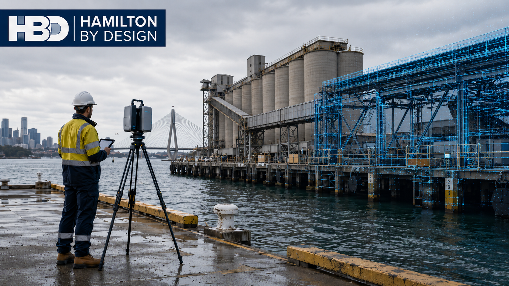


Sydney Marine Facility As-Built Surveys | 3D LiDAR Scanning & Engineering

Sydney marine facility as-built survey using terrestrial laser scanning beside dry-bulk silos, conveyors and wharf infrastructure near the ANZAC Bridge.

Sydney Marine Facility As-Built Surveys โ€“ Accurate Existing-Condition Data for Brownfield Engineering

Sydneyโ€™s marine infrastructure operates in a demanding environment. Wharves, berths, terminals, conveyors, ship-loading systems, pipework, access platforms, structural steel and mechanical equipment may remain in service for decades while undergoing continuous maintenance, modification and upgrading.

One of the greatest challenges for engineers working on these existing facilities is therefore remarkably simple:

Do the drawings accurately represent what is actually there?

In many brownfield marine facilities, the answer may be no.

Original construction drawings can become outdated as equipment is replaced, platforms are modified, services are rerouted, structural members are strengthened and maintenance modifications accumulate over the life of the facility. Different contractors may also produce separate drawing packages, leaving project teams with incomplete or conflicting information.

For engineering projects around Sydneyโ€™s ports, terminals and waterfront industrial facilities, accurate as-built information can therefore become an important foundation for safe, practical and buildable design.

Hamilton By Design provides Sydney Port Engineering Services combining engineering experience with modern reality-capture technology to help establish reliable existing-condition information before brownfield design work begins.

The Problem with Existing Marine Facility Drawings

Engineering drawings represent the design intent at a particular point in time.

Marine infrastructure, however, does not remain unchanged.

A facility that has operated for 10, 20 or 30 years may have undergone numerous modifications including:

  • replacement mechanical equipment;
  • additional structural steel;
  • modified walkways and access platforms;
  • new guards and safety systems;
  • conveyor modifications;
  • altered pipework;
  • electrical and hydraulic services;
  • temporary modifications that became permanent;
  • corrosion repairs and strengthening works;
  • changes completed during shutdowns; and
  • equipment installed by different contractors.

Each individual modification may be relatively small, but collectively they can create a significant difference between the drawing archive and the physical facility.

This becomes particularly important when engineers are designing new equipment that must fit precisely around existing structures.

A few incorrect dimensions can potentially affect an entire fabrication package.

Establishing What Is Actually There

Traditional site measurement remains useful, particularly for individual components and straightforward geometry. However, measuring complex marine infrastructure using tapes, laser distance meters and individual survey points can become difficult when hundreds or thousands of dimensions are required.

Terrestrial LiDAR provides another approach.

Hamilton By Design’s 3D LiDAR scanning and 3D modelling services in Sydney can capture dense spatial information representing visible surfaces throughout an existing facility.

Multiple scanner positions can be registered together to create a coordinated three-dimensional point cloud.

Instead of recording only selected dimensions, the project team can retain a detailed digital record of the accessible existing environment at the time of scanning.

This becomes particularly valuable where design decisions may need to be revisited after the site visit.

Reality Capture for Brownfield Marine Projects

Marine facilities can contain extremely congested areas.

Structural steel, conveyors, chutes, mechanical equipment, pipework, cable trays, hydraulic systems, walkways and handrails may all occupy a relatively small volume.

Understanding these relationships from conventional two-dimensional drawings can be difficult.

Engineering-grade reality capture in Sydney provides a three-dimensional reference that allows designers to examine existing conditions from multiple viewpoints.

The point cloud can assist engineers in understanding:

  • equipment position;
  • structural interfaces;
  • available clearances;
  • access constraints;
  • floor and platform levels;
  • pipe routes;
  • surrounding obstructions;
  • connection locations; and
  • potential installation pathways.

The objective is not simply to create an impressive three-dimensional image.

The real value comes from using measured spatial information to support engineering decisions.

From Point Cloud to Engineering CAD

A point cloud is fundamentally a measurement dataset.

For many engineering projects, it needs to be converted into a form that designers, engineers and fabricators can use efficiently.

Through Point Cloud to CAD Services in Sydney, relevant existing geometry can be reconstructed into CAD models and engineering drawings.

Importantly, not every object within the scan necessarily needs to be modelled.

The appropriate level of modelling should depend on the purpose of the project.

For example, a conveyor modification might require accurate modelling of:

  • existing conveyor structure;
  • pulley positions;
  • transfer chute interfaces;
  • walkways;
  • surrounding structural steel;
  • equipment supports; and
  • potential clash zones.

Modelling unrelated objects elsewhere in the facility may provide little engineering benefit.

A fit-for-purpose approach can therefore keep the model focused on the information required for the engineering task.

Reducing Brownfield Design Uncertainty

One of the largest risks in brownfield engineering is designing new equipment around assumed existing conditions.

An engineering drawing may indicate that two columns are parallel.

The actual structure may have moved slightly.

A nominal platform level may differ from its measured position.

Pipework may have been rerouted.

A conveyor guard may have been added.

A structural brace may occupy the same location proposed for a new component.

This is where combining site capture with practical mechanical engineering services in Sydney becomes particularly useful.

Rather than separating measurement completely from engineering, the capture strategy can be developed around the downstream design problem.

Critical interfaces can be deliberately captured so the resulting dataset supports the decisions that engineers will later need to make.

Supporting Fabrication and Installation

For marine infrastructure projects, fabrication may occur many kilometres away from the operating facility.

Structural steel, platforms, chutes, guards, brackets, pipe supports and mechanical assemblies may be manufactured in a workshop before being transported to site.

Once fabrication begins, dimensional errors become increasingly expensive to correct.

If existing geometry has been incorrectly documented, the problem may only become apparent when the fabricated component reaches site.

The consequences can include:

  • cutting and reworking fabricated steel;
  • modifying holes or mounting plates;
  • additional welding;
  • redesign;
  • additional crane or access requirements;
  • installation delays;
  • extended shutdown work; and
  • additional engineering and fabrication costs.

For this reason, 3D laser scanning for industrial plants in Sydney can also be highly relevant to marine terminals where mechanical plant, materials-handling equipment and structural systems interact.

The aim is straightforward: obtain better information before committing to fabrication.

Reverse Engineering Existing Marine Equipment

Another challenge arises when the equipment itself has incomplete documentation.

Older marine plant may have been modified repeatedly, while original manufacturing drawings may no longer be available.

This can occur with:

  • chutes;
  • guards;
  • covers;
  • hoppers;
  • housings;
  • platforms;
  • mechanical frames;
  • conveyor components; and
  • specialised maintenance equipment.

In these situations, reverse engineering using 3D scanning can establish the geometry of an existing component or assembly as the starting point for replacement, redesign or modification.

The scan is not necessarily the finished engineering deliverable.

Engineering judgement is still required to determine design intent, material requirements, manufacturing methods, tolerances, interfaces and suitable drawing detail.

Marine Infrastructure Is Particularly Suited to Retrofit Scanning

Marine terminals are fundamentally brownfield environments.

The challenge is often not designing something completely new. It is introducing something new into an operating facility that already contains decades of infrastructure.

This makes LiDAR scanning for industrial retrofit engineering particularly applicable to wharf and port projects.

Typical applications may include:

  • conveyor replacement;
  • transfer chute upgrades;
  • walkway modifications;
  • machine guarding;
  • equipment replacement;
  • pipework alterations;
  • structural strengthening;
  • access improvements;
  • maintenance-platform design;
  • services coordination; and
  • installation planning.

In each case, accurate understanding of the existing environment reduces the number of assumptions entering the design process.

Access and Operational Constraints

Marine facilities also present practical surveying challenges.

Some equipment may be elevated, positioned close to water, located around active conveyors or accessible only during controlled operational windows.

Terrestrial laser scanning can capture substantial amounts of visible geometry from each scanner position, reducing the need to physically measure every individual element.

However, LiDAR is a line-of-sight technology.

Objects hidden behind equipment, cladding or structural members cannot automatically be captured from a single scanner position.

A good survey therefore requires planning.

Multiple scan positions may be needed to minimise occlusion, while critical interfaces should be identified before scanning begins.

In some cases, conventional measurement, survey control or supplementary inspection may still be required.

The objective should always be a dataset appropriate for the engineering decisions that depend upon it.

Typical As-Built Deliverables

The final deliverable should be selected according to the project rather than treating every scan as identical.

Depending on requirements, a Sydney marine facility as-built survey may support production of:

  • registered point-cloud data;
  • E57, RCP, RCS or other project-compatible point-cloud formats;
  • AutoCAD drawings;
  • 2D plans and elevations;
  • SolidWorks or other 3D CAD models;
  • structural and mechanical layouts;
  • existing-condition models;
  • equipment-interface geometry;
  • fabrication drawings;
  • clash-review models; and
  • engineering documentation.

The important question is not simply, โ€œWhat can be produced from the scanner?โ€

The more useful question is:

โ€œWhat information does the engineering team need to make the next project decision confidently?โ€

That should determine the survey and modelling strategy.

Creating a Reliable Engineering Baseline

For many Sydney marine projects, the greatest value of an as-built survey is the creation of a defensible engineering baseline.

Instead of beginning a brownfield project with assumptions based on ageing drawings, engineers can begin with measured information representing accessible existing conditions.

The workflow becomes:

Capture the existing facility โ†’ register and review the point cloud โ†’ identify critical interfaces โ†’ develop engineering geometry โ†’ design the modification โ†’ review clashes โ†’ produce drawings โ†’ fabricate โ†’ install.

This does not remove every risk associated with brownfield construction.

It does, however, address one of the most fundamental sources of uncertainty:

not knowing accurately what is already there.

For Sydney wharves, terminals and marine facilities, establishing that information early can support better design decisions, more reliable fabrication and more efficient site installation.

Frequently Asked Questions

What is a marine facility as-built survey?

A marine facility as-built survey records the existing physical configuration of infrastructure such as wharves, terminals, conveyors, structural steel, equipment, platforms, pipework and related assets.

The information can then be used to support engineering, modification, fabrication, maintenance and asset documentation.

Why aren’t the existing drawings sufficient?

Existing drawings remain valuable, but they may not include every modification made during the operating life of a facility.

An as-built survey allows engineers to compare documented information with current physical conditions rather than assuming the drawings remain completely accurate.

Can LiDAR scan an entire wharf or marine facility?

Large areas can be captured using multiple terrestrial scanner positions. The practical extent depends on site access, visibility, required accuracy and the purpose of the survey.

A scan plan should therefore be developed around the required engineering outcomes.

Can terrestrial LiDAR scan underwater?

No. Conventional terrestrial LiDAR is principally used for visible above-water surfaces.

Submerged infrastructure generally requires other techniques such as hydrographic, sonar or specialist underwater survey methods.

These can be complementary to terrestrial scanning where both above-water and below-water information is required.

Can point-cloud information be converted into CAD?

Yes. Relevant scan geometry can be reconstructed into 2D drawings or 3D CAD models.

The appropriate level of detail should be determined by the project requirements rather than automatically attempting to model every scanned object.

Can scanning help with fabrication?

Yes. Accurate capture of existing interfaces can assist designers producing components that need to fit existing structures and equipment.

This can be particularly valuable for brownfield steelwork, chutes, guards, platforms, pipe supports and mechanical equipment modifications.

Can 3D scanning identify clashes before installation?

Point clouds and derived CAD geometry can be incorporated into design coordination and clash-review workflows.

Proposed equipment can therefore be examined relative to captured existing infrastructure before fabrication or installation.

When should a marine facility be scanned?

Ideally, existing-condition capture occurs early in the engineering process and before detailed design or fabrication begins.

Scanning may also be valuable before shutdowns, major equipment replacements, structural modifications or refurbishment projects.

What parts of a marine facility are suitable for scanning?

Typical applications include wharves, berths, conveyors, transfer stations, chutes, platforms, structural steel, plant rooms, pipework, access systems, mechanical equipment and equipment interfaces.

What is the main advantage of an engineering-led as-built survey?

The benefit is not simply collecting more spatial data.

An engineering-led approach focuses the survey on the dimensions, interfaces, clearances and surrounding geometry that will influence the downstream design.

For brownfield marine projects, that can turn a point cloud from a visual record into a practical engineering resource.

Sydney Marine Facility As-Built Survey Support

Where existing drawings are incomplete, outdated or uncertain, obtaining reliable existing-condition information before commencing detailed engineering can significantly improve the quality of the design process.

Hamilton By Design can support marine, port and industrial projects across Sydney with terrestrial LiDAR scanning, point-cloud processing, 3D CAD modelling, mechanical engineering, reverse engineering and engineering drafting.

The objective is simple:

Establish what is actually there before designing what needs to go there.


Hamilton By Design logo displayed on a blue tilted rectangle with a grey gradient background

Contact Us – Talk To Us

Name
Would you like us to arrange a phone consultation for you?
Address

Our clients:























