Structural Steel Detailing, LiDAR Scanning & Engineering Documentation
Hamilton By Design provides Structural Drafting Perth services for construction, shipbuilding, marine infrastructure, manufacturing, smelting, processing facilities, ports, commercial developments and industrial projects throughout Western Australia.
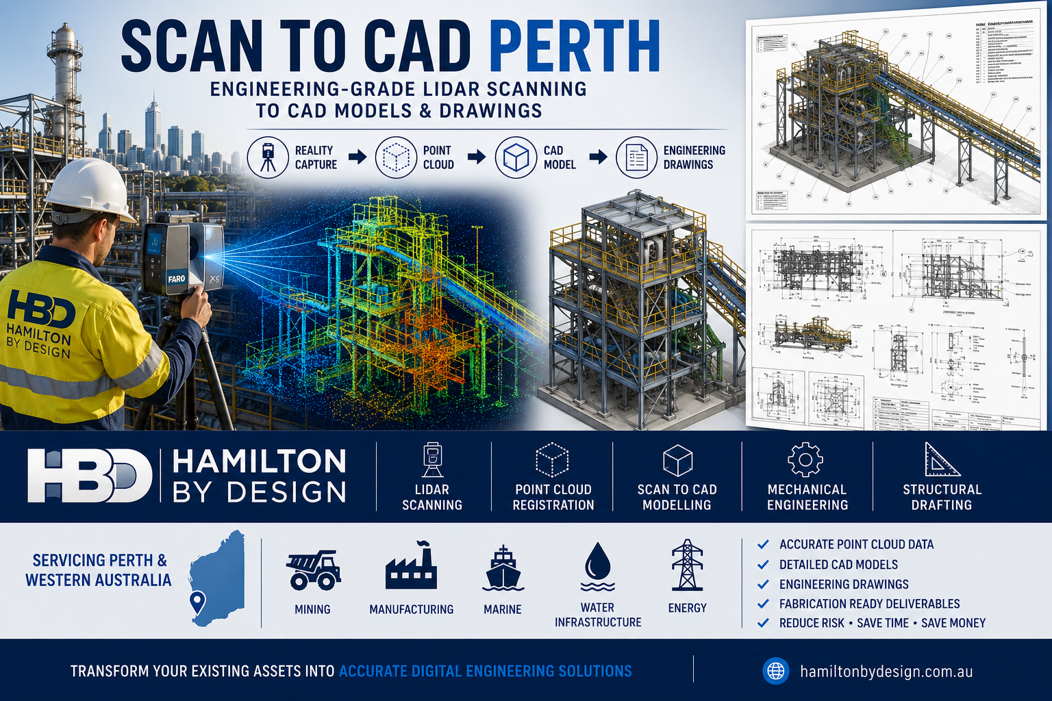
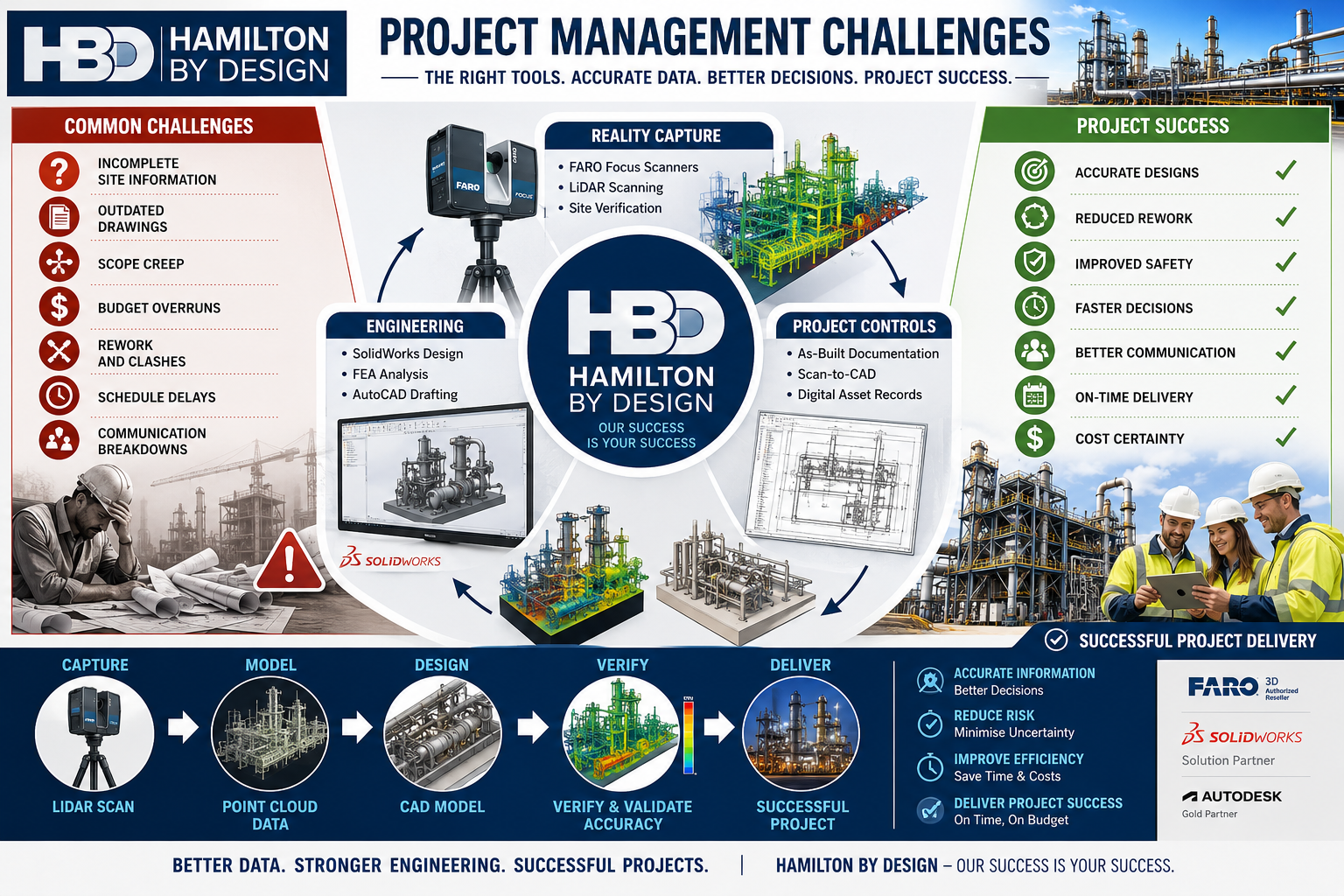
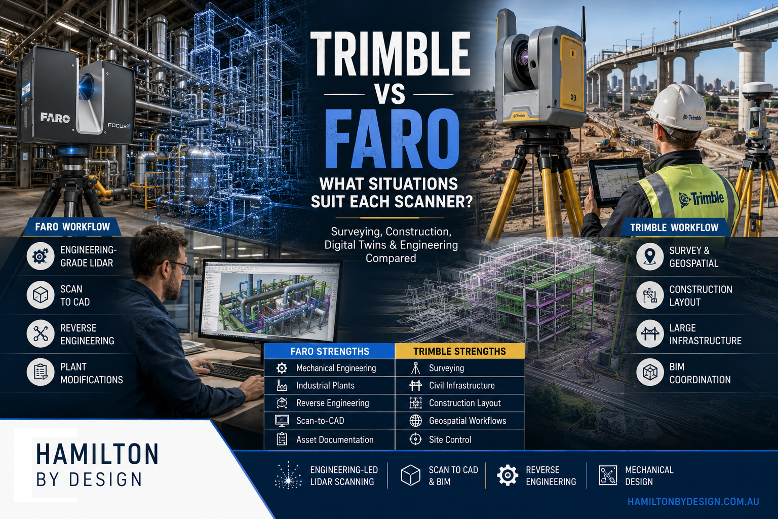
Our team combines engineering-grade LiDAR scanning, 3D CAD modelling, structural drafting, fabrication detailing and digital project management to create accurate engineering documentation for both Greenfield and Brownfield projects.
Whether you are constructing a new facility, modifying an existing plant, expanding a shipyard or upgrading industrial infrastructure, our workflow is designed to reduce site rework, improve constructability and deliver reliable engineering information.
What Is Structural Drafting?
Structural drafting is the process of converting engineering concepts and calculations into detailed drawings and models used for fabrication, construction and installation.
Structural drafting deliverables may include:
- General Arrangement Drawings
- Structural Steel Fabrication Drawings
- Assembly Drawings
- Shop Drawings
- Installation Drawings
- Weld Details
- Bolt Schedules
- Material Take-Offs
- Bill of Materials (BOM)
- As-Built Documentation
- 3D Structural Models
Structural drafting forms the link between engineering design and construction execution.
Industries We Support
Hamilton By Design supports a broad range of industries throughout Perth and Western Australia including:
Construction
- Commercial buildings
- Industrial facilities
- Warehouses
- Hospitals
- Education facilities
- Government infrastructure
Shipbuilding & Marine
- Shipyards
- Wharf upgrades
- Dry dock facilities
- Marine maintenance facilities
- Defence infrastructure
- Port developments
Manufacturing
- Production facilities
- Processing plants
- Packaging facilities
- Material handling systems
Smelting & Processing
- Alumina facilities
- Nickel processing plants
- Lithium processing facilities
- Mineral processing plants
- Industrial processing facilities
Ports & Infrastructure
- Bulk handling facilities
- Conveyor systems
- Transfer stations
- Storage facilities
- Materials handling systems
Energy & Utilities
- Water treatment facilities
- Wastewater infrastructure
- Power generation facilities
- Renewable energy projects
Perth & Western Australia Service Areas
We support projects throughout:
- Perth
- Kwinana
- Henderson
- Fremantle
- Welshpool
- Canning Vale
- Malaga
- Bibra Lake
- Osborne Park
- Joondalup
- Bunbury
- Geraldton
- Kalgoorlie
- Port Hedland
- Karratha
- Pilbara Region
Greenfield Structural Drafting Workflow
Greenfield projects involve new facilities and new infrastructure.
Step 1 – Project Planning
Review:
- Design criteria
- Client requirements
- Applicable standards
- Construction methodology
- Equipment requirements
Step 2 – Concept Development
Develop:
- Facility layouts
- Structural arrangements
- Access systems
- Equipment interfaces
- Maintenance access requirements
Step 3 – Engineering Analysis
Engineering verification may include:
- Wind loading
- Dead loads
- Live loads
- Equipment loads
- Fatigue assessments
- Deflection checks
Step 4 – 3D Structural Modelling
Create digital models for:
- Buildings
- Platforms
- Walkways
- Pipe racks
- Shipyard structures
- Industrial facilities
Step 5 – Structural Drafting
Produce:
- General Arrangements
- Fabrication Drawings
- Assembly Drawings
- Installation Drawings
- Material Schedules
Step 6 – Construction Support
Provide support during fabrication, installation and commissioning.
Brownfield Structural Drafting Workflow
Brownfield projects involve modifications to existing facilities.
These projects typically require verification of existing conditions before engineering and drafting activities begin.
Step 1 – Existing Information Review
Review:
- Existing drawings
- Vendor information
- Historical records
- Asset documentation
Step 2 – LiDAR Scanning & Site Verification
Capture existing conditions using engineering-grade reality capture technology.
Typical assets captured include:
- Structural steel
- Buildings
- Pipework
- Equipment
- Services
- Access systems
Step 3 – Point Cloud Registration
Create registered point clouds and digital site environments.
Step 4 – As-Built Modelling
Develop accurate 3D representations of existing facilities.
Step 5 – Design Development
Design:
- Structural modifications
- New platforms
- Access systems
- Equipment supports
- Pipe bridges
- Facility upgrades
Step 6 – Clash Detection
Identify:
- Structural clashes
- Mechanical clashes
- Installation conflicts
- Access restrictions
Step 7 – Engineering Validation
Verify:
- Existing member capacity
- Connection design
- Foundation impacts
- Equipment loading
Step 8 – Fabrication Detailing
Produce construction-ready documentation for fabrication and installation.
Step 9 – Construction Support
Support contractors and fabricators during project execution.
Step 10 – Final Verification
Create final as-built documentation where required.
Software & Technology
Hamilton By Design utilises industry-leading software and hardware throughout the project lifecycle.
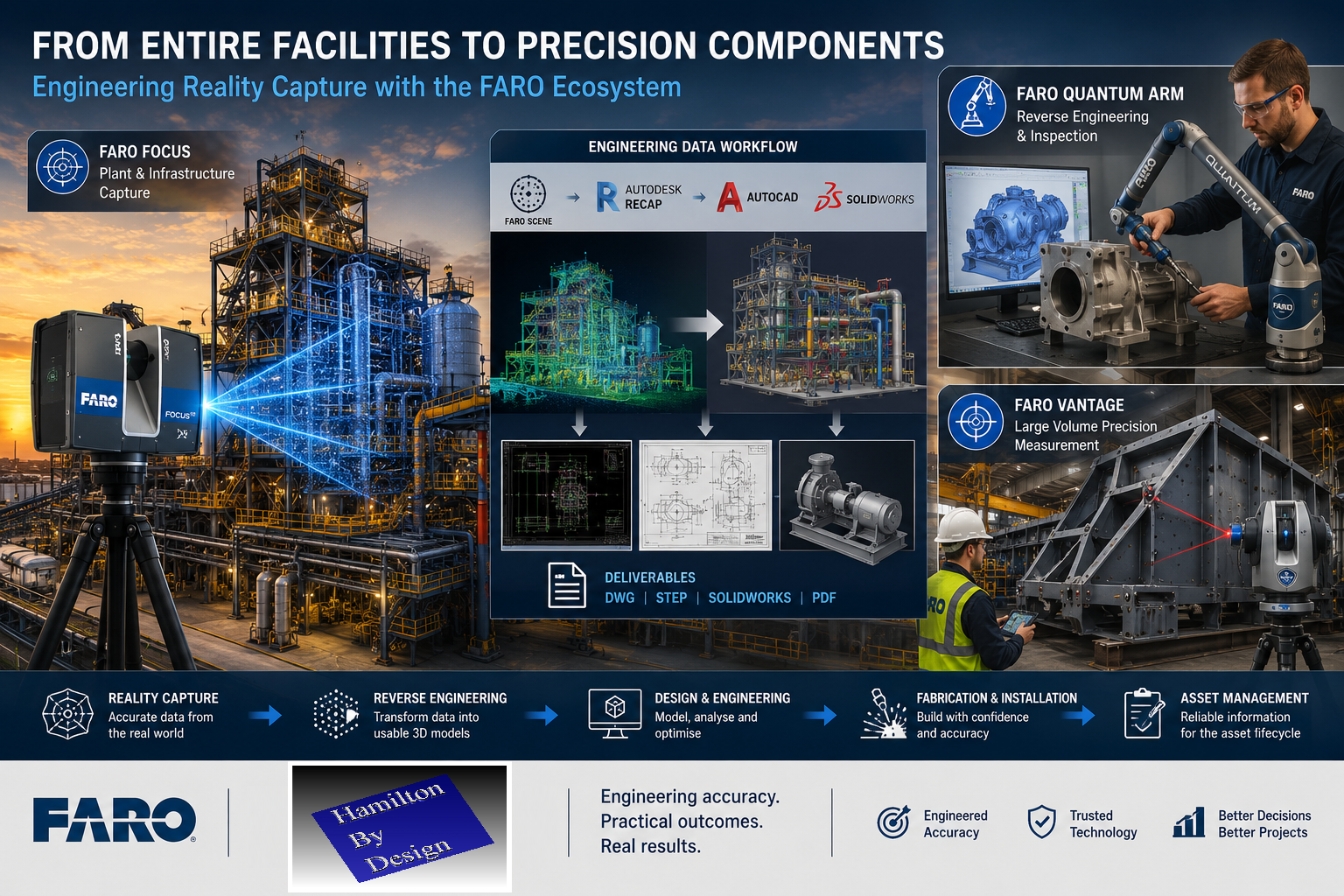
Reality Capture
- FARO Focus S70
- FARO Orbis
- FARO SCENE
- Autodesk ReCap Pro
Design & Drafting
- SolidWorks
- AutoCAD
- Autodesk Inventor
- Revit
Engineering Analysis
- SolidWorks Simulation
- ANSYS
- SPACE GASS
Construction Review
- Navisworks
Data Management & Collaboration
- 3DEXPERIENCE Platform
- ENOVIA
The 3DEXPERIENCE Platform provides centralised project data management, revision control, document management, engineering workflows and collaboration between engineering, drafting, fabrication and construction teams.
Typical Project Deliverables
Depending on project requirements, deliverables may include:
Drawings
- PDF Drawings
- DWG Files
- DXF Files
- General Arrangements
- Fabrication Drawings
- Installation Drawings
3D Models
- STEP Files
- SAT Files
- Parasolid Files
- SolidWorks Models
- Inventor Models
- IFC Models
Reality Capture Data
- E57 Files
- RCP Files
- RCS Files
- LAS Files
Engineering Documentation
- Material Take-Offs
- Bill of Materials
- Design Reports
- As-Built Documentation
Australian Standards Commonly Referenced
Projects may be developed in accordance with applicable standards including:
- AS 1657 Fixed Platforms, Walkways, Stairways and Ladders
- AS 4100 Steel Structures
- AS/NZS 1170 Structural Design Actions
- AS/NZS 5131 Structural Steelwork Fabrication and Erection
- AS 3990 Mechanical Equipment Steelwork
- AS 4991 Lifting Devices
- AS/NZS 4024 Safety of Machinery
Why Hamilton By Design?
Hamilton By Design combines engineering, drafting and reality capture expertise within a single workflow.
Our team can:
- Capture existing conditions using LiDAR scanning
- Create accurate as-built models
- Develop engineering solutions
- Perform structural analysis
- Produce fabrication-ready documentation
- Manage project information using the 3DEXPERIENCE Platform
- Support fabrication and construction activities
- Deliver verified as-built documentation
This integrated approach helps reduce project risk, minimise rework and improve construction outcomes.
Frequently Asked Questions
What is Structural Drafting?
Structural drafting is the preparation of detailed drawings and models used to fabricate and construct structural systems.
What is the difference between Structural Drafting and Structural Engineering?
Structural engineering determines the design requirements, while structural drafting converts the design into construction-ready documentation.
Do you support Brownfield projects?
Yes. Hamilton By Design regularly supports Brownfield upgrades, modifications and expansion projects.
Can LiDAR scanning improve drafting accuracy?
Yes. LiDAR scanning provides accurate existing-condition data that can significantly reduce site rework and clashes.
What software do you use?
We utilise SolidWorks, AutoCAD, Inventor, Revit, ANSYS, SolidWorks Simulation, Navisworks, FARO SCENE, Autodesk ReCap Pro and the 3DEXPERIENCE Platform.
What file formats can be supplied?
DWG, DXF, PDF, STEP, SAT, Parasolid, IFC, E57, RCP, RCS and LAS formats can be supplied depending on project requirements.
Do you provide fabrication drawings?
Yes. We provide fabrication drawings, assembly drawings, installation drawings and material schedules.
Do you support shipbuilding and marine projects?
Yes. We support shipbuilding, marine infrastructure, wharf upgrades and port-related projects throughout Western Australia.

Need Structural Drafting Support?
Whether you’re planning a new facility, upgrading an existing plant, expanding a shipyard, modifying industrial infrastructure or requiring fabrication-ready structural steel drawings, Hamilton By Design can help.
Our team combines engineering-grade LiDAR scanning, 3D modelling, structural drafting and project data management to deliver accurate, constructable solutions.
Our Clients


Speak With an Engineer
Perth Service Area
Hamilton By Design supports structural drafting, LiDAR scanning, Scan-to-CAD, fabrication drawings and engineering projects throughout Perth and Western Australia.
View our Perth service area location on Google Maps:
From Perth CBD to Henderson, Kwinana, Welshpool, Canning Vale, Bibra Lake, Malaga, Fremantle and regional Western Australia, our team provides engineering-led drafting and reality capture solutions for construction, shipbuilding, manufacturing, smelting, ports and industrial infrastructure projects.
Contact us today to discuss your project requirements.