


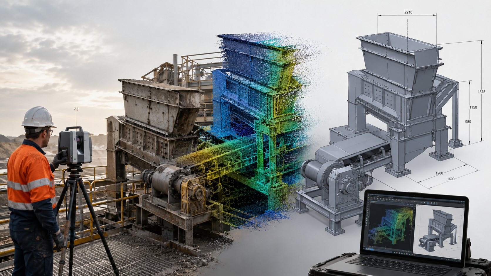
Reverse Engineering and Scan-to-CAD Studies with LiDAR
Existing machinery, plant and fabricated components are often modified over time without the drawings being updated. In other cases, the original manufacturing drawings may be incomplete, inaccurate or no longer available.
Hamilton By Design provides reverse engineering and Scan-to-CAD studies using LiDAR to capture existing assets and convert real-world geometry into practical engineering models and drawings.
Our engineer-led workflow combines 3D laser scanning, point-cloud processing, dimensional verification and CAD modelling. This provides project teams with reliable existing-condition information for equipment replacement, plant modifications, fabrication, refurbishment and brownfield upgrades.
What Is a Reverse Engineering and Scan-to-CAD Study?
A reverse engineering and Scan-to-CAD study involves capturing an existing asset and reconstructing the geometry required for a defined engineering purpose.
This may include:
- recreating machinery where drawings are missing;
- documenting equipment that has been modified;
- developing CAD models for replacement components;
- verifying mounting points and equipment interfaces;
- identifying wear, distortion or dimensional differences;
- preparing models for plant upgrades;
- producing general arrangements and fabrication drawings;
- supporting installation, fit-up and clash checking.
Unlike basic reality capture, the objective is not simply to create a visual representation of the asset. The objective is to produce a fit-for-purpose engineering deliverable that can support design, manufacturing, installation or maintenance decisions.
Our broader reverse engineering 3D scanning service explains how existing assets can be captured and reconstructed without blindly reproducing faults, wear or outdated features.
The Problem with Missing or Inaccurate Drawings
Many industrial assets remain operational long after their original drawings have been lost or become unreliable.
Common problems include:
- original drawings are unavailable;
- drawings do not reflect previous modifications;
- imported machinery has limited documentation;
- replacement parts are no longer manufactured;
- equipment has worn or distorted during service;
- mounting points cannot be confidently measured;
- surrounding plant restricts access for manual measurement;
- replacement equipment must fit during a limited shutdown;
- fabrication begins before site interfaces are properly verified.
When design decisions are based on assumptions, outdated drawings or incomplete measurements, the result can be poor fit-up, fabrication rework, installation delays and additional shutdown costs.
Our engineering-grade 3D laser scanning workflow provides a structured pathway from site capture through to CAD modelling and engineering documentation.
Who Uses Reverse Engineering and Scan-to-CAD Studies?
These studies can support:
- maintenance managers;
- mechanical engineers;
- project engineers;
- reliability engineers;
- asset owners;
- mining and processing operations;
- manufacturers;
- fabrication companies;
- shutdown planners;
- engineering consultants;
- water and wastewater operators;
- infrastructure owners;
- construction contractors.
The service is particularly valuable when a project requires replacement, modification or integration with existing plant but dependable engineering information is not available.
What Can Be Reverse Engineered?
LiDAR scanning and Scan-to-CAD workflows can be used to document a wide range of industrial assets, including:
- conveyors and transfer stations;
- chutes and hoppers;
- screens and crushers;
- machine frames;
- guards and enclosures;
- tanks and vessels;
- pump skids;
- pipework arrangements;
- structural steel;
- platforms and access systems;
- haul-truck bodies and frames;
- production machinery;
- fabricated assemblies;
- equipment bases and mounting arrangements;
- obsolete or custom-built equipment.
For larger plant environments, our point-cloud-to-CAD services can convert captured LiDAR data into useful 2D drawings, 3D models and coordinated engineering information.
How the Study Is Completed
1. Define the Engineering Purpose
Before scanning begins, we establish how the information will be used.
The purpose may be:
- like-for-like replacement;
- equipment redesign;
- fabrication;
- plant modification;
- condition assessment;
- dimensional verification;
- clash detection;
- installation planning;
- refurbishment;
- engineering analysis.
Defining the required outcome helps determine the appropriate scanning method, modelling detail and level of verification.
2. Review Existing Information
Available information is reviewed before attending the site.
This may include:
- existing drawings;
- equipment manuals;
- photographs;
- maintenance records;
- previous CAD models;
- known site modifications;
- required replacement components;
- critical interfaces;
- proposed fabrication methods.
Existing drawings may still provide useful design intent, even when the dimensions need to be confirmed against the actual asset.
3. Capture the Existing Asset
Engineering-grade LiDAR scanning is used to capture the accessible surfaces of the machinery, structure or surrounding plant.
Multiple scan positions may be required to reduce line-of-sight gaps and capture:
- overall equipment geometry;
- mounting locations;
- structural connections;
- adjacent plant;
- pipework;
- access restrictions;
- installation clearances;
- maintenance envelopes;
- floor and foundation levels.
Further information about this process is available on our main 3D laser scanning services page.
4. Verify Critical Dimensions
LiDAR provides a detailed record of the accessible existing geometry. However, critical engineering features may also require verification using traditional measurement or specialised metrology equipment.
Features requiring additional verification may include:
- shaft diameters;
- bearing seats;
- machined faces;
- internal bores;
- bolt threads;
- small hole diameters;
- flange thicknesses;
- inaccessible contact surfaces;
- precision manufacturing tolerances.
The selected measurement method should match the size of the asset, required accuracy and intended use of the final model.
5. Process the Point Cloud
Individual scans are registered and combined into a coordinated point cloud.
The data is then reviewed for:
- coverage;
- alignment;
- unwanted objects;
- movement during scanning;
- reflective surfaces;
- shadowed areas;
- inaccessible geometry;
- required supplementary measurements.
The processed point cloud provides a measurable digital record of the asset and its surrounding environment.
6. Develop the CAD Model
The required geometry is recreated in CAD using the point cloud and verified dimensions as references.
Depending on the project, the deliverable may be:
- a simplified equipment envelope;
- an existing-condition model;
- a detailed solid model;
- an editable parametric model;
- an assembly model;
- a structural layout;
- a general arrangement;
- a replacement component model;
- a fabrication drawing package.
Hamilton By Design also provides AI-assisted Scan-to-CAD services where suitable digital tools can help process high-density point-cloud information. Engineering review remains important because automated tools cannot independently determine design intent, manufacturing requirements or whether existing defects should be reproduced.
7. Validate the Reconstructed Model
The completed model is checked against the point cloud and available physical measurements.
Validation may consider:
- overall dimensions;
- centre lines;
- mounting locations;
- bolt patterns;
- equipment interfaces;
- structural connection points;
- clearances;
- alignment;
- areas of wear or deformation;
- assumptions and inaccessible features.
This step helps distinguish between the geometry directly supported by captured information and geometry that has been reconstructed from engineering judgement.
8. Prepare the Engineering Deliverables
Depending on the agreed scope, deliverables may include:
- registered point-cloud files;
- 3D CAD parts and assemblies;
- STEP or SAT models;
- SolidWorks models;
- AutoCAD drawings;
- general arrangement drawings;
- plans, sections and elevations;
- existing-condition drawings;
- interface and clearance information;
- fabrication drawings;
- dimensional findings;
- identified assumptions and exclusions;
- recommendations for further investigation.
For projects requiring performance assessment, reconstructed geometry can also support engineering analysis and simulation.
Tools Used for Reverse Engineering and Scan-to-CAD
The tools selected depend on the size, complexity and required accuracy of the asset.
Hamilton By Design workflows may include:
- FARO Focus terrestrial LiDAR scanning;
- FARO Orbis mobile reality capture;
- FARO SCENE point-cloud registration;
- Autodesk ReCap point-cloud preparation;
- SolidWorks parts and assembly modelling;
- SolidWorks ScanTo3D tools;
- AutoCAD drafting;
- Autodesk Inventor;
- Navisworks coordination and clash review;
- traditional dimensional measurement equipment;
- specialised metrology scanning where tighter tolerances are required;
- SolidWorks Simulation or ANSYS for subsequent engineering assessment.
LiDAR is generally well suited to large machinery, fabricated structures and complete plant environments. Smaller components or precision-machined features may require a metrology-grade scanner, coordinate measurement equipment or direct physical measurement.
Applications Across Mining and Industry
Mining and Materials Handling
Reverse engineering and Scan-to-CAD studies can support:
- conveyor modifications;
- transfer-chute replacements;
- crusher and screen upgrades;
- haul-truck refurbishment;
- pump and piping modifications;
- shutdown planning;
- plant expansion;
- replacement of obsolete equipment.
Our Hunter Valley mining engineering and scanning services support mining infrastructure, coal handling and preparation plants and materials-handling projects.
Manufacturing
Manufacturing applications may include:
- obsolete machine components;
- imported machinery without usable drawings;
- production-line modifications;
- machine guarding;
- tooling and fixtures;
- custom-fabricated equipment;
- replacement machine frames;
- equipment relocation.
Water and Infrastructure
Scan-to-CAD studies can assist with:
- pump station upgrades;
- treatment-plant modifications;
- existing pipework documentation;
- equipment replacement;
- structural support design;
- access and maintenance improvements;
- brownfield infrastructure projects.
Industrial and Brownfield Facilities
Industrial facilities frequently contain machinery and structures that have been progressively modified.
Our industrial plant 3D scanning services help capture existing plant geometry before new equipment, structural steel or mechanical systems are designed.
Why Use an Engineer-Led Scan-to-CAD Workflow?
Scanning equipment can collect a large quantity of dimensional data, but successful reverse engineering requires more than operating a scanner.
Engineering input is needed to determine:
- which dimensions are critical;
- which features are worn or damaged;
- whether the existing asset reflects its original design intent;
- what geometry should be retained;
- what geometry should be improved;
- how the replacement will be manufactured;
- how the equipment will be installed;
- which interfaces require tighter verification;
- what assumptions must be documented.
Hamilton By Design combines scanning, mechanical engineering and CAD modelling to produce information suited to practical project outcomes.
Benefits of LiDAR Reverse Engineering
A structured LiDAR and Scan-to-CAD study can help:
- reduce reliance on outdated drawings;
- minimise repeated site visits;
- improve design confidence;
- identify site constraints earlier;
- improve replacement-equipment fit-up;
- reduce fabrication rework;
- support remote engineering teams;
- improve shutdown preparation;
- document existing modifications;
- preserve information about legacy assets;
- create an accurate basis for future engineering.
Service Locations
Hamilton By Design provides engineering-led scanning and Scan-to-CAD services across Australia, including:
- Sydney;
- Central Coast;
- Newcastle;
- Hunter Valley;
- Brisbane;
- Perth;
- Melbourne;
- Adelaide;
- Darwin;
- Mount Isa;
- regional and remote mining locations.
Location-specific support is also available through our 3D scanning services in Sydney and 3D LiDAR scanning services in Perth.
Talk to Hamilton By Design
When existing drawings are missing, outdated or unreliable, Hamilton By Design can capture the actual asset and develop a practical engineering model for the next stage of the project.
Our reverse engineering and Scan-to-CAD studies can support equipment replacement, refurbishment, modification, fabrication, installation planning and brownfield plant upgrades.
Contact Hamilton By Design to discuss:
- the asset being investigated;
- the required engineering outcome;
- available drawings and documentation;
- critical dimensions and interfaces;
- site access;
- preferred CAD formats;
- required drawings or models;
- project and shutdown timeframes.
Frequently Asked Questions
What is Scan-to-CAD?
Scan-to-CAD is the process of converting 3D scan or point-cloud data into usable CAD geometry.
The final deliverable may be a 2D drawing, simplified 3D model, detailed solid model, surface model, equipment envelope or complete assembly, depending on the project requirements.
What is the difference between 3D scanning and reverse engineering?
3D scanning captures the visible geometry of an existing asset.
Reverse engineering interprets that captured geometry and uses it to recreate a component, machine or assembly for a specific engineering purpose. This may involve identifying design intent, correcting wear, defining material thicknesses and recreating features that cannot be directly scanned.
Can LiDAR produce a fabrication-ready CAD model automatically?
LiDAR produces a point cloud rather than a completed fabrication model.
The point cloud must be processed and interpreted before suitable CAD geometry can be created. Automated and AI-assisted tools may accelerate parts of the workflow, but engineering review is still required to confirm interfaces, manufacturing requirements, tolerances and design intent.
How accurate is LiDAR Scan-to-CAD?
Accuracy depends on several factors, including:
- the selected scanner;
- scanning distance;
- surface condition;
- line of sight;
- point density;
- registration method;
- environmental conditions;
- modelling method;
- required deliverable.
The required accuracy should be agreed before scanning. Precision-machined features may require supplementary measurement using metrology equipment or traditional inspection tools.
Can you recreate machinery when no drawings exist?
Yes. Existing machinery can often be captured and reconstructed using a combination of 3D scanning, physical measurement, photographs and engineering interpretation.
The achievable result depends on access to the asset, whether components can be removed and whether internal or hidden features need to be recreated.
Can worn components be reverse engineered?
Yes, but the worn geometry should not necessarily be copied directly.
The study may need to identify the likely original geometry, compare symmetrical or unworn areas, review mating components and apply engineering judgement before developing the replacement model.
Can you identify deformation from a LiDAR scan?
LiDAR data may help identify visible deformation, misalignment or dimensional variation when the captured geometry is compared with a reference model, design surface, previous scan or expected geometric form.
A formal structural or mechanical assessment may require additional engineering investigation and analysis.
Can the point cloud be used directly in SolidWorks?
Point-cloud or mesh information can be referenced during SolidWorks modelling, although the data may need to be cleaned, reduced or converted before it can be used efficiently.
The most suitable workflow depends on the point-cloud size, asset complexity and required model detail.
What CAD formats can be supplied?
Depending on the agreed scope, common deliverables may include:
- SolidWorks parts and assemblies;
- STEP;
- SAT;
- Parasolid;
- DWG;
- DXF;
- Autodesk Inventor files;
- RCP;
- RCS;
- E57;
- LAS.
The preferred formats should be confirmed before modelling begins.
Do you provide fabrication drawings?
Yes. Fabrication drawings can be developed where they form part of the agreed scope.
The drawing package may include general arrangements, component details, sections, elevations, material information, weld details and bills of materials. Additional design verification may be required before a reverse-engineered model is released for fabrication.
Do you scan small components?
Small components can be scanned, but terrestrial LiDAR may not be the most suitable technology for every part.
A handheld scanner, structured-light scanner, laser arm, coordinate measurement machine or direct physical measurement may provide a more appropriate level of detail for smaller or precision-machined components.
Can you scan equipment while it remains installed?
In many cases, yes.
Scanning installed equipment can preserve its relationship with surrounding structures, pipework, foundations and adjacent machinery. However, hidden surfaces and internal features may remain inaccessible unless the equipment is dismantled.
Can reverse engineering support equipment improvements?
Yes. Reverse engineering does not have to result in a like-for-like copy.
The captured information can provide a basis for improving:
- access;
- maintainability;
- guarding;
- wear life;
- structural support;
- fabrication;
- installation;
- component availability;
- operating performance.
Any proposed improvement should be assessed against the project requirements and applicable engineering standards.
How long does a Scan-to-CAD study take?
The timeframe depends on:
- asset size;
- site access;
- scanning complexity;
- required point density;
- available drawings;
- CAD model detail;
- number of components;
- required verification;
- drawing requirements;
- engineering analysis requirements.
A small asset may require a relatively short capture and modelling process, while a complete industrial plant or complex machine assembly may require several stages.
What information is required for a quotation?
Useful information includes:
- photographs of the asset;
- approximate dimensions;
- site location;
- existing drawings;
- required CAD format;
- intended use of the model;
- critical dimensions;
- access restrictions;
- required drawings;
- required accuracy;
- shutdown or delivery dates.
Providing this information helps define the appropriate scanning, verification and modelling scope.

Contact Us – Talk To Us
Our clients:
























