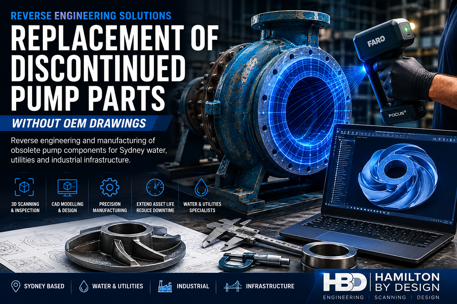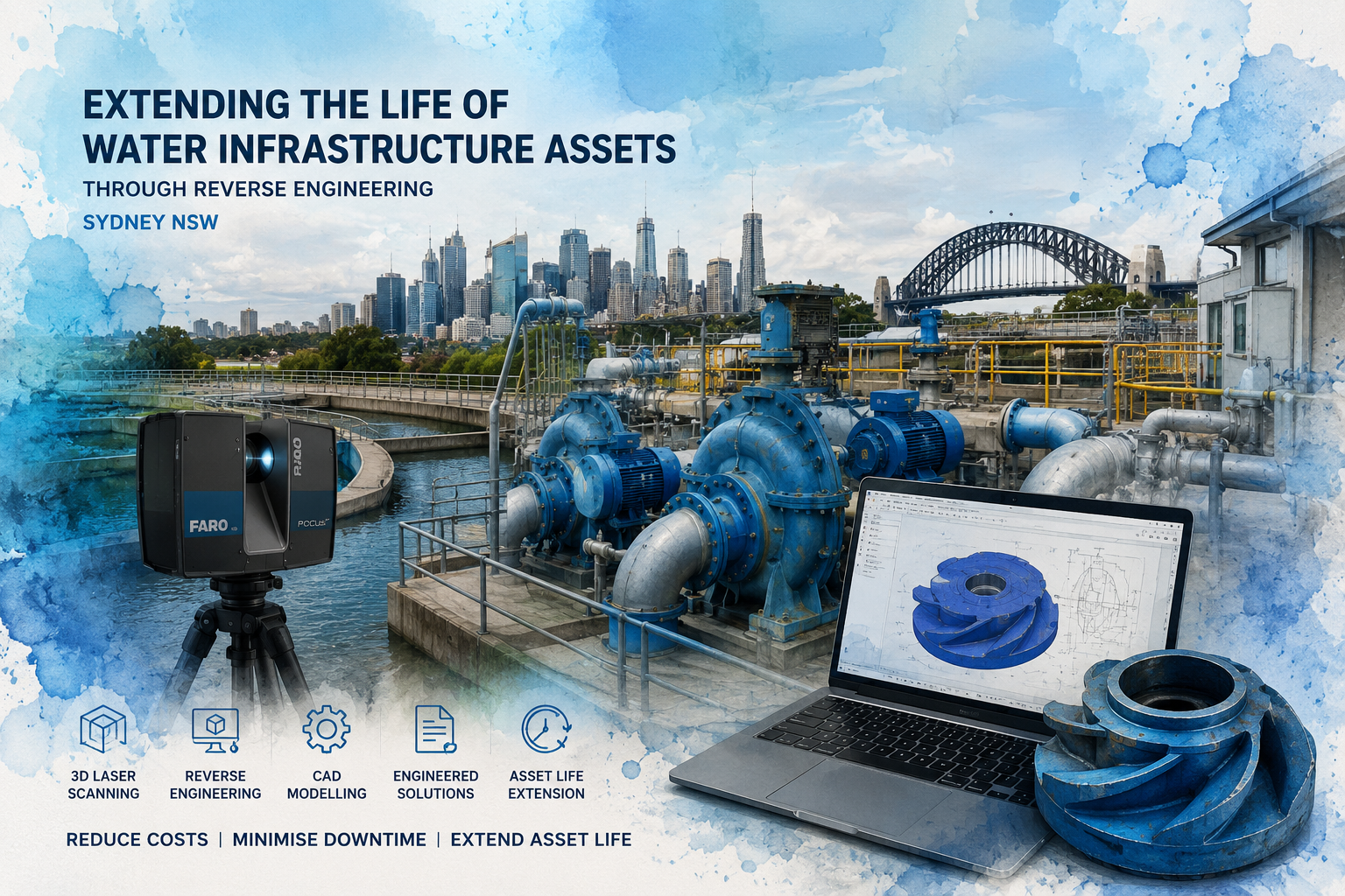
Extend the Service Life of Critical Water Assets Without Full Replacement
Hamilton By Design provides reverse engineering, 3D laser scanning, engineering design, and replacement component manufacturing support for water infrastructure assets throughout Sydney and New South Wales. We help water utilities, local councils, infrastructure owners, treatment plants, pumping stations, and maintenance contractors extend the life of aging equipment when OEM support is unavailable, replacement costs are excessive, or lead times are unacceptable.
Many water and wastewater facilities across Sydney operate assets that have been in service for decades. Pumps, valves, impellers, pipework, mechanical equipment, access systems, and structural components often remain functional but suffer from wear, corrosion, erosion, or obsolescence. In many cases, original drawings no longer exist, suppliers have ceased operations, or replacement parts are no longer manufactured.
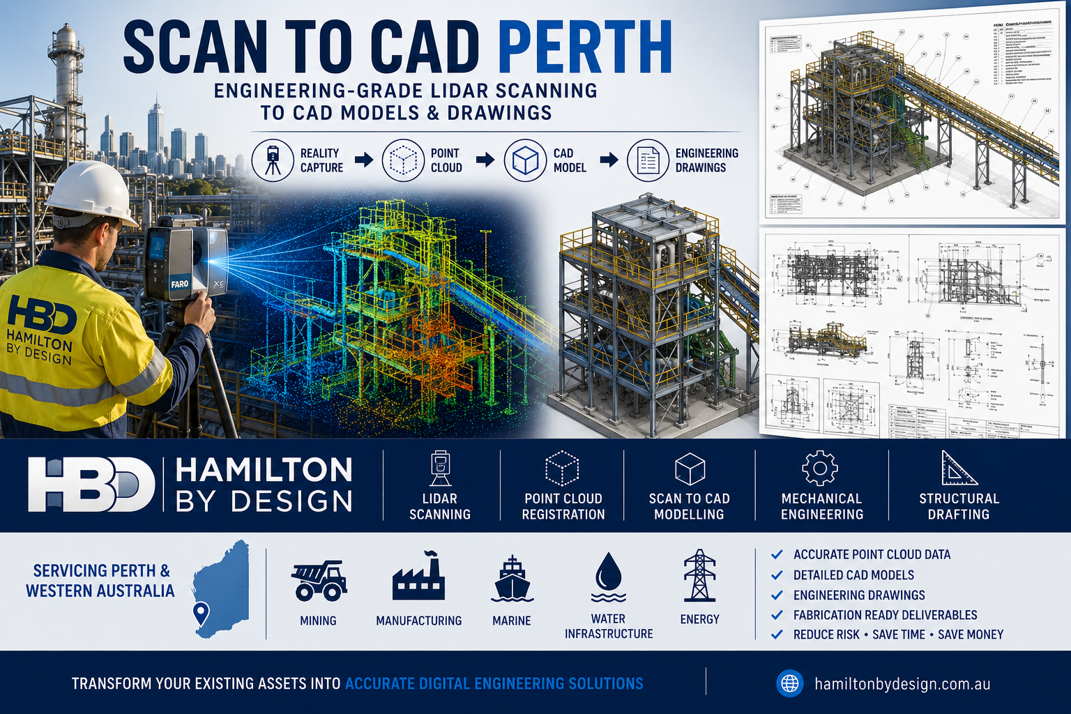
Using engineering-grade 3D laser scanning, reverse engineering, CAD modelling, and manufacturing documentation, we recreate existing assets and produce engineered replacement components that enable continued operation and asset life extension.
Supporting Sydney’s Water Infrastructure
Hamilton By Design supports water infrastructure projects throughout Sydney and regional NSW including:
- Water treatment plants
- Wastewater treatment facilities
- Pumping stations
- Sewage treatment plants
- Stormwater infrastructure
- Water reservoirs
- Water transfer stations
- Desalination facilities
- Council water assets
- Utility infrastructure upgrades
- Brownfield infrastructure projects
- Maintenance shutdowns and asset renewal programs
Our services are suitable for asset owners seeking to maximise the return on existing infrastructure investments while reducing capital expenditure.
Why Reverse Engineering Is Critical for Water Infrastructure
Many water assets remain structurally sound long after spare parts become unavailable.
Common challenges include:
- Discontinued OEM equipment
- Missing engineering drawings
- Obsolete pump models
- Long replacement lead times
- High replacement costs
- Equipment no longer supported by manufacturers
- Limited maintenance documentation
- Corrosion and wear damage
- Asset renewal budget constraints
Rather than replacing an entire system, reverse engineering allows specific components to be recreated and manufactured, significantly reducing downtime and capital expenditure.
This approach can often extend asset life by many years while maintaining operational reliability.
Components Commonly Reverse Engineered
We regularly reverse engineer:
Pump Components
- Impellers
- Pump casings
- Wear rings
- Shafts
- Bearing housings
- Mechanical seal assemblies
- Couplings
- Diffusers
- Pump baseplates
Water Infrastructure Components
- Valve bodies
- Flanges
- Pipe fittings
- Structural supports
- Access platforms
- Mechanical assemblies
- Fabricated steelwork
- Maintenance access systems
- Custom brackets and supports
Treatment Plant Equipment
- Mixer components
- Augers
- Conveyors
- Screens
- Mechanical drives
- Guarding systems
- Process equipment assemblies
Engineering-Grade 3D Scanning for Existing Assets
The first stage of most projects involves capturing accurate field measurements using terrestrial laser scanning.
Hamilton By Design uses:
- FARO Focus Premium Laser Scanners
- FARO Orbis Mobile Scanning Systems
- FARO SCENE Processing Software
- Autodesk ReCap
- SolidWorks
- AutoCAD
- Inventor
Laser scanning captures millions of measurement points from existing assets, creating an accurate digital record of equipment and surrounding infrastructure.
Deliverables may include:
- E57 files
- RCP files
- RCS files
- LAS files
- Registered point clouds
- Scan reports
- Asset condition records
This data becomes the foundation for reverse engineering and future maintenance activities.
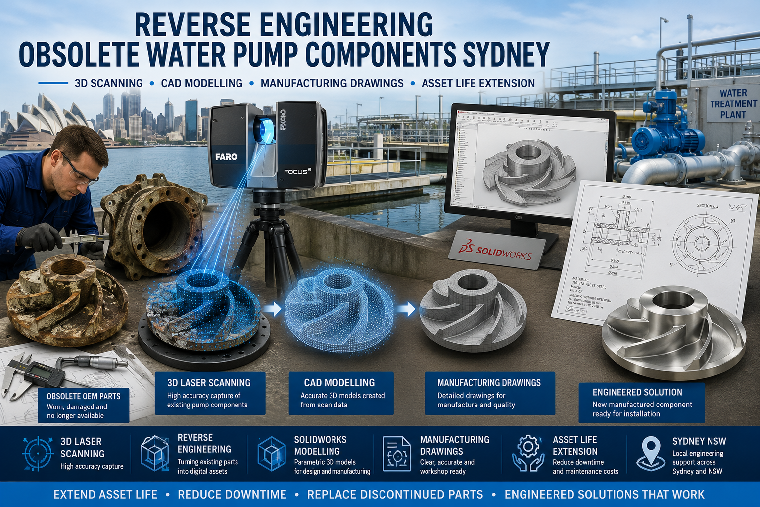
Reverse Engineering Workflow
1. Site Inspection
Our engineers inspect the asset and identify components requiring replacement, modification, or documentation.
2. 3D Laser Scanning
The equipment and surrounding infrastructure are scanned to capture accurate geometry and spatial relationships.
3. Component Assessment
Existing parts are assessed for:
- Wear
- Corrosion
- Damage
- Manufacturing methods
- Functional requirements
4. CAD Modelling
Components are recreated using engineering CAD software.
Models may include:
- Individual components
- Assemblies
- Mechanical interfaces
- Structural elements
5. Engineering Verification
Designs are reviewed and validated to ensure fit, function, and manufacturability.
Where required, engineering calculations and Finite Element Analysis (FEA) can be performed.
6. Manufacturing Documentation
Detailed drawings are produced for fabrication or machining.
7. Manufacturing Support
Documentation is supplied to approved manufacturers for production of replacement components.
Asset Life Extension Benefits
Reverse engineering provides significant advantages for water infrastructure operators.
Reduced Capital Expenditure
Avoid replacing complete systems when only specific components have failed.
Reduced Downtime
Manufacture replacement parts without waiting for OEM support.
Improved Asset Knowledge
Generate accurate engineering documentation for future maintenance.
Improved Reliability
Replace worn or damaged components with engineered solutions.
Future-Proof Asset Management
Create digital asset records that support future maintenance and upgrades.
Support for Aging Infrastructure
Extend the useful life of critical water assets while maintaining operational performance.
Typical Deliverables
Clients may receive:
- Registered point clouds
- E57 files
- RCP files
- RCS files
- LAS files
- Scan reports
- Reverse engineered CAD models
- SolidWorks files
- STEP files
- Parasolid files
- DWG drawings
- DXF drawings
- General arrangement drawings
- Manufacturing drawings
- Fabrication drawings
- Assembly drawings
- Bill of Materials (BOM)
- Engineering reports
- FEA reports where required
Industries We Support
Water Utilities
Support for treatment plants, pumping stations, reservoirs, and distribution infrastructure.
Local Government
Asset management and life extension programs for council-owned infrastructure.
Infrastructure Owners
Engineering support for aging mechanical and structural assets.
Wastewater Treatment Facilities
Reverse engineering and replacement component development.
Industrial Water Operations
Support for manufacturing facilities and process plants with critical water infrastructure.
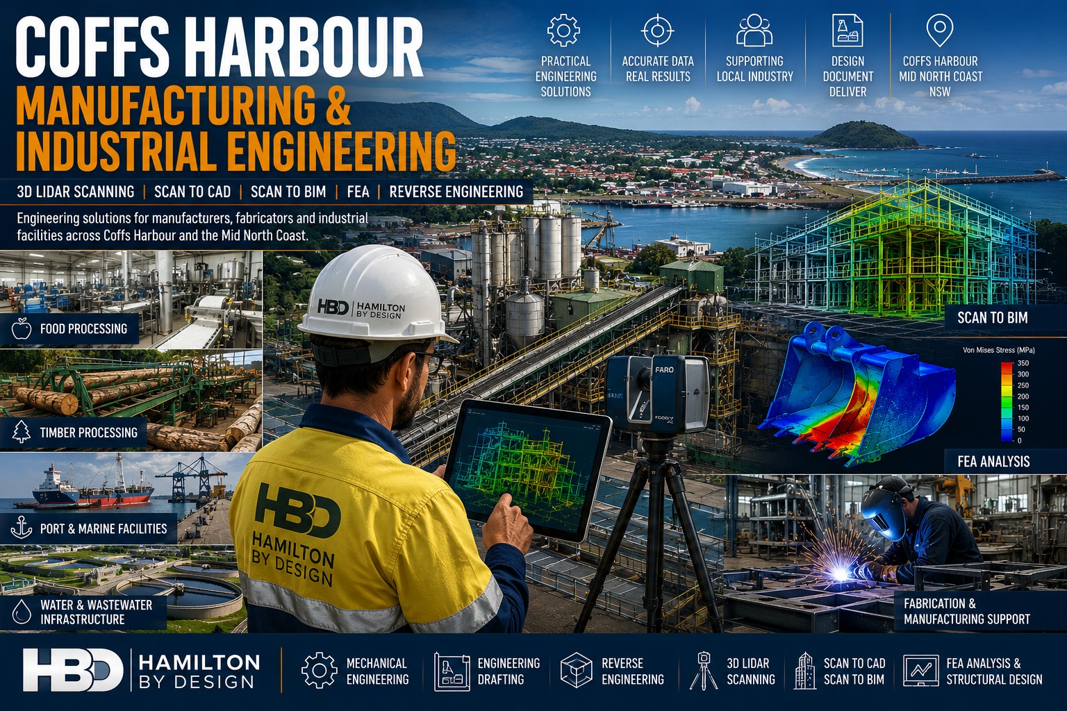
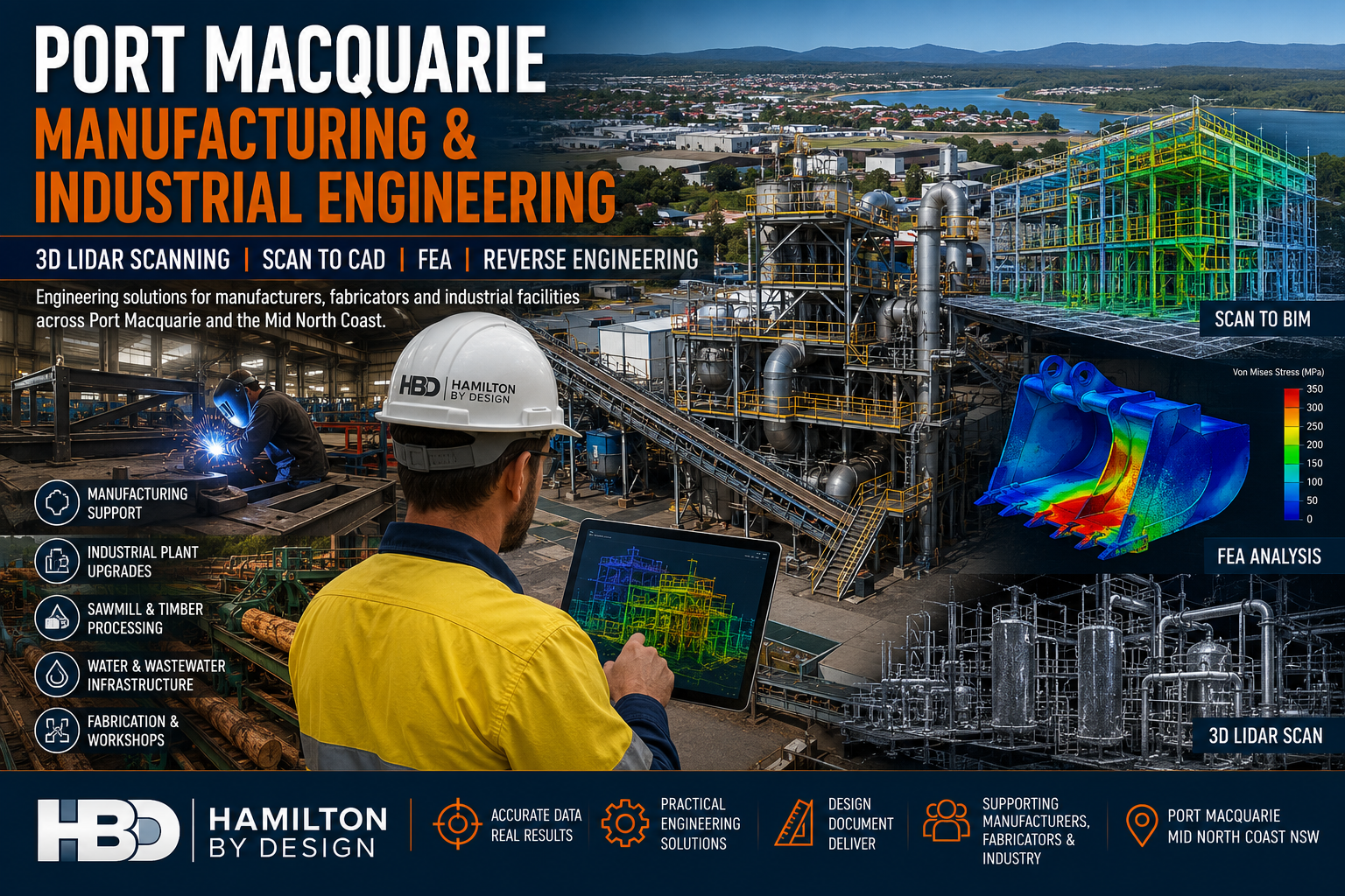
Why Choose Hamilton By Design?
Hamilton By Design combines practical engineering experience with advanced digital capture technology.
Our capabilities include:
- Mechanical Engineering
- Reverse Engineering
- 3D Laser Scanning
- 3D LiDAR Scanning
- Scan to CAD
- Engineering Drafting
- Asset Documentation
- Finite Element Analysis (FEA)
- Manufacturing Support
- Brownfield Infrastructure Engineering
We understand the challenges faced by water utilities operating aging infrastructure and provide practical solutions that reduce costs, minimise downtime, and extend asset life.
Sydney Water Infrastructure Reverse Engineering Services
If your organisation operates aging pumps, treatment equipment, mechanical assets, or infrastructure components that are no longer supported by the original manufacturer, Hamilton By Design can help.
Through reverse engineering, 3D scanning, CAD modelling, and manufacturing documentation, we provide practical asset life extension solutions for water infrastructure across Sydney and New South Wales.
Contact Hamilton By Design today to discuss reverse engineering solutions for obsolete water infrastructure assets, replacement components, and asset life extension projects throughout Sydney NSW.
Talk to Us – Contact Us
Our clients: