FARO Blink: Making Reality Capture Faster, Simpler and More Accessible
The reality capture industry continues to evolve at an incredible pace.
For many years, 3D laser scanning and LiDAR technologies were considered specialist tools used primarily by surveyors, metrology professionals, and engineering teams with extensive training and experience. While the benefits of reality capture were well understood, the technology often required significant expertise, specialised software, and dedicated workflows to achieve successful outcomes.
Today, that is beginning to change.
The introduction of Blink by FARO represents another significant step toward making reality capture more accessible to a wider range of users. Designed to simplify the process of capturing, managing, and sharing digital site information, Blink demonstrates how automation, cloud connectivity, and intuitive workflows are reshaping the way organisations document and understand their physical assets.
For asset owners, facility managers, project teams, engineers, and contractors, the implications are substantial.
The easier it becomes to capture accurate information about the real world, the easier it becomes to make better decisions.
Why Reality Capture Matters
Before discussing Blink specifically, it is worth understanding why reality capture has become such an important part of modern engineering and asset management.
Many industrial facilities were built decades ago.
Over time they undergo:
- Plant modifications
- Equipment upgrades
- Maintenance projects
- Structural alterations
- Utility relocations
- Expansion works
Unfortunately, documentation does not always keep pace with these changes.
Many facilities operate with:
- Incomplete drawings
- Outdated CAD models
- Missing records
- Unknown modifications
- Conflicting documentation
When engineers begin a new project, they often discover that the available information does not accurately reflect existing site conditions.
This creates risk.
Design errors, fabrication clashes, installation delays, and costly rework often result from inaccurate site information.
Reality capture helps solve this problem by creating an accurate digital representation of existing conditions.
Instead of guessing what exists, project teams can work from measured reality.
What is FARO Blink?
Blink by FARO has been developed to simplify the process of reality capture by combining laser scanning hardware, automated processing, cloud-based workflows, and digital collaboration tools.
Rather than requiring users to become experts in registration workflows, point cloud processing, and data management, Blink focuses on creating a streamlined experience that allows information to move quickly from site capture to project insights.
The goal is simple:
Capture reality quickly, process it efficiently, and make the information available to the people who need it.
For many organisations this removes some of the barriers that traditionally prevented them from adopting reality capture technology.
Benefit 1: Faster Site Documentation
One of the biggest advantages of modern reality capture systems is speed.
Traditional site measurement often involves:
- Tape measures
- Hand sketches
- Manual notes
- Laser distance meters
- Photographs
This approach can be time consuming and often requires multiple visits to site.
When information is missed, the team must return to collect additional measurements.
Reality capture dramatically reduces this risk.
By capturing millions of measured points within the environment, teams create a digital record that can be referenced long after the site visit has been completed.
This means:
- Fewer return visits
- Reduced travel costs
- Faster project commencement
- Improved confidence in measurements
For remote sites, mines, ports, power stations, and manufacturing facilities, this benefit alone can provide significant value.
Benefit 2: Improved Project Collaboration
Modern projects often involve multiple stakeholders.
These may include:
- Asset owners
- Engineers
- Contractors
- Draftspersons
- Project managers
- Maintenance teams
- Operations personnel
Historically, communication between these groups relied heavily on drawings, reports, photographs, and site visits.
Reality capture provides a common visual reference that everyone can understand.
Instead of discussing what might exist, project teams can review actual site conditions.
This improves:
- Communication
- Decision making
- Design reviews
- Stakeholder engagement
- Project planning
The result is fewer misunderstandings and more efficient project delivery.
Benefit 3: Better Asset Management
Asset owners increasingly recognise the value of maintaining accurate digital records of their facilities.
Reality capture supports:
- Asset verification
- Facility documentation
- Maintenance planning
- Future upgrades
- Capital works programs
Rather than relying on historical documentation, organisations can maintain current digital representations of their facilities.
This creates a foundation for long-term asset management and digital engineering initiatives.
Benefit 4: Reduced Project Risk
One of the greatest causes of project cost overruns is unexpected site conditions.
Examples include:
- Pipework clashes
- Structural interference
- Equipment access issues
- Missing clearances
- Undocumented modifications
Reality capture helps identify these issues before construction begins.
By working with accurate site information, engineers can identify problems early when they are less expensive to resolve.
This reduces:
- Rework
- Variation claims
- Fabrication errors
- Installation delays
- Safety risks
The result is greater project certainty.
Benefit 5: Supporting Digital Transformation
Many organisations are currently pursuing digital transformation initiatives.
These may include:
- Digital twins
- Asset management systems
- BIM environments
- Digital engineering platforms
- Smart infrastructure programs
Accurate site information forms the foundation of these initiatives.
Without reliable data, digital transformation becomes difficult to achieve.
Reality capture provides the measured information required to build digital representations of physical assets.
This enables organisations to move toward more connected and data-driven operations.
Benefit 6: Easier Adoption of Reality Capture
Historically, one of the challenges associated with laser scanning has been the level of expertise required.
Specialist operators often needed extensive experience with:
- Scanning hardware
- Registration software
- Point cloud management
- Data processing
- Quality control
Automation is helping reduce this complexity.
Systems such as Blink focus on making reality capture easier to deploy and easier to use.
This means more organisations can benefit from digital site documentation without needing to become scanning specialists.
As technology continues to evolve, reality capture is becoming increasingly accessible across industry.
Benefit 7: Enhanced Visualisation
Many people find it easier to understand visual information than technical drawings.
Reality capture provides rich visual context that can support:
- Design reviews
- Stakeholder presentations
- Maintenance planning
- Safety assessments
- Operational discussions
Visual access to site information helps project teams communicate more effectively and make decisions with greater confidence.
Benefit 8: Better Information Retention
Facilities change over time.
Personnel change.
Knowledge is lost.
Documentation becomes outdated.
Reality capture creates a permanent digital record of a facility at a specific point in time.
This information can be referenced years later when:
- Maintenance is required
- Equipment is replaced
- Upgrades are planned
- Incidents are investigated
The value of this historical record often increases over time.
Technology is Only Part of the Solution
While advances such as Blink are making reality capture more accessible, it is important to recognise that technology alone does not solve engineering challenges.
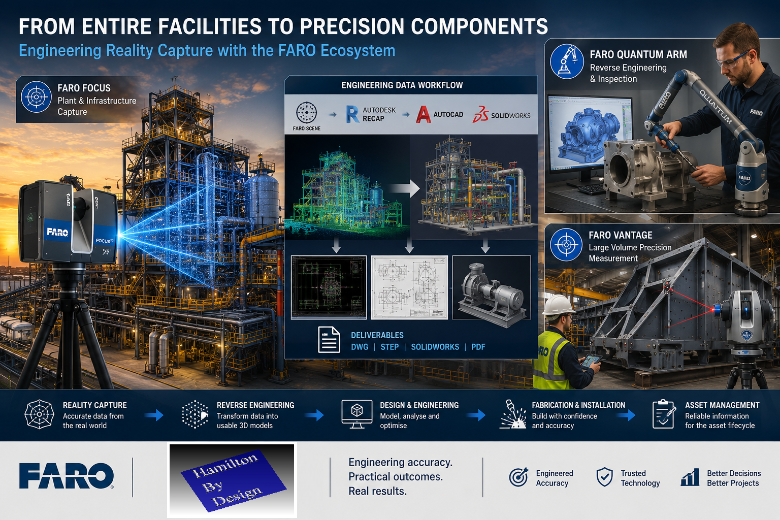
The true value comes from transforming captured information into usable engineering deliverables.
This may include:
- 3D CAD models
- General arrangement drawings
- Fabrication drawings
- Structural models
- Mechanical assemblies
- As-built documentation
- Asset registers
Collecting data is only the first step.
Engineering expertise remains essential for converting information into practical project outcomes.
Where Hamilton By Design Fits In
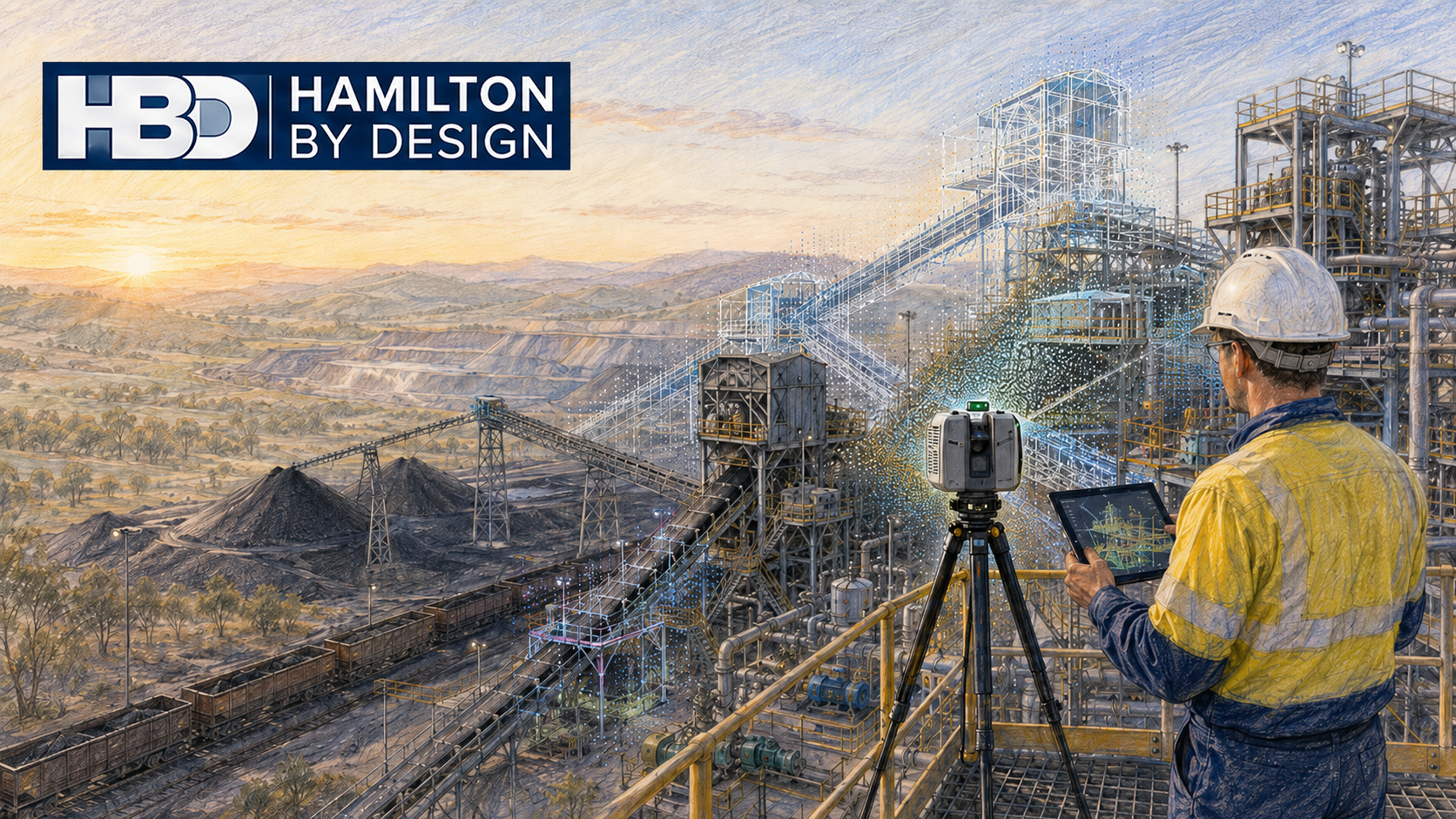
At Hamilton By Design, we view reality capture as part of a broader engineering workflow.
Our objective is not simply to capture data.
Our objective is to help clients make better engineering decisions.
We provide:
- Engineering-grade LiDAR scanning
- 3D laser scanning
- Scan-to-CAD services
- Reverse engineering
- Mechanical engineering
- Structural drafting
- Asset verification
- Digital engineering support
Our team combines decades of experience in engineering, manufacturing, maintenance, drafting, and industrial project delivery.
This means we understand not only how to collect data, but also how that information is ultimately used within engineering projects.
Learn more about our reality capture services:
From Point Clouds to Engineering Outcomes
One of the biggest misconceptions about reality capture is that the point cloud itself is the final deliverable.
In reality, most organisations require outcomes such as:
- CAD models
- Engineering drawings
- Equipment layouts
- Structural modifications
- Fabrication packages
- Asset documentation
At Hamilton By Design, we routinely transform point cloud data into engineering deliverables that support:
- Shutdown planning
- Plant upgrades
- Equipment replacement
- Facility expansions
- Maintenance projects
- Capital works programs
This is where engineering knowledge and reality capture technology come together.
Looking Ahead
The launch of Blink highlights an important industry trend.
Reality capture is becoming:
- Faster
- Simpler
- More automated
- More connected
- More accessible
These developments will continue to expand the adoption of digital site documentation across industry.
For asset owners, facility operators, and project teams, this means better access to accurate information and improved decision making.
For engineering companies, it creates new opportunities to deliver more efficient and more reliable project outcomes.
The future of engineering will increasingly rely on accurate digital representations of the physical world.
Reality capture technologies such as Blink are helping make that future more accessible than ever before.
Explore More
Hamilton By Design supports clients across Australia with engineering-led reality capture and digital engineering services.
Learn more:
Related Articles
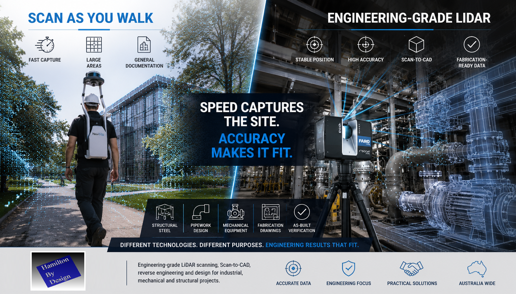
Engineering Grade LiDAR Scanning vs Scan-As-You-Walk Systems
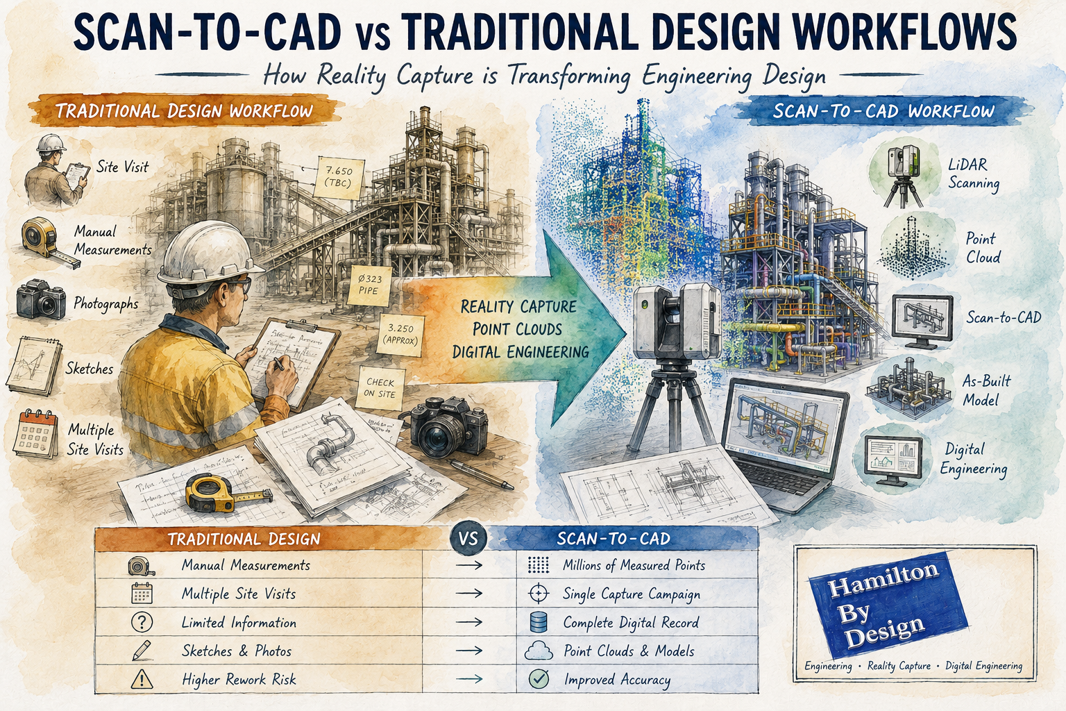
Scan to CAD vs Traditional Design Workflows
SolidWorks Point Cloud to CAD Workflow
Automated Object Recognition from Point Clouds
As reality capture technology continues to evolve, organisations that combine accurate data with engineering expertise will be best positioned to deliver safer, smarter, and more successful projects.