

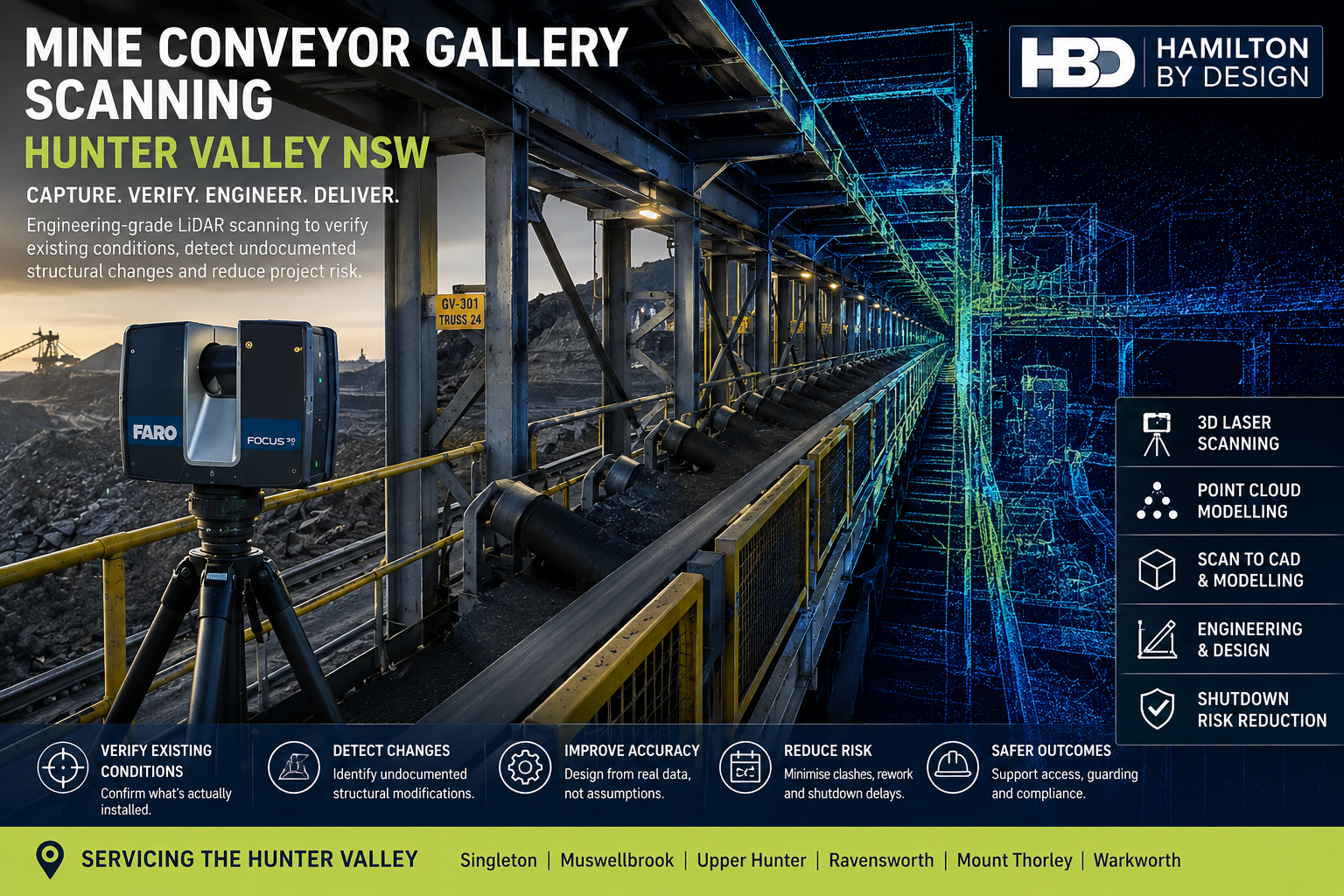
Mine Conveyor Gallery Scanning Hunter Valley NSW | Hamilton By Design

Mine conveyor gallery scanning in the Hunter Valley NSW using engineering-grade LiDAR and point-cloud modelling

Engineering-Grade LiDAR Scanning for Existing Conveyor Structures, Brownfield Upgrades and Shutdown Planning

Mine conveyor galleries are long-life assets that are frequently modified as operating requirements change. Over time, additional bracing may be installed, structural members may be strengthened, walkways altered, guarding replaced, services added and conveyor equipment upgraded.

The challenge is that these modifications are not always fully incorporated into the original engineering drawings.

For project, maintenance and structural engineering teams, this creates a significant source of uncertainty:

Does the available drawing represent the conveyor gallery that is actually installed on site?

Hamilton By Design provides mine conveyor gallery scanning services throughout the Hunter Valley NSW, using engineering-grade terrestrial LiDAR scanning, registered point clouds and CAD modelling to capture the actual existing condition of conveyor galleries and associated mining infrastructure.

The objective is not simply to create a 3D image of the conveyor.

It is to provide reliable engineering information that can be used to verify existing conditions, support structural modifications, reduce fabrication risk and improve shutdown planning.

The Problem: Undocumented Structural Changes

Mine conveyor galleries may operate for decades.

During their service life, structural and mechanical modifications can accumulate through maintenance projects, production upgrades, shutdown work and equipment replacement.

Examples may include:

  • additional structural bracing;
  • replacement beams or columns;
  • strengthened connections;
  • modified conveyor support frames;
  • altered walkways;
  • new access platforms;
  • replacement handrails;
  • additional equipment supports;
  • pipework and service additions;
  • relocated cable trays;
  • modified guarding;
  • changes to conveyor drives or pulleys; and
  • local repairs following corrosion or damage.

The original drawings may remain useful, but they cannot always be assumed to represent the final installed arrangement.

Hamilton By Design’s work with 3D laser scanning for conveyor transfer towers addresses a closely related brownfield problem: conveyors, chutes, steelwork and access structures often evolve over time, creating differences between the physical plant and legacy drawings. (Hamilton By Design Co.)

For conveyor gallery upgrades, those differences can affect every stage from conceptual design through fabrication and installation.

What Risk Does Incorrect Existing Information Create?

The engineering risk is not simply that a drawing contains an incorrect dimension.

The larger issue is that a project may be developed around an incorrect understanding of the existing structure.

Structural Interface Risk

A proposed beam, support or platform may be designed around an assumed connection point that differs from the installed arrangement.

This can result in late redesign or unplanned field modifications.

Fabrication Fit-Up Risk

New steelwork may be fabricated accurately to the design model but still fail to fit because an undocumented brace, support or service occupies the required space.

Shutdown Risk

Unexpected existing conditions may only become apparent once the plant is isolated and installation work begins.

During a short shutdown window, even relatively minor fit-up problems can consume valuable time.

Access Risk

New equipment or structural modifications may interfere with walkways, platforms, guarding or maintenance access.

Scope and Cost Risk

Additional structural work may be discovered after detailed engineering has commenced, potentially affecting project scope, programme and cost.

The purpose of LiDAR scanning is therefore broader than dimensional measurement.

It is a method of reducing uncertainty before design decisions become expensive to change.

Mine conveyor gallery scanning can support:

  • mine owners and operators;
  • engineering managers;
  • project engineers;
  • structural engineers;
  • mechanical engineers;
  • maintenance teams;
  • reliability engineers;
  • shutdown planners;
  • CHPP personnel;
  • conveyor contractors;
  • EPCM organisations;
  • structural steel fabricators; and
  • drafting and modelling teams.

The strongest use case is generally a brownfield project where new work must interface accurately with existing infrastructure.

A structural engineer may need to know the actual position of existing steel before developing strengthening details.

A mechanical engineer may need the conveyor centreline, drive arrangement or equipment envelope.

A fabricator may need confidence that a prefabricated assembly will fit when delivered to site.

All of these requirements depend on reliable existing-condition information.

Terrestrial LiDAR scanning allows conveyor galleries and their surrounding structures to be captured from multiple positions.

The scanner records millions of spatial measurements that collectively describe the visible geometry of the structure.

Typical items captured may include:

  • conveyor trusses;
  • gallery steelwork;
  • trestles and columns;
  • structural bracing;
  • conveyor stringers;
  • idler frames;
  • pulley arrangements;
  • access platforms;
  • stairs and walkways;
  • handrails;
  • guarding;
  • equipment supports;
  • pipework;
  • cable trays;
  • services; and
  • interfaces with transfer towers.

The advantage over isolated field measurements is context.

Rather than measuring only the component thought to be important at the beginning of the project, the scan captures the broader physical relationship between the structure, conveyor equipment and surrounding plant.

Hamilton By Design’s broader 3D laser scanning services specifically address the limitations of outdated as-built drawings and manual measurement in complex industrial environments, where undocumented changes and difficult access can undermine design accuracy. (Hamilton By Design Co.)

Register the Point Cloud

Individual scans are processed and aligned into a registered point-cloud dataset.

This produces a measurable digital representation of the conveyor gallery at the time of capture.

Engineering teams can then inspect and measure the gallery away from site.

Potential measurements include:

  • structural member positions;
  • elevations;
  • conveyor centrelines;
  • beam spacing;
  • column locations;
  • bracing geometry;
  • clearances;
  • walkway widths;
  • platform elevations;
  • equipment offsets; and
  • service locations.

This can substantially reduce the need to return to site every time an additional dimension becomes important during detailed design.

A useful project principle is:

Capture comprehensively on site, then measure selectively during engineering.

Compare Drawings with the Installed Structure

Where legacy drawings are available, LiDAR provides an opportunity to compare documented geometry with actual site conditions.

This may identify:

  • additional structural members;
  • removed members;
  • relocated components;
  • modified platforms;
  • undocumented services;
  • altered support arrangements; and
  • differences in equipment position.

This is particularly important when historical drawings are labelled as-built but have not been comprehensively updated following later modifications.

Hamilton By Design also uses LiDAR for as-built drawings derived from registered point clouds, allowing structural, mechanical and service information to be documented from the physical installed condition rather than relying solely on historic mark-ups. (Hamilton By Design Co.)

For conveyor-gallery projects, the principle is straightforward:

Use the drawing as engineering information, but verify critical interfaces against reality.

From Point Cloud to CAD or BIM

A registered point cloud can often provide sufficient information for measurement and spatial review.

However, some projects benefit from converting selected elements into CAD or BIM geometry.

Depending on the engineering scope, modelling may include:

  • primary structural steel;
  • conveyor centreline;
  • trestles;
  • bracing;
  • walkways;
  • platforms;
  • equipment supports;
  • conveyor equipment; and
  • interfaces with adjacent structures.

The appropriate level of modelling should be determined by the engineering purpose.

There is little value in modelling every nut, bolt and cable if those details do not influence the proposed modification.

For larger engineering and asset-information workflows, Hamilton By Design’s Scan to BIM services for Newcastle and the Hunter support conveyor upgrades, structural modifications, mining assets and brownfield projects using LiDAR capture, point clouds and digital modelling. (Hamilton By Design Co.)

The purpose is to create usable engineering information rather than digital complexity for its own sake.

Design Against the Actual Installed Condition

Once the existing conveyor gallery has been captured, proposed structural or mechanical modifications can be reviewed against the point cloud.

This allows engineers to assess:

  • structural connection points;
  • equipment clearances;
  • conveyor alignment;
  • new support locations;
  • platform interfaces;
  • access requirements;
  • guarding;
  • service clashes; and
  • installation space.

A proposed steel assembly can be positioned within the existing scan before fabrication.

This provides an opportunity to identify clashes or incorrect assumptions while changes are still relatively inexpensive.

A useful engineering objective is:

Find the clash in the digital model rather than during the shutdown.

Improving Shutdown Preparation

Mine conveyor modifications are frequently undertaken during planned shutdowns.

The available installation period may be limited, while multiple trades and work fronts compete for access.

Unexpected structural conditions during these periods can create significant disruption.

Accurate LiDAR information can support shutdown planning by allowing engineering teams to investigate the existing gallery before the shutdown begins.

Potential benefits include:

  • improved fabrication confidence;
  • better identification of interface conditions;
  • reduced field measuring;
  • earlier clash detection;
  • improved installation planning;
  • better understanding of access limitations; and
  • fewer unplanned modifications during installation.

This does not eliminate every project risk, but it can substantially improve the quality of information used to manage those risks.

The Hunter Valley contains extensive mining, coal-processing and bulk-material-handling infrastructure.

Hamilton By Design supports engineering and 3D scanning projects throughout the region, including areas around:

  • Singleton;
  • Muswellbrook;
  • Ravensworth;
  • Mount Thorley;
  • Warkworth;
  • Lemington;
  • the Upper Hunter; and
  • the wider Hunter Region.

The Hunter region includes substantial mining, industrial, coal-handling and materials-handling infrastructure, making accurate existing-condition information particularly relevant for brownfield upgrades and ongoing asset maintenance. Hamilton By Design’s regional services include LiDAR scanning, point-cloud modelling, reverse engineering and scan-to-fabrication workflows. (Hamilton By Design Co.)

A conveyor-gallery project may use several complementary technologies.

FARO Focus S70 can provide high-density terrestrial LiDAR capture of conveyor and structural infrastructure.

FARO Orbis may assist with supplementary mobile capture where appropriate to the required accuracy and site conditions.

FARO SCENE supports scan registration and point-cloud processing.

Autodesk ReCap assists with point-cloud preparation and use within CAD workflows.

SolidWorks can support mechanical modelling, equipment interfaces and fabrication-oriented design.

Autodesk Inventor and AutoCAD can support plant modelling, structural layouts and engineering documentation.

Navisworks can assist with model coordination and clash review.

Revit may be used where a structured BIM model is required.

Depending on the project, deliverables may include:

  • E57 point clouds;
  • RCP and RCS files;
  • LAS datasets;
  • measurable point clouds;
  • CAD models;
  • SolidWorks models;
  • STEP or Parasolid files;
  • DWG and DXF drawings;
  • general arrangement drawings;
  • sections and elevations;
  • existing-versus-proposed models;
  • clash-review models; and
  • PDF engineering documentation.

The software is not the principal product.

The principal product is improved confidence in the existing-condition information used for engineering.

Frequently Asked Questions

Mine conveyor gallery scanning uses terrestrial LiDAR to capture the three-dimensional geometry of conveyor structures, structural steel, access systems, equipment and surrounding services.

Existing drawings can remain valuable, but conveyor galleries may have undergone structural or mechanical modifications that are not fully documented. LiDAR allows critical existing conditions to be checked against the physical structure.

Can LiDAR identify undocumented structural changes?

LiDAR captures visible installed geometry. When compared with existing drawings or models, it can help identify differences such as additional bracing, relocated members, altered platforms and changed equipment positions.

Can additional measurements be taken after leaving site?

Yes. Once the scans are correctly registered, engineers can obtain many additional dimensions from the point cloud as the project develops.

Can the scan support structural upgrades?

Yes. Point-cloud information can support structural engineering by documenting existing member positions, connections, clearances and interfaces required for modification work.

Can the point cloud be converted into CAD?

Yes. Relevant portions of the gallery can be converted into fit-for-purpose CAD or BIM geometry depending on the project requirements.

It can reduce uncertainty by improving knowledge of existing conditions before fabrication and installation. This may help identify clashes and interface issues before the shutdown begins.

What areas does Hamilton By Design service in the Hunter Valley?

Hamilton By Design can support projects throughout the Hunter Valley, including Singleton, Muswellbrook, the Upper Hunter and surrounding mining and industrial areas.

For brownfield conveyor projects, one of the greatest risks is designing against an existing-condition record that no longer reflects the physical plant.

Engineering-grade LiDAR scanning provides a practical method of capturing conveyor galleries, structural steel, access systems and surrounding infrastructure before modification work begins.

The resulting point cloud can support verification, measurement, CAD modelling, structural design, fabrication and shutdown planning.

For mine operators and engineering teams throughout the Hunter Valley NSW, the principle is simple:

Verify what is installed. Design from measured reality. Reduce uncertainty before fabrication and shutdown execution.


Hamilton By Design logo displayed on a blue tilted rectangle with a grey gradient background

Contact Us – Talk To Us

Name
Would you like us to arrange a phone consultation for you?
Address

Our clients:
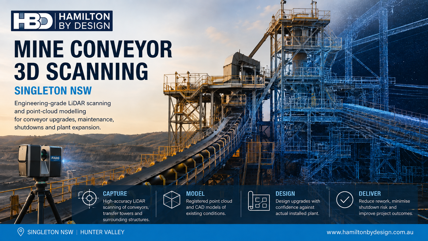


Mine Conveyor 3D Scanning Singleton NSW | Hamilton By Design

Mine conveyor 3D scanning in Singleton NSW using engineering-grade LiDAR, point-cloud modelling and CAD design

Mine Conveyor 3D Scanning Singleton NSW

Engineering-Grade LiDAR Scanning for Conveyor Upgrades, Maintenance and Plant Expansion

Mine conveyor systems are rarely static assets. Over their operating life, conveyors may be extended, shortened, re-aligned, reinforced or modified to suit changing production requirements. Transfer chutes are replaced, drives are upgraded, supporting structures are altered and access platforms are added around existing plant.

As these modifications accumulate, the physical conveyor system can progressively differ from the original engineering drawings.

This creates a practical problem for project and maintenance teams:

Conveyor upgrades can require repeated field measurements because available drawings do not always represent the installed condition accurately.

Hamilton By Design provides mine conveyor 3D scanning services in Singleton NSW and throughout the Hunter Valley, using engineering-grade terrestrial LiDAR scanning, registered point clouds and CAD modelling to capture existing conveyor systems and surrounding mine infrastructure.

The objective is to reduce repeated site measuring and provide engineers with a measurable digital representation of the actual installed plant before modification work begins.

For broader open-cut mining environments, Hamilton By Design also provides surface mine 3D LiDAR scanning across the Hunter Valley NSW, supporting existing-condition capture of mining, processing and materials-handling infrastructure.


The Problem: Repeated Field Measurements During Conveyor Upgrades

Brownfield conveyor projects frequently begin with incomplete information.

Existing drawings may show the original plant layout, but subsequent modifications may not have been fully incorporated into the available engineering documentation.

Typical discrepancies can include:

  • altered chute geometry;
  • modified structural steel;
  • replacement pulleys;
  • relocated equipment;
  • additional pipework and services;
  • changes to access platforms;
  • revised guarding;
  • undocumented shutdown modifications; and
  • differences between nominal and installed dimensions.

A project engineer may initially visit site to measure a conveyor upgrade area, return to the office and begin modelling, only to discover that another dimension is required.

This can produce an inefficient cycle:

Measure โ†’ design โ†’ identify missing information โ†’ return to site โ†’ remeasure โ†’ revise design.

Engineering-grade LiDAR scanning changes this process by capturing the wider plant environment rather than relying solely on isolated manual measurements.

The resulting registered point cloud allows additional measurements to be obtained digitally as the design develops.

A simple way to express the value is:

Capture once on site. Measure repeatedly from the point cloud.


What Mine Conveyor Infrastructure Can Be Scanned?

A conveyor scanning project can include much more than the belt itself.

Depending on the scope, terrestrial LiDAR can capture:

  • conveyor gantries;
  • stringers;
  • head pulleys;
  • tail pulleys;
  • take-up systems;
  • drive stations;
  • transfer towers;
  • chutes;
  • hoppers;
  • feeders;
  • idler arrangements;
  • structural steel;
  • walkways;
  • platforms;
  • stairs;
  • guards;
  • pipework;
  • cable trays;
  • concrete structures; and
  • adjacent equipment.

This wider capture is important because conveyor modification projects depend on the spatial relationship between multiple assets.

For example, a replacement chute must fit between the conveyor discharge point, receiving equipment, supporting steel and surrounding maintenance access.

The engineering problem is therefore not simply measuring one component.

It is understanding the complete installed environment around the component being modified.


Who Can Benefit from Mine Conveyor 3D Scanning?

Mine conveyor 3D scanning can assist:

  • mine owners and operators;
  • engineering managers;
  • project engineers;
  • mechanical engineers;
  • maintenance superintendents;
  • reliability teams;
  • shutdown planners;
  • CHPP engineers;
  • conveyor maintenance contractors;
  • EPCM organisations;
  • structural engineers;
  • fabricators; and
  • drafting teams.

For companies working across NSW coal operations, Hamilton By Design’s wider mining engineering and 3D scanning services in NSW can support projects beyond individual conveyor systems, including processing plant, structural and mechanical infrastructure.

The common requirement is reliable information about the existing plant before engineering decisions are made.


From Conveyor to Registered Point Cloud

1. Define the Engineering Requirement

Before scanning begins, the project team should establish the intended modification.

This may include:

  • chute replacement;
  • conveyor extension;
  • drive upgrade;
  • pulley replacement;
  • conveyor re-alignment;
  • transfer-station modification;
  • structural strengthening;
  • walkway modification; or
  • installation of new conveyor equipment.

Understanding the engineering requirement determines the scan coverage and level of detail required.


2. Capture the Existing Conveyor System

Terrestrial LiDAR scanners are positioned around the conveyor and surrounding infrastructure.

Each scan records a large number of three-dimensional spatial measurements.

Multiple scan positions allow equipment to be captured from different viewpoints and reduce areas hidden by surrounding structures.

This approach is particularly useful in complex brownfield environments where manual measurement would require numerous individual dimensions.


3. Register the Scan Data

Individual scans are processed and combined into a coordinated point-cloud dataset.

The resulting point cloud becomes a measurable record of the plant condition at the time of scanning.

Engineering personnel can then interrogate the dataset away from site and obtain additional dimensions as required.

This is particularly valuable where physical access is limited or where repeated measuring trips would interrupt engineering progress.


From Point Cloud to Engineering CAD

The point cloud may be sufficient for some projects, but other conveyor upgrades require selected infrastructure to be converted into CAD geometry.

Hamilton By Design provides surface mine Scan-to-CAD services throughout the Hunter Valley NSW to convert captured existing conditions into practical engineering models for brownfield design and plant modification.

Depending on the project, CAD geometry may include:

  • conveyor centreline;
  • pulley centres;
  • belt path;
  • structural steel;
  • chute geometry;
  • equipment interfaces;
  • support frames;
  • floor levels;
  • access structures; and
  • surrounding plant envelopes.

The objective is not to model every visible component unnecessarily.

Instead, the digital model should contain the information required to solve the engineering problem.


Designing Conveyor Upgrades Against Existing Conditions

Once the conveyor environment has been captured, proposed equipment can be developed directly against the existing point-cloud or CAD geometry.

This can support:

  • clearance assessment;
  • clash detection;
  • structural interfaces;
  • installation planning;
  • equipment positioning;
  • maintenance access;
  • conveyor alignment;
  • chute fit-up;
  • fabrication interfaces; and
  • shutdown preparation.

This allows potential problems to be identified before fabrication.

A strong engineering objective is therefore:

Find the interference digitally before finding it during installation.

This becomes increasingly important during mine shutdowns where installation windows may be short and delays can affect plant availability.


Conveyor and CHPP Projects in Singleton NSW

Singleton is located within one of Australia’s most significant coal-mining regions, with extensive materials-handling and coal-processing infrastructure throughout the surrounding Hunter Valley.

Conveyors form critical connections between mining, ROM handling, crushing, stockpiling and coal preparation systems.

Hamilton By Design’s CHPP 3D scanning services in Singleton NSW provide a closely related application where conveyor systems, transfer stations, chutes, structural steel and surrounding processing infrastructure can be captured to support shutdowns and brownfield modifications.

This makes conveyor scanning particularly relevant for:

  • CHPP upgrades;
  • transfer-station modifications;
  • new chute installations;
  • conveyor extensions;
  • structural changes;
  • equipment replacement; and
  • plant-expansion projects.

Reverse Engineering Existing Conveyor and Mining Equipment

Mining operations can also contain equipment for which reliable manufacturing information is no longer available.

Components may have been modified during previous shutdowns, suppliers may no longer support older equipment, or drawings may not reflect current configurations.

In these cases, reality capture can provide the starting geometry for reverse engineering.

Hamilton By Design’s open-cut mine machinery reverse-engineering services in Muswellbrook NSW demonstrate how LiDAR and engineering modelling can support legacy mining equipment and replacement-component development.

For conveyor projects, this approach may be useful for:

  • guards;
  • frames;
  • supports;
  • chute components;
  • equipment interfaces;
  • access structures; and
  • other existing mechanical assemblies.

The objective is not necessarily to copy an existing component exactly. Captured geometry can also provide the basis for a modified or improved replacement.


Practical Tools for Conveyor 3D Scanning

A mine conveyor 3D scanning project may involve several complementary technologies.

FARO Focus S70

Terrestrial LiDAR scanning can provide dense spatial capture of conveyor systems, transfer stations and surrounding infrastructure.

FARO Orbis

Mobile scanning may provide supplementary capture where rapid coverage is beneficial and appropriate to the engineering requirement.

FARO SCENE

Scan data can be processed and registered into coordinated point-cloud datasets.

Autodesk ReCap

Point clouds can be prepared for use within CAD and engineering software.

SolidWorks

Mechanical components, chute systems, equipment and fabrication models can be developed from captured geometry.

Autodesk Inventor and AutoCAD

These tools can support plant modelling, layouts, engineering drawings and mechanical design.

Navisworks

Large point clouds and proposed design models can be reviewed together for coordination and clash checking.

Rocky DEM

Where a project involves chute or transfer-point performance, discrete element modelling can assist with analysing material flow, trajectories, wear zones and impact behaviour.

Rocky DEM is not required for every conveyor project, but it can become valuable when the engineering problem extends beyond dimensional fit-up into bulk-material behaviour.


Typical Deliverables

Depending on the scope, mine conveyor scanning deliverables may include:

  • registered E57 point clouds;
  • RCP and RCS datasets;
  • LAS files;
  • measurable point-cloud datasets;
  • existing-condition CAD models;
  • SolidWorks models;
  • STEP files;
  • Parasolid files;
  • DWG and DXF drawings;
  • general arrangement drawings;
  • sections and elevations;
  • existing-versus-proposed models;
  • clash-review models;
  • eDrawings; and
  • PDF engineering documentation.

Some projects may require only a registered point cloud.

Others may extend through:

Scan โ†’ Register โ†’ Model โ†’ Engineer โ†’ Draw โ†’ Fabricate.


Mine Conveyor 3D Scanning Singleton NSW

For conveyor upgrades, one of the greatest sources of engineering uncertainty is incomplete knowledge of the existing plant.

Repeated site visits may provide additional dimensions, but they can also interrupt design progress, increase travel requirements and still leave important spatial relationships undocumented.

Engineering-grade terrestrial LiDAR provides an alternative approach.

By capturing the conveyor and surrounding infrastructure as a registered point cloud, project teams can obtain a reusable digital record of the installed condition.

This information can then support CAD modelling, brownfield engineering, fabrication planning, shutdown preparation and future plant modifications.

For mine operators and contractors working throughout Singleton and the Hunter Valley NSW, the principle is straightforward:

Capture the conveyor once. Measure digitally as the engineering develops. Design against what is actually installed.


Hamilton By Design logo displayed on a blue tilted rectangle with a grey gradient background

Contact Us – Talk To Us

Name
Would you like us to arrange a phone consultation for you?
Address

Our clients:
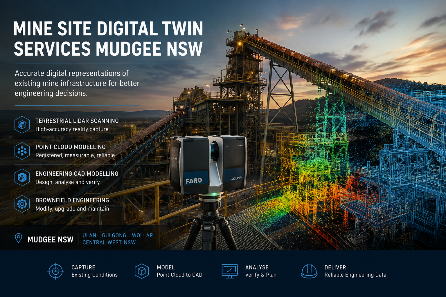


Mine Site Digital Twin Services Mudgee NSW | Hamilton By Design

Mine site digital twin services in Mudgee NSW using terrestrial LiDAR scanning, point cloud modelling and engineering CAD

Mine Site Digital Twin Services Mudgee NSW

Engineering Digital Twins Using Terrestrial LiDAR, Point Clouds and CAD Modelling

Mining infrastructure rarely remains exactly as it was originally designed. Over the operational life of a mine, equipment is replaced, conveyors are modified, pipework is rerouted, structures are strengthened, access systems are altered and processing equipment is progressively upgraded.

As these changes accumulate, the physical configuration of a mine or processing facility can diverge significantly from the drawings, models and other engineering records available to project and maintenance teams.

Hamilton By Design provides mine site digital twin services for Mudgee, Ulan, Gulgong, Wollar and the wider Central West NSW region, using terrestrial LiDAR scanning, point-cloud processing and engineering CAD workflows to establish reliable digital representations of existing mine infrastructure.

The objective is not simply to produce a visually impressive 3D model. It is to establish an accurate and measurable engineering record that can support brownfield modifications, shutdown planning, maintenance, equipment replacement, design verification and future asset development.

Put simply:

Capture the existing condition accurately, establish a reliable digital baseline and design around what is actually installed.


The Engineering Problem: When Existing Drawings No Longer Represent the Site

Mining and mineral-processing assets may remain operational for several decades. During this period, individual areas of plant can undergo numerous modifications.

A pipe may be rerouted during a shutdown. A transfer chute may be replaced. Structural steel may be strengthened to accommodate changing loads. Conveyor drives and pulleys may be modified. New cable trays, services, platforms or equipment may be installed around existing infrastructure.

Although engineering change-management systems aim to record these modifications, older facilities can contain areas where available documentation does not fully correspond with the current installed condition.

This creates uncertainty during subsequent engineering projects.

A project team may therefore have drawings showing what was originally designed but insufficient information about what exists today.

Hamilton By Design’s engineering-grade 3D laser scanning for mining and industrial projects addresses this problem by capturing the existing physical environment before detailed engineering decisions are made.

The resulting spatial information can reduce reliance on assumptions and provide engineers with a measurable basis for subsequent design development.


What Is a Mine Site Engineering Digital Twin?

The term digital twin is applied to a broad range of technologies.

At a sophisticated level, a digital twin may integrate physical geometry with operational sensors, process information, maintenance records and real-time asset data.

However, an effective digital-twin strategy does not necessarily need to begin with this level of complexity.

For brownfield mine engineering, one of the most useful foundations is an engineering or geometric digital twin: a reliable digital representation of the existing physical asset.

It may include:

  • conveyors and transfer stations;
  • chutes and hoppers;
  • crushers and screening equipment;
  • structural steel;
  • platforms, stairs and access systems;
  • pumps and mechanical equipment;
  • tanks and vessels;
  • pipework and services;
  • processing plant;
  • buildings and plant rooms; and
  • interfaces between existing and proposed equipment.

A point cloud may provide the underlying evidence of the existing condition, while selected infrastructure is converted into CAD or BIM geometry according to the purpose of the engineering project.

Hamilton By Design’s Scan to BIM services for mining and industrial facilities provide a complementary workflow where captured site information needs to be transformed into structured digital models.


Who Benefits from a Mine Site Digital Twin?

Mine site digital twins can support a broad range of technical and operational stakeholders, including:

  • mine owners and operators;
  • engineering managers;
  • project engineers;
  • mechanical and structural engineers;
  • maintenance and reliability teams;
  • asset managers;
  • shutdown planners;
  • EPCM organisations;
  • fabrication contractors; and
  • drafting and design teams.

The central question is not simply who requires a 3D model.

The more useful question is:

Who needs reliable information about the existing plant to make an engineering decision?

For example, a project engineer modifying a conveyor transfer station may require accurate structural interfaces. A maintenance engineer replacing a pump may need to understand the existing pipework arrangement and mounting geometry. A shutdown planner may need assurance that replacement equipment can physically move through existing access routes and fit within the available space.

Each stakeholder can make different use of the same underlying digital asset.


From Physical Mine Site to Engineering Digital Twin

A practical digital-twin workflow can be divided into several stages.

1. Define the Engineering Requirement

The first stage is to understand how the captured information will ultimately be used.

Questions may include:

  • What infrastructure is being modified?
  • Which interfaces are important?
  • What level of dimensional accuracy is required?
  • Is the objective conceptual engineering, detailed design or fabrication?
  • Does the client require point-cloud information, CAD geometry, drawings or a combination of deliverables?

Defining the engineering purpose helps avoid creating unnecessary information while ensuring critical interfaces are captured.


2. Capture Existing Conditions Using Terrestrial LiDAR

Terrestrial LiDAR scanning captures large quantities of three-dimensional spatial information from positions throughout an industrial environment.

Multiple scanner locations are subsequently combined to represent complex plant areas containing equipment, steelwork, pipework, conveyors and other infrastructure.

For operating mine sites, this approach can provide considerably more spatial information than isolated manual measurements while reducing the need for engineering personnel to repeatedly access difficult or congested areas.

The same methodology is particularly relevant to coal processing facilities. Hamilton By Design’s work relating to 3D scanning for CHPP and coal wash plant shutdowns demonstrates how accurate existing-condition data can support projects where shutdown duration and installation uncertainty are significant considerations.


3. Register and Process the Point Cloud

Individual scans are processed and registered into a coordinated point-cloud dataset.

The registered dataset creates a measurable representation of the environment captured during the survey.

Depending on project requirements, point-cloud deliverables may include formats such as E57, RCP, RCS or LAS.

The point cloud can then become a reference against which existing drawings, proposed equipment and engineering models are compared.

Importantly, the point cloud should not be viewed as the engineering conclusion.

It is the evidence from which engineering decisions can be developed.


Converting Captured Data into Engineering Geometry

For many projects, the next stage is to reconstruct selected infrastructure as engineering CAD geometry.

Not every item visible within a point cloud needs to be modelled.

Instead, an effective digital-twin strategy applies an appropriate level of information to the engineering requirement.

For example, a conveyor modification may require accurate models of the conveyor centreline, pulley positions, supporting steel and adjacent equipment while surrounding infrastructure is retained as point-cloud context.

Hamilton By Design’s 3D CAD modelling services in Australia support this transition from site information into practical engineering geometry suitable for design development, interference checking, drawings and fabrication planning.

This distinction is important because a digital twin should be developed for an engineering purpose rather than simply to maximise model complexity.


Digital Twins for Brownfield Mine Modifications

The value of accurate digital information becomes particularly apparent in brownfield environments.

Unlike greenfield projects, brownfield engineering must integrate new equipment with existing infrastructure, often within restricted spaces and limited shutdown periods.

Common constraints include:

  • legacy drawings;
  • undocumented modifications;
  • restricted physical access;
  • congested pipework and services;
  • existing structural interfaces;
  • limited installation tolerances; and
  • short shutdown windows.

Hamilton By Design’s approach to brownfield industrial upgrades combines reality capture with scan-to-CAD and mechanical engineering to reduce uncertainty before fabrication and installation.

A digital twin can therefore become more than an as-built record. It can provide the spatial framework within which proposed modifications are assessed.


Supporting Mechanical Engineering and Plant Modification

The benefits of digital capture become more significant when the resulting information is integrated directly into engineering.

Hamilton By Design provides mining engineering services for Australian operations that combine existing-condition capture with mechanical design, structural considerations, CAD modelling and fabrication-oriented documentation.

Potential applications include:

  • conveyor modifications;
  • transfer-station upgrades;
  • equipment replacement;
  • new access platforms;
  • pipework alterations;
  • pump and equipment installations;
  • structural modifications;
  • shutdown projects; and
  • plant life-extension works.

In this context, LiDAR determines where the existing assets are, while engineering determines what should change and how the proposed modification can be safely manufactured, installed and maintained.


Digital Twins for Conveyors, Chutes and Materials Handling

Bulk-material-handling infrastructure is particularly suited to digital-twin workflows because conveyor systems, transfer points, chutes, hoppers and structural supports operate as interconnected systems.

Small changes to one component can affect surrounding equipment.

For example, changing chute geometry may influence material trajectory, supporting steel, conveyor loading, maintenance access and surrounding services.

Hamilton By Design’s work in bulk material handling engineering for mining operations demonstrates the importance of considering the relationship between ROM facilities, conveyors, transfer stations, chutes and associated infrastructure.

Accurate digital capture provides an important starting point because engineering modifications can be developed against the actual arrangement rather than an assumed one.


Reverse Engineering Existing Mine Assets

Mine sites frequently contain equipment for which reliable manufacturing information is unavailable.

Original suppliers may no longer exist, documentation may have been lost, or an asset may have undergone multiple modifications during its operating life.

Digital capture can provide the starting geometry for reverse engineering.

Hamilton By Design’s reverse-engineering 3D scanning services combine measured geometry with engineering interpretation to support replacement components, legacy equipment, equipment interfaces and fabrication documentation.

The objective is not always to reproduce an existing component exactly.

In some cases, the captured geometry provides the baseline from which an improved or modified replacement can be engineered.


Mine Site Digital Twin Services for Mudgee and Central West NSW

Mudgee is strategically located within an established mining region encompassing major operations and supporting infrastructure around Ulan, Gulgong, Wollar and the wider Central West NSW area.

These operating environments contain substantial materials-handling, processing, structural and mechanical infrastructure that has developed progressively over time.

For mine operators and engineering contractors, maintaining reliable knowledge of existing conditions can support better decision-making during future projects.

Digital-twin workflows can be particularly valuable where projects involve:

  • ageing infrastructure;
  • repeated plant modifications;
  • incomplete or inconsistent drawings;
  • geographically dispersed engineering teams;
  • difficult-to-access plant areas;
  • short shutdown periods; and
  • complex new-to-existing interfaces.

Once captured, engineering teams can interrogate the digital environment away from site, potentially reducing repeated site visits for routine dimensional verification.


Technology Supporting the Digital-Twin Workflow

Depending on project requirements, Hamilton By Design can combine several technologies.

FARO Focus terrestrial LiDAR scanning can provide detailed spatial capture of mine and industrial infrastructure.

FARO SCENE supports registration and processing of scan data.

Autodesk ReCap provides point-cloud preparation and interoperability with engineering applications.

SolidWorks supports mechanical design, equipment development and reverse-engineering workflows.

Autodesk Inventor and AutoCAD provide additional mechanical modelling and drafting capability.

Navisworks can assist with coordination, model review and larger digital datasets.

Potential client deliverables may include E57, RCP, RCS and LAS point clouds together with SolidWorks files, STEP, SAT, Parasolid, DWG, DXF, eDrawings and PDF engineering documentation.

The technology itself, however, should not be regarded as the final product.

The principal deliverable is reliable engineering information that assists decision-making.


Developing the Digital Twin Progressively

A mine does not necessarily need to create a complete digital representation of every asset during a single project.

For many operating facilities, a progressive strategy may provide greater value.

One conveyor transfer station could be scanned during an initial modification. A processing area could subsequently be captured for another project. Pipework, structural systems and other critical assets could then be incorporated as operational requirements arise.

Future LiDAR surveys can also update areas that have changed.

Over time, individual project datasets can contribute towards a more comprehensive digital engineering record of the facility.

This approach connects expenditure directly with engineering requirements while progressively increasing the quality of available asset information.


Frequently Asked Questions

What is a mine site digital twin?

A mine site digital twin is a digital representation of physical mining infrastructure. For engineering applications, it may combine registered LiDAR point clouds with CAD or BIM geometry to provide measurable information about existing assets and their spatial relationships.

Is a point cloud the same as a digital twin?

Not necessarily. A point cloud records the measured geometry of a physical environment and can provide the foundation for a digital twin. Additional CAD, BIM, engineering or asset information may then be incorporated according to the required application.

Why use LiDAR when existing mine drawings are available?

Existing drawings remain important engineering records. However, on older or progressively modified facilities they may not completely represent current conditions. LiDAR provides independent evidence of the physical configuration present at the time of scanning.

Does the entire mine site need to be modelled?

No. A fit-for-purpose approach generally focuses on the assets and interfaces required for the immediate engineering problem. Additional infrastructure can be captured and modelled progressively.

Can digital twins help with mine shutdowns?

Yes. Existing-condition information can support engineering, interference assessment, equipment fit checks and installation planning before a shutdown begins, reducing the amount of dimensional uncertainty that needs to be resolved during the shutdown period.

What mine infrastructure can be captured?

Potential applications include conveyors, transfer stations, chutes, hoppers, structural steel, platforms, pipework, pumps, tanks, processing equipment, buildings and surrounding infrastructure.

Can point-cloud information be used remotely?

Yes. Once captured and appropriately processed, digital site information can support engineering and project teams operating away from the physical mine site, subject to the client’s data-management and software requirements.

What file formats can be supplied?

Depending on scope and client requirements, deliverables may include registered point clouds in formats such as E57, RCP, RCS and LAS, together with CAD models and engineering information in formats including STEP, SAT, Parasolid, DWG, DXF, eDrawings and PDF.

Do you provide mine site digital twin services around Mudgee?

Hamilton By Design can support mine and industrial projects throughout Mudgee, Ulan, Gulgong, Wollar and Central West NSW, providing engineering-led terrestrial LiDAR scanning, point-cloud processing, CAD modelling and associated mechanical engineering support.


Engineering Digital Twins for Mudgee Mine Infrastructure

Where existing drawings no longer provide sufficient certainty for brownfield engineering, an accurate digital representation of the installed asset can provide a more reliable foundation for decision-making.

Hamilton By Design combines terrestrial LiDAR scanning, point-cloud processing, 3D CAD modelling and practical mechanical engineering to transform existing mine infrastructure into usable digital engineering information.

The objective is not to create a digital model for its own sake.

It is to improve the quality of information available to engineers, maintenance teams and project managers before critical decisions are made.

Capture the existing condition. Establish the digital baseline. Reduce uncertainty. Engineer around what is actually there.


Hamilton By Design logo displayed on a blue tilted rectangle with a grey gradient background

Contact Us – Talk To Us

Name
Would you like us to arrange a phone consultation for you?
Address

Our clients:


,

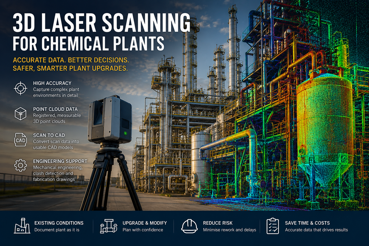
3D Laser Scanning for Chemical Plants | Hamilton By Design

3D laser scanning for chemical plants with Hamilton By Design logo, showing an engineer using a laser scanner in front of a process plant with point cloud and CAD model overlay.

3D Laser Scanning for Chemical Plants

Chemical plants are often complex, congested and difficult to measure accurately. Existing drawings may be incomplete, outdated or no longer reflect modifications made during previous maintenance and upgrade projects.

Hamilton By Design provides engineering-led 3D laser scanning, point-cloud processing, CAD modelling and mechanical engineering support for chemical plants and process facilities across Australia.

Our service helps plant owners, engineering teams, maintenance departments and contractors capture accurate existing-condition information before equipment replacement, pipework modifications, structural upgrades or brownfield construction work begins.

The Goal

The goal of 3D laser scanning is to create an accurate and measurable digital record of the existing chemical plant.

This information can then be used to:

  • Plan plant upgrades and modifications
  • Verify existing dimensions
  • Develop accurate CAD models and drawings
  • Coordinate new equipment with existing infrastructure
  • Identify potential clashes
  • Reduce site measurement uncertainty
  • Support fabrication and installation planning
  • Improve shutdown preparation
  • Document existing plant conditions
  • Reduce rework and installation delays

Rather than designing from outdated drawings or site assumptions, project teams can work from captured plant geometry.

The Problem

Chemical plants can contain extensive networks of pipework, tanks, vessels, pumps, valves, structural steel, platforms, electrical services and process equipment.

These environments can be difficult to measure using traditional manual methods.

Common challenges include:

  • Congested pipework and services
  • Restricted access around equipment
  • Limited shutdown or inspection windows
  • Outdated or incomplete drawings
  • Plant modifications that have not been documented
  • Equipment positioned at different elevations
  • Difficult-to-reach structural connections
  • Tight fabrication and installation tolerances
  • Safety restrictions around operating plant
  • Limited visibility behind equipment and services

When engineering work is based on incomplete or inaccurate information, the result may include pipe spools that do not fit, equipment installation clashes, incorrect support locations, additional site welding, extended shutdowns and costly fabrication rework.

The Solution

Hamilton By Design uses terrestrial 3D laser scanning to capture the visible geometry of the existing chemical plant.

Multiple scans are taken from carefully selected positions and registered together to create a measurable three-dimensional point cloud.

The point cloud can then be used to develop practical engineering deliverables, including:

  • Registered point-cloud datasets
  • Existing-condition plant models
  • Scan-to-CAD models
  • SolidWorks models
  • Equipment and pipework layouts
  • General arrangement drawings
  • Sections and elevations
  • Fabrication drawings
  • Structural steel models
  • Clearance and access studies
  • Clash-detection models
  • Proposed plant modification models

This process gives engineers and designers a more reliable foundation for planning upgrades around actual site conditions.

Services Provided by Hamilton By Design

Hamilton By Design can provide a combination of onsite scanning, data processing, CAD modelling, drafting and mechanical engineering services.

Depending on the project requirements, the service may include:

3D Laser Scanning

Onsite capture of chemical plant areas using terrestrial LiDAR scanning equipment.

Point-Cloud Registration

Processing and registering individual scan positions into a coordinated and measurable point-cloud dataset.

Existing-Condition Documentation

Creation of an accurate digital record of existing equipment, pipework, structural steel, platforms and surrounding infrastructure.

Scan-to-CAD Modelling

Conversion of selected point-cloud information into usable 2D drawings or 3D CAD models.

SolidWorks Modelling

Development of SolidWorks parts, assemblies and plant models for engineering review, equipment coordination and modification planning.

Mechanical Engineering Support

Engineering input for equipment upgrades, maintenance projects, plant modifications and brownfield design work.

Fabrication Drawings

Preparation of drawings for structural steel, platforms, supports, equipment frames, pipe supports and other plant components.

Clash and Clearance Reviews

Assessment of proposed equipment, structures or pipework against the captured existing plant environment.

Shutdown Planning Support

Capture of existing conditions before a shutdown to help reduce uncertainty during fabrication and installation.

Typical Chemical Plant Areas That Can Be Scanned

3D laser scanning may be suitable for capturing:

  • Process pipework
  • Tanks and vessels
  • Pumps and pump bases
  • Valves and manifolds
  • Pipe racks
  • Structural steel
  • Platforms and access ways
  • Stairs and handrails
  • Equipment foundations
  • Skids and packaged equipment
  • Ducting and ventilation systems
  • Conveyors and material-handling equipment
  • Maintenance access areas
  • Plant rooms
  • External processing areas
  • Existing equipment interfaces

The final scanning scope should be based on the project objectives, access conditions and required engineering deliverables.

Common Applications

3D laser scanning can support a range of chemical plant projects, including:

  • Brownfield plant upgrades
  • Equipment replacement
  • Pipework modifications
  • New equipment installation
  • Plant-layout verification
  • Structural modifications
  • Platform and access upgrades
  • Pump and skid replacement
  • Shutdown preparation
  • Fabrication planning
  • Existing-condition surveys
  • Reverse engineering
  • As-built documentation
  • Clash detection
  • Maintenance planning
  • Asset documentation

Available Deliverables

Deliverables can be tailored to suit the clientโ€™s preferred software and intended use.

Typical file formats may include:

  • E57 point-cloud files
  • RCP and RCS files
  • LAS files
  • Registered scan project files
  • SolidWorks part and assembly files
  • STEP files
  • SAT files
  • Parasolid files
  • DWG and DXF drawings
  • Measurable eDrawings
  • General arrangement drawings
  • PDF drawings
  • Sections and elevations
  • Fabrication drawings

Before processing begins, it is important to confirm how the client intends to open, measure, review or modify the delivered files.

Important Scanning Limitations

A laser scanner captures visible surfaces from the scannerโ€™s line of sight.

It does not automatically capture:

  • Buried services
  • Internal pipe conditions
  • Equipment hidden behind cladding
  • Internal vessel geometry without access
  • Surfaces blocked by equipment or structures
  • Areas obscured by steam, dust or process emissions
  • Material specifications
  • Wall thicknesses
  • Internal corrosion
  • Process operating information

Multiple scanning positions can reduce hidden areas, but some locations may still require manual measurement, existing drawings or additional inspection methods.

Safety and Site Access

Chemical plants may contain hazardous substances, operating machinery, pressurised equipment, hot surfaces and restricted work areas.

Scanning activities must therefore be planned around the facilityโ€™s existing safety requirements.

Project planning may include:

  • Site inductions
  • Permit requirements
  • Hazardous-area restrictions
  • Exclusion zones
  • Personal protective equipment
  • Plant operating conditions
  • Access limitations
  • Working-at-height requirements
  • Confined-space restrictions
  • Coordination with plant personnel
  • Shutdown or isolation requirements

The scanning methodology should be developed in consultation with the clientโ€™s site and safety representatives.

Why Hamilton By Design?

Hamilton By Design combines 3D laser scanning with mechanical engineering, CAD modelling, drafting and practical plant experience.

This means the service is focused on creating useful engineering information rather than simply supplying raw scan data.

Clients can engage Hamilton By Design for the full workflow, including:

  1. Project scoping
  2. Onsite scanning
  3. Point-cloud registration
  4. Existing-condition review
  5. CAD modelling
  6. Engineering development
  7. Drawing preparation
  8. Fabrication and installation support

This integrated approach can help reduce the number of handovers between scanning, drafting, engineering and fabrication providers.

Frequently Asked Questions

What is 3D laser scanning for a chemical plant?

3D laser scanning is a non-contact measurement process that records millions of points from visible plant surfaces. These points form a three-dimensional point cloud representing the existing chemical plant environment.

Why use 3D laser scanning instead of manual measurements?

Manual measurements can be difficult in congested chemical plants. Laser scanning captures a much larger amount of spatial information and helps document the relationships between pipework, equipment, structures and access areas.

Can the scan data be measured?

Yes. A registered point cloud can be opened in compatible software and used to take measurements. The accuracy and suitability of those measurements depend on the scanning method, registration quality, site conditions and required project tolerance.

What accuracy can be expected?

Accuracy depends on the scanner, scan distance, plant conditions, registration method and project requirements. The required accuracy should be discussed before the scanning scope is finalised.

Can you create a SolidWorks model from the scans?

Yes. Selected equipment, structures, pipework and plant geometry can be modelled in SolidWorks using the registered point cloud as a reference.

The level of model detail should be agreed before work begins.

Can you model an entire chemical plant?

Potentially, but complete plant modelling can involve a significant amount of work. It is often more efficient to model only the areas and equipment required for the proposed project.

Can 3D scanning identify internal pipe corrosion?

No. Terrestrial laser scanning captures visible external surfaces. It does not measure internal corrosion, wall thickness or internal pipe condition.

Other inspection methods would be required.

Can scanning be completed while the plant is operating?

In some cases, yes. This depends on site access, safety requirements, hazardous areas, moving equipment, temperature, emissions and operational restrictions.

The client must determine whether the area is safe and accessible for scanning.

Does the scanner need to touch the equipment?

No. Terrestrial laser scanning is generally a non-contact measurement method.

Can scanning reduce shutdown time?

Scanning can improve shutdown preparation by allowing more design, coordination and fabrication work to be completed before site installation begins.

It cannot guarantee that delays or rework will be eliminated, but it can reduce uncertainty associated with existing plant conditions.

What information is required before scanning?

Useful project information includes:

  • The plant location
  • The areas to be scanned
  • The purpose of the scan
  • Required deliverables
  • Preferred file formats
  • Required accuracy
  • Available access windows
  • Site safety requirements
  • Existing drawings
  • The software the client intends to use

What software can be used to open the files?

This depends on the selected deliverables. Point-cloud and CAD files may be prepared for software such as Autodesk ReCap, AutoCAD, Navisworks, SolidWorks or other compatible engineering platforms.

Do you provide raw scan data?

Raw or registered scan data can be included if it is specified in the agreed project scope.

The client should confirm whether they require raw scans, registered point clouds, CAD models, drawings or a combination of deliverables.

Can the point cloud be used for clash detection?

Yes. A registered point cloud can be compared with proposed equipment, pipework or structural models to identify potential spatial conflicts.

Can you prepare fabrication drawings?

Yes. Hamilton By Design can use the scan data to support the preparation of fabrication drawings for selected plant components, structures, supports, platforms and equipment modifications.

Can you scan tanks and pressure vessels?

The external visible surfaces of tanks and vessels can generally be scanned where safe access and line of sight are available.

Internal scanning would require safe internal access, appropriate isolation and separate site approval.

Can you scan pipe racks and structural steel?

Yes. Pipe racks, structural steel, platforms, stairs and access systems can be captured where they are visible from suitable scanner positions.

Will the scan show every pipe and connection?

Not necessarily. Congested plant areas can create shadows where one object blocks another. Multiple scanning positions can reduce these hidden areas, but some concealed geometry may remain.

Do you provide engineering certification?

Engineering certification is separate from the scanning process. Any certification requirement must be clearly defined and assessed as part of the engineering scope.

How long does scanning take?

The duration depends on the size and complexity of the plant, site access, safety requirements, required coverage and number of scan positions.

A small plant area may be captured within a day, while a larger or more complex facility may require several days.

How long does point-cloud processing take?

Processing time depends on the number of scans, project size, registration complexity and required deliverables.

Point-cloud registration and CAD modelling should be treated as separate project stages.

What is the best first step?

The best first step is to define the area to be scanned, the reason for the scan and the required final deliverables.

It is also helpful to confirm what software the project team intends to use to open and review the files.

Request a Chemical Plant Scanning Assessment

Hamilton By Design can assist with 3D laser scanning, point-cloud registration, CAD modelling, mechanical engineering and drafting for chemical plant upgrades and existing-condition documentation.

To discuss a project, provide:

  • The chemical plant location
  • The approximate area to be scanned
  • The proposed project or modification
  • Available site access dates
  • Required file formats
  • Preferred engineering software
  • Existing drawings or photographs
  • Required accuracy or tolerances
  • Expected final deliverables

Hamilton By Design can then help develop an appropriate scanning and engineering scope for the project.


Hamilton By Design logo displayed on a blue tilted rectangle with a grey gradient background

Contact Us – Talk To Us

Name
Would you like us to arrange a phone consultation for you?
Address

Our clients:


Related 3D Laser Scanning & Engineering Services

Explore additional Hamilton By Design services for industrial plants, brownfield upgrades, point cloud modelling and mechanical engineering.

3D Laser Scanning Australia

Engineering-grade 3D laser scanning and LiDAR reality capture for industrial plants, infrastructure, mining and brownfield projects.

Engineering-Grade LiDAR Scanning

High-accuracy LiDAR scanning for industrial and mining assets where reliable existing-condition data is required for engineering decisions.

3D Laser Scanning for Engineering

Engineer-led scanning for plant upgrades, shutdown planning, fit-up verification, clash checking and fabrication-ready design.

3D Scanning for Mining & Industrial Projects

Engineering-grade point cloud capture and modelling for complex processing plants, industrial facilities and heavy infrastructure.

Point Cloud to AutoCAD

Convert registered laser scan data into practical AutoCAD layouts, plant models, sections and engineering drawings.

Point Cloud to Engineering Model Workflow

See how laser scan data progresses from site capture and registration through to usable CAD models and engineering documentation.

SolidWorks Point Cloud to CAD Workflow

Transform LiDAR point clouds into detailed SolidWorks engineering models, assemblies and fabrication documentation.

SolidWorks 3D Modelling Services

Detailed mechanical, structural, piping and equipment modelling developed from LiDAR scans, drawings and measured site information.

Mechanical Engineering Services

Mechanical design, plant modifications, equipment layouts, verification and engineering support for industrial facilities.

Engineering Services

Integrated LiDAR scanning, CAD modelling, mechanical engineering, drafting and verification for industrial and infrastructure projects.

Brownfield Industrial Upgrades

Reality capture and engineering design for existing plants where outdated drawings, restricted access and shutdown constraints increase risk.

LiDAR Scanning for Industrial Retrofit Engineering

Existing-condition capture for plant modifications, equipment replacement, retrofit projects and brownfield facility upgrades.

Reverse Engineering with 3D Scanning

Capture existing components and equipment to develop accurate replacement models, drawings and fabrication-ready information.

Scan-to-CAD for Reverse Engineering

Learn how physical plant and components can be converted into engineering CAD models and fabrication drawings.

Why 3D Scanning Accuracy Matters

Understand why scan coverage, point density and engineering context matter when point clouds are being used for design and fabrication.

Scan to BIM Australia

Convert accurate reality-capture data into structured digital models for existing buildings, industrial plants and infrastructure.

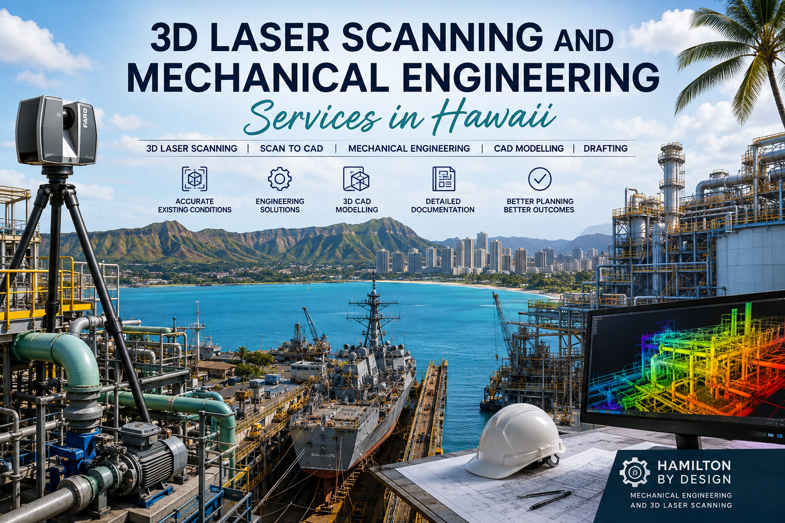
3D Laser Scanning and Mechanical Engineering Services Hawaii

3D laser scanning and mechanical engineering services in Hawaii showing a LiDAR scanner, industrial plant, shipyard, CAD point-cloud model and Honolulu coastline.

3D Laser Scanning and Mechanical Engineering Services in Hawaii

Hamilton By Design provides engineer-led 3D laser scanning, LiDAR reality capture, mechanical engineering, 3D CAD modelling and drafting support for industrial, marine, infrastructure and commercial projects in Hawaii.

Our integrated approach connects accurate existing-condition capture with practical engineering development.

Rather than providing a point cloud as an isolated deliverable, we can use captured site information to support equipment modifications, brownfield upgrades, mechanical layouts, reverse engineering, clash reviews, installation planning and fabrication documentation.

Services can be scoped for projects across Oสปahu, Maui, Hawaiสปi Island, Kauaสปi and other accessible locations throughout the Hawaiian Islands.

Engineering-Grade 3D Laser Scanning in Hawaii

Existing drawings are not always sufficiently accurate for plant modifications, equipment replacement or retrofit projects.

Buildings, machinery, services and structures may have been altered without the original drawings being updated. This creates uncertainty during design and increases the risk of clashes, fabrication changes and installation delays.

Hamilton By Design uses terrestrial LiDAR scanning to capture measurable existing conditions.

A registered point cloud can document visible features such as:

  • industrial machinery
  • marine equipment
  • structural steel
  • pipework
  • tanks and vessels
  • conveyors
  • platforms and stairs
  • plant rooms
  • building interiors
  • overhead services
  • ports and waterfront infrastructure
  • manufacturing equipment
  • utilities and service corridors

The captured information can provide an accurate spatial reference for engineering, modelling, planning and documentation.

Learn more about our engineering-grade 3D laser scanning services.

Mechanical Engineering Support for Existing Facilities

Mechanical engineering projects in operating facilities often involve working around existing machinery, structures, services and access restrictions.

Hamilton By Design can use measured site information to support:

  • equipment replacement
  • machinery relocation
  • plant modifications
  • mechanical layouts
  • maintenance-access improvements
  • conveyor and chute upgrades
  • pump and pipework arrangements
  • tank and vessel modifications
  • access-platform development
  • machine guarding
  • reverse engineering
  • fabrication planning
  • shutdown preparation
  • installation sequencing

The engineering scope can be developed incrementally, beginning with site capture and progressing through modelling, concept development and detailed documentation.

Explore our broader mechanical and digital engineering services.

Scan-to-CAD Modelling

A point cloud provides a detailed record of the visible environment, but it may not be the final deliverable required by the project team.

Hamilton By Design can convert selected point-cloud information into practical CAD geometry.

Depending on the project, Scan-to-CAD outputs may include:

  • existing-condition 3D models
  • machinery envelopes
  • structural reference models
  • equipment arrangements
  • general arrangement drawings
  • floor plans
  • elevations and sections
  • pipe and service routes
  • installation interfaces
  • fabrication reference geometry
  • clash-review models

It is not always necessary to model every object captured by the scanner.

The modelling scope can focus on the machinery, structures and services that directly influence the project. The remainder of the point cloud can stay available as a measurable spatial reference.

Learn more about 3D CAD modelling and mechanical drafting.

Industrial and Manufacturing Facilities

Hawaii contains food-production facilities, workshops, warehouses, processing operations, maintenance facilities and other industrial assets that may require accurate existing-condition documentation.

3D laser scanning and mechanical engineering can support:

  • factory layout changes
  • machinery installations
  • production-line modifications
  • packaging equipment upgrades
  • processing equipment replacement
  • equipment relocation
  • conveyor installation
  • utility coordination
  • access and clearance reviews
  • brownfield factory upgrades

Proposed machinery can be positioned within the scanned facility to assess fit, maintenance access and surrounding constraints before installation begins.

For projects involving factory and production equipment, see our Manufacturing Layout Design Australia service.

Marine and Ship-Repair Engineering

Marine environments often contain complex arrangements of machinery, structures, pipework, confined spaces and curved surfaces.

3D laser scanning may support marine and ship-repair projects involving:

  • vessel machinery spaces
  • engine rooms
  • deck equipment
  • marine pipework
  • structural modifications
  • equipment replacement
  • retrofit projects
  • access platforms
  • lifting arrangements
  • shore-based marine facilities
  • shipyard workshops
  • dry-dock infrastructure

The registered point cloud can provide a measurable reference for developing equipment layouts, replacement components and installation documentation.

For marine projects, the scope should account for access restrictions, vessel movement, corrosion, confined spaces and the required project coordinate system.

Ports and Waterfront Infrastructure

Hawaiiโ€™s island geography places significant importance on ports, harbours and waterfront infrastructure.

Engineering-grade reality capture can support projects involving:

  • cargo-handling equipment
  • wharf structures
  • loading facilities
  • conveyors
  • access platforms
  • maintenance structures
  • pipework and services
  • warehouses
  • terminals
  • mechanical equipment
  • utility upgrades
  • equipment replacement

LiDAR scanning can document existing conditions before maintenance, refurbishment or equipment installation work begins.

The captured information may also support contractor coordination, fabrication planning, as-built documentation and future asset-management requirements.

Energy and Utility Infrastructure

Reliable energy, water and utility infrastructure is particularly important in island environments.

Hamilton By Design can support existing-condition capture and mechanical documentation for:

  • power-generation facilities
  • pump stations
  • water-treatment assets
  • wastewater facilities
  • pipework systems
  • tanks
  • plant rooms
  • mechanical equipment
  • utility corridors
  • renewable-energy infrastructure
  • backup-generation equipment
  • cooling and ventilation systems

3D scanning can be valuable where plant areas are congested or where existing drawings do not accurately represent the installed condition.

Food and Beverage Production

Food and beverage facilities can include tightly coordinated machinery, conveyors, packaging lines, tanks, pipework and washdown services.

Manufacturing-layout and scanning services may support:

  • production-line rearrangements
  • packaging equipment installations
  • conveyor modifications
  • tank and vessel replacement
  • pipework coordination
  • hygienic access planning
  • washdown-area documentation
  • drainage coordination
  • maintenance-clearance reviews
  • equipment-removal planning

Accurate site capture can help document facilities that have changed progressively through multiple production upgrades.

Hotels, Resorts and Commercial Facilities

Hawaiiโ€™s commercial and hospitality facilities may also require accurate existing-condition information for refurbishment and upgrade projects.

Potential applications include:

  • plant-room documentation
  • mechanical-services coordination
  • back-of-house facilities
  • kitchen and laundry equipment layouts
  • utility upgrades
  • retail and tenancy modifications
  • structural interfaces
  • refurbishment planning
  • existing-condition floor plans
  • Scan-to-BIM documentation

Scanning can reduce reliance on incomplete plans and provide designers with a measurable reference before demolition or new installation work begins.

Brownfield Engineering and Retrofit Projects

Brownfield projects involve modifying an existing operating asset.

These projects can be challenging because the proposed design must fit around existing machinery, structural elements, services and operational constraints.

A scan-led engineering workflow can help identify:

  • structural clashes
  • equipment conflicts
  • restricted access
  • inadequate maintenance clearances
  • installation constraints
  • service-routing conflicts
  • difficult lifting requirements
  • incomplete drawing information

Identifying these issues during design can reduce uncertainty during fabrication and installation.

Typical applications include:

  • plant upgrades
  • machinery replacement
  • retrofit components
  • access improvements
  • piping modifications
  • conveyor changes
  • equipment relocation
  • structural interfaces
  • shutdown work
  • refurbishment projects

Reverse Engineering

Replacement parts and legacy equipment are not always supported by reliable drawings or original manufacturer information.

Hamilton By Design can use scanning, site measurements and CAD modelling to support reverse engineering of:

  • machinery components
  • guards and covers
  • housings
  • frames
  • brackets
  • equipment interfaces
  • pipework
  • structural connections
  • obsolete parts
  • custom retrofit components

The required level of accuracy depends on the function of the component, manufacturing method and available access.

Reverse-engineering work should begin with a clear definition of the required output, tolerances and intended manufacturing process.

Mechanical and Structural Drafting

Point-cloud information and engineering concepts can be developed into coordinated drawings.

Typical drafting outputs may include:

  • general arrangement drawings
  • equipment layouts
  • fabrication drawings
  • installation drawings
  • sections and elevations
  • assembly drawings
  • detail drawings
  • structural-steel details
  • access-platform drawings
  • machine-guarding drawings
  • pipe-support arrangements
  • bills of materials

Available formats may include DWG, DXF and PDF, together with suitable 3D model formats.

Deliverable Formats

Project deliverables can be selected according to the clientโ€™s software, contractor requirements and intended use.

Point-cloud formats may include:

  • E57
  • RCP
  • RCS
  • LAS
  • registered scan projects

CAD and model formats may include:

  • STEP
  • SAT
  • Parasolid
  • SolidWorks
  • Autodesk Inventor
  • DWG
  • DXF
  • Navisworks-compatible models
  • PDF drawing packages

The required coordinate system, file structure, modelling detail and drawing standards should be agreed before site capture begins.

Clash Detection and Constructability Reviews

Proposed equipment and supplier models can be positioned within the scanned environment to identify potential conflicts.

A coordination review may assess:

  • machinery fit
  • structural clearances
  • pipework clashes
  • overhead services
  • access requirements
  • installation paths
  • maintenance zones
  • lifting arrangements
  • equipment-removal envelopes
  • contractor work areas

This process can support design reviews before equipment is fabricated, shipped or installed.

For island projects, reviewing equipment fit before shipment may be particularly valuable because late changes can increase freight, mobilisation and installation costs.

Shutdown and Installation Planning

Industrial shutdowns often require significant work to be completed within a limited period.

3D scanning and coordinated modelling may support:

  • shutdown work packs
  • equipment-removal planning
  • lifting studies
  • temporary access planning
  • installation sequencing
  • clash reviews
  • prefabrication
  • contractor coordination
  • dimensional verification
  • post-installation as-built capture

Capturing accurate existing conditions before the shutdown can allow more engineering and fabrication work to be completed offsite.

A Staged Project Process

Hamilton By Design can deliver Hawaii projects through a staged process.

Stage 1 โ€” Project definition

The site, asset, intended modification and required deliverables are reviewed.

Stage 2 โ€” Existing-information review

Available drawings, photographs, supplier models and specifications are assessed.

Stage 3 โ€” Site mobilisation and scanning

The relevant facility, equipment or structure is captured using appropriate scanning methods.

Stage 4 โ€” Point-cloud registration

Individual scans are combined into a coordinated dataset.

Stage 5 โ€” Existing-condition review

The point cloud is checked against the project requirements and modelling scope.

Stage 6 โ€” CAD modelling

Selected machinery, structures and services are converted into usable engineering geometry.

Stage 7 โ€” Engineering development

Proposed modifications, equipment arrangements or replacement components are developed.

Stage 8 โ€” Coordination and review

Clashes, access requirements, interfaces and installation constraints are assessed.

Stage 9 โ€” Drawings and deliverables

The agreed models, drawings and point-cloud files are issued.

Stage 10 โ€” Installation or as-built support

Additional verification, site support or final-condition capture can be completed where required.

Project Planning for Hawaii

Hawaii projects require careful planning because mobilisation, freight, inter-island travel, site access and equipment transport can influence the project scope.

Before mobilisation, Hamilton By Design would normally confirm:

  • island and site location
  • required inductions
  • security requirements
  • available access hours
  • scanner transport arrangements
  • inter-island travel requirements
  • shutdown or operating restrictions
  • local site support
  • required coordinate system
  • required deliverables
  • applicable standards and approval requirements

Where practical, project information can be reviewed remotely before site attendance so the scanning and engineering scope is clearly defined.

Engineering Standards and Local Requirements

Projects in Hawaii may be governed by United States federal, state, county, client or facility-specific requirements.

Applicable standards should be confirmed at the beginning of the project.

Depending on the work, requirements may involve:

  • occupational health and safety
  • building and structural codes
  • mechanical systems
  • machine safety
  • marine requirements
  • electrical clearances
  • fire and life-safety provisions
  • environmental approvals
  • port or defence-site requirements
  • professional engineering registration

Hamilton By Design can provide scanning, modelling, drafting and engineering-support services within an agreed scope. Where local professional certification or statutory approval is required, the project may also need review by an appropriately licensed Hawaii or United States professional.

Areas That May Be Supported

Subject to project scope, travel and site-access requirements, services may be provided for projects on:

  • Oสปahu
  • Honolulu
  • Pearl Harbor
  • Kapolei
  • Kalaeloa
  • Campbell Industrial Park
  • Maui
  • Kahului
  • Hawaiสปi Island
  • Hilo
  • Kailua-Kona
  • Kauaสปi
  • Lฤซhuสปe
  • other accessible Hawaiian locations

Regional and inter-island projects can be considered where the required mobilisation is commercially practical.

Why Use an Engineer-Led Scanning Service?

A scanning provider may capture the site, but engineering projects normally require more than a visual point cloud.

Hamilton By Design combines:

  • mechanical engineering
  • trade and fabrication experience
  • terrestrial LiDAR scanning
  • point-cloud registration
  • reverse engineering
  • 3D CAD modelling
  • mechanical drafting
  • structural drafting
  • installation planning

This integrated approach helps turn measured site information into practical engineering outputs.

Discuss a Hawaii Project

Hamilton By Design can assist with 3D laser scanning, Scan-to-CAD modelling, mechanical engineering, reverse engineering and drafting for industrial, marine, manufacturing, infrastructure and commercial projects in Hawaii.

To establish an appropriate scope, provide:

  • the island and site location
  • a description of the asset
  • available drawings or photographs
  • the intended modification
  • required model and drawing formats
  • access or security restrictions
  • the preferred project timing

Hamilton By Design logo displayed on a blue tilted rectangle with a grey gradient background

Contact Us – Talk To Us

Name
Would you like us to arrange a phone consultation for you?
Address

Our clients:
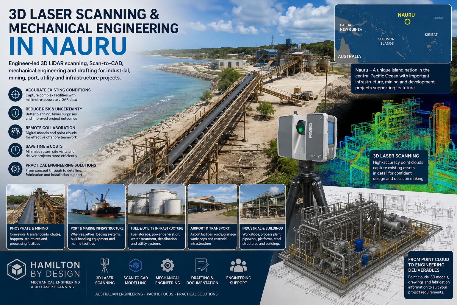


Explore additional Hamilton By Design services covering engineering-grade LiDAR scanning, Scan-to-CAD, mechanical engineering, manufacturing, ports, marine infrastructure and remote industrial projects.

3D Laser Scanning and Mechanical Engineering Nauru

3D laser scanning and mechanical engineering services for mining, port, utility, airport and industrial infrastructure projects in Nauru.

3D Laser Scanning and Mechanical Engineering Services in Nauru

Engineering-grade LiDAR scanning, Scan-to-CAD, mechanical engineering and drafting support for industrial, infrastructure and development projects across Nauru.

Hamilton By Design provides engineer-led 3D laser scanning, mechanical engineering, 3D CAD modelling and technical drafting services for projects in Nauru.

Working from Australia and travelling to project sites when required, we can support mining infrastructure, port and marine facilities, utilities, fuel-storage assets, industrial buildings, transport infrastructure and brownfield upgrade projects.

Our integrated approach combines accurate existing-condition capture with practical engineering knowledge. This helps project teams understand existing assets, develop reliable designs and reduce uncertainty before fabrication, installation or construction begins.

Engineering Support for Projects in Nauru

Nauru has a specialised industrial and infrastructure environment shaped by phosphate mining, marine transport, aviation, power generation, water supply, waste management and essential public infrastructure.

The islandโ€™s isolation also makes accurate project planning particularly important. Incorrect dimensions, unrecorded site conditions and fabrication errors can cause costly delays when replacement components, contractors and construction materials must be brought in from overseas.

Hamilton By Design can help project owners, consultants and contractors obtain accurate digital information before equipment is designed, manufactured or mobilised to Nauru.

Our services may support:

  • Phosphate-mining and materials-handling facilities
  • Conveyors, transfer points, chutes and hoppers
  • Port and marine infrastructure
  • Fuel-storage and transfer facilities
  • Power-generation and electrical infrastructure
  • Water-treatment and desalination facilities
  • Wastewater and waste-management infrastructure
  • Airport and transport facilities
  • Workshops and industrial buildings
  • Public infrastructure and government facilities
  • Coastal and climate-resilience projects
  • Land rehabilitation and redevelopment work

Nauruโ€™s infrastructure priorities have included transport, renewable energy, power, water, waste management, roads, marine access and aviation connectivity.

3D Laser Scanning in Nauru

Hamilton By Design uses terrestrial LiDAR technology to capture detailed three-dimensional information about existing buildings, equipment and infrastructure.

The scanner records millions of measured points, producing a coordinated point cloud that represents the visible surfaces of the asset or project area.

This information can be used to document:

  • Existing industrial facilities
  • Structural steel and access systems
  • Pipework and mechanical equipment
  • Conveyors and processing equipment
  • Port structures and loading facilities
  • Tanks, vessels and fuel infrastructure
  • Plant rooms and utility buildings
  • Roads, hardstands and external structures
  • Airport buildings and maintenance facilities
  • Areas proposed for refurbishment or redevelopment

Our engineering-grade 3D laser scanning services are intended to produce practical information for engineering, design, documentation and project deliveryโ€”not simply a visual point cloud.

Why Use LiDAR Scanning in Nauru?

Traditional site measurement can be difficult when facilities are congested, operational, elevated or located in areas with restricted access.

LiDAR scanning allows large amounts of dimensional information to be captured during a planned site visit. The resulting point-cloud data can then be reviewed remotely by designers, engineers, contractors and project stakeholders.

Potential benefits include:

  • Reduced dependence on manual site measurements
  • Fewer return visits to a remote project location
  • Improved confidence in existing dimensions
  • Better coordination between Australian and Nauruan project teams
  • Earlier identification of spatial constraints
  • Improved retrofit and brownfield design
  • Reduced fabrication and installation risk
  • More reliable tender and construction information
  • A permanent digital record of visible site conditions

For projects involving international travel and freight, reducing the need for repeat site attendance can provide considerable practical value.

Scan-to-CAD and Existing-Condition Modelling

Point-cloud data can be converted into useful engineering geometry through our 3D CAD modelling services.

Depending on the project requirements, deliverables may include:

  • Registered point clouds
  • Existing-condition 3D models
  • Scan-to-CAD models
  • Mechanical equipment models
  • Structural-steel models
  • Pipework and service models
  • General-arrangement drawings
  • Plans, elevations and sections
  • Interface and tie-in details
  • Dimensional verification reports
  • Fabrication drawings
  • STEP, SAT, Parasolid or native CAD files
  • DWG and DXF drawing files
  • E57, RCP, RCS or LAS point-cloud files

The level of modelling can be adjusted to suit the project. Some clients may require only a coordinated point cloud, while others may need a detailed design-ready model or fabrication drawing package.

Mechanical Engineering Services

Hamilton By Design can combine reality capture with practical mechanical engineering services.

This integrated workflow is particularly useful for existing facilities where original drawings are unavailable, incomplete or no longer represent the installed asset.

Mechanical engineering support may include:

  • Existing-condition engineering studies
  • Brownfield equipment modifications
  • Conveyor and materials-handling design
  • Chute, hopper and transfer-point design
  • Platforms, stairs, walkways and access systems
  • Machine guarding
  • Pipework and mechanical-layout development
  • Equipment supports and mounting arrangements
  • Reverse engineering of components
  • Maintenance and refurbishment planning
  • Design verification
  • Finite element analysis
  • Fabrication documentation
  • Installation and construction coordination

Because the site information and engineering design can be managed through the same workflow, important interfaces can be considered early in the project.

Phosphate and Materials-Handling Infrastructure

Phosphate mining has played a central role in Nauruโ€™s industrial history and has created a range of specialised materials-handling and export infrastructure.

Hamilton By Design can support existing phosphate and bulk-material facilities through:

  • Conveyor surveys
  • Transfer-chute measurement
  • Structural-steel documentation
  • Equipment-clearance assessment
  • Wear and erosion studies
  • Existing-condition modelling
  • Replacement component design
  • Access-platform and guarding design
  • Shutdown planning
  • Installation verification
  • As-built documentation

LiDAR scanning can be especially valuable where existing plant has been progressively altered and available drawings no longer reflect the current arrangement.

Port and Marine Infrastructure

As an island nation, Nauru depends heavily on reliable marine infrastructure for imported food, fuel, construction materials, machinery and other essential supplies.

Hamilton By Design can support port, wharf and marine-facility projects involving:

  • Cargo-handling infrastructure
  • Loading and unloading facilities
  • Marine structures
  • Pipework and fuel-transfer systems
  • Conveyors and bulk-material equipment
  • Access platforms and walkways
  • Structural interfaces
  • Existing-condition documentation
  • Modification and refurbishment projects
  • Clash detection and installation planning

A coordinated point cloud can allow offshore engineering and fabrication teams to inspect the project area digitally before materials or equipment are transported to the island.

Fuel, Power and Utility Infrastructure

Reliable power, fuel and water infrastructure is particularly important in remote island environments.

Hamilton By Design can provide scanning, modelling and engineering support for:

  • Diesel power-generation facilities
  • Fuel-storage tanks
  • Fuel-transfer pipework
  • Pump systems
  • Generator buildings
  • Water-treatment facilities
  • Desalination infrastructure
  • Pump stations
  • Wastewater facilities
  • Utility corridors
  • Renewable-energy projects
  • Equipment replacement and plant upgrades

Nauru has limited natural freshwater resources, which increases the importance of reliable water storage, treatment and desalination infrastructure.

Airport and Transport Infrastructure

Nauru International Airport is essential to the countryโ€™s connectivity and access to supplies, specialist personnel and services. Airport runway rehabilitation and associated road infrastructure have been identified as important national priorities.

Potential applications for 3D scanning and engineering include:

  • Airport maintenance buildings
  • Workshops and storage facilities
  • Plant rooms
  • Fuel infrastructure
  • Terminal refurbishment
  • Road and drainage interfaces
  • Existing structural documentation
  • Equipment installation planning
  • As-built verification
  • Contractor coordination

Remote Project Planning

A key benefit of creating a digital representation of a Nauru project site is the ability to continue engineering and design work after the field team has returned to Australia.

Project stakeholders can review the same coordinated dataset without repeatedly travelling to the site.

This can assist with:

  • Design reviews
  • Tender preparation
  • Contractor briefings
  • Fabrication planning
  • Construction sequencing
  • Equipment-clearance checks
  • Remote measurements
  • Interdisciplinary coordination
  • Maintenance planning
  • Future asset-management activities

The point cloud effectively becomes a measurable digital reference for the visible site conditions captured during the survey.

Typical Project Workflow

1. Project Definition

We review the asset, proposed work, required accuracy, site restrictions, travel requirements and intended deliverables.

2. Site Planning

A scanning plan is prepared around access, operational activities, safety requirements and the areas that must be documented.

3. LiDAR Data Capture

The project area is scanned from multiple coordinated positions to capture the required surfaces and equipment.

4. Point-Cloud Registration

Individual scans are processed and registered into a coordinated three-dimensional dataset.

5. CAD Modelling and Engineering

The registered point cloud is used to create existing-condition models, develop engineering designs or produce technical drawings.

6. Review and Delivery

Deliverables are checked against the agreed scope and supplied in formats suitable for the clientโ€™s engineering, construction or asset-management systems.

Engineering Experience Behind the Scan

Hamilton By Design is an Australian engineering and digital-engineering consultancy specialising in mechanical engineering, engineering-grade LiDAR scanning, reality capture, reverse engineering and industrial design.

Our background includes practical experience in:

  • Mechanical engineering
  • Fitting and machining
  • Fabrication
  • Mechanical drafting
  • Structural detailing
  • Materials handling
  • Industrial plant design
  • Mining and mineral processing
  • Manufacturing facilities
  • Port infrastructure
  • Water and wastewater facilities
  • Brownfield upgrades
  • Shutdown projects

This practical background helps us understand what information engineers, fabricators, maintainers and construction teams require from the scan.

Supporting Australian and Pacific Project Teams

Hamilton By Design can work with:

  • Nauruan government departments
  • Infrastructure authorities
  • Mining and phosphate operators
  • Port and logistics organisations
  • Utility providers
  • Australian engineering consultancies
  • Construction contractors
  • Equipment suppliers
  • Fabricators
  • Project-management teams
  • Development partners
  • Asset owners and facility operators

Services can be structured as scanning-only support, Scan-to-CAD documentation or a combined scanning, modelling and engineering package.

Discuss a Project in Nauru

Early project discussions help determine the most appropriate scanning coverage, engineering scope and deliverable format.

Useful information may include:

  • The project location
  • The type and approximate size of the asset
  • The reason for undertaking the survey
  • Available drawings or photographs
  • Required engineering deliverables
  • Site-access and induction requirements
  • Operational restrictions
  • Proposed travel dates
  • Required completion timeframe

Contact Hamilton By Design to discuss 3D laser scanning, Scan-to-CAD, mechanical engineering or drafting support for a project in Nauru.


Hamilton By Design logo displayed on a blue tilted rectangle with a grey gradient background

Contact Us – Talk To Us

Name
Would you like us to arrange a phone consultation for you?
Address

Our clients:























