Mechanical Engineering | 3D Scanning | 3D Modelling
Tag: Digital Engineering
Digital engineering covers the use of digital tools, data, and integrated workflows to plan, design, analyse, and deliver engineering projects. This tag brings together content showing how digital engineering combines 3D scanning, CAD modelling, engineering analysis, and data-driven processes to improve accuracy, coordination, and decision-making across industrial, infrastructure, and construction projects.
In brownfield projects, the highest return comes from applying engineering design effort at the point of change, supported by accurate point cloud data, rather than continuously updating a federated model.
The practical reality is:
Invest in engineering decisions, not in maintaining a model that becomes outdated faster than the plant changes.
Two Approaches
1. Model Maintenance–Centric (Navisworks)
Using Autodesk Navisworks Manage as an ongoing platform:
Capture and retain point cloud data as the primary asset
Model only what is being modified
Use CAD and drawings for fabrication and communication
Cost Drivers
Navisworks Model Maintenance
Initial model creation and federation
Continuous updates after modifications
Data conversion and reprocessing
Coordination meetings and clash resolution
Ongoing QA and model validation
Additional hidden costs include:
Model drift corrections
Rework due to mismatch with site conditions
Reliance on a limited number of trained users
Engineering-Driven Workflow
Targeted scanning where required
Point cloud processing and validation
Engineering design effort for modifications
Drawing and component model production
Additional benefits include:
Reusable scan data
No requirement to maintain a full plant model
Faster response to site-driven changes
Benefit Comparison
Navisworks model maintenance offers strong upfront coordination, particularly in greenfield projects, but suffers from degradation over time and high ongoing cost.
Engineering-driven workflows using point cloud data provide higher long-term accuracy, faster turnaround for small changes, and better alignment with real site conditions.
Line-of-Sight Reality
Point cloud data is inherently line-of-sight dependent. This means:
Only visible surfaces are captured
Occlusions result in gaps in the dataset
This limitation exists regardless of software platform.
Importing a point cloud into Navisworks does not improve data completeness or accuracy — it simply presents the same data in a different environment.
Practical Example
For a minor electrical upgrade:
Navisworks Approach
Update the federated model
Re-run coordination
Issue revised model
Proceed with installation
This introduces significant overhead for a simple task.
Engineering Approach
Review point cloud or site conditions
Confirm clearances
Design locally
Install
Update drawings if required
This approach is faster, lower cost, and aligned with how work is actually executed.
Where Navisworks Adds Value
Navisworks remains effective when:
Multiple disciplines are designing simultaneously
Large-scale coordination is required
Clash detection is critical
This typically applies to:
Greenfield projects
Major brownfield upgrades
It should be treated as a project-phase coordination tool, not a long-term data management system.
Recommended Strategy
Use point cloud data as the primary reference
Maintain raw and registered datasets (e.g. E57)
Model only critical interfaces and new work
Use drawings for formal deliverables
Apply Navisworks selectively where coordination is required
Final Position
In brownfield environments, value is created through engineering design and decision-making, not through continuous model maintenance.
One-Line Summary
Design what you’re changing. Scan what you’re keeping. Don’t model what you won’t maintain.
In modern engineering, accuracy is everything. Whether you are working in mining, manufacturing, infrastructure, or plant design, the difference between success and costly rework often comes down to how well you understand what has actually been built.
This is where laser scanning for engineering has become a critical tool.
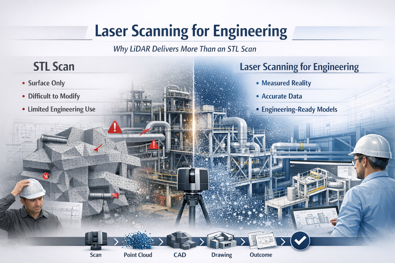
While many providers offer “3D scanning,” not all data is created equal. There is a significant difference between engineering-grade LiDAR point cloud data and basic STL mesh outputs. Understanding that difference can determine whether your project moves forward efficiently—or gets stuck in rework, assumptions, and redesign.
What is Laser Scanning for Engineering?
Laser scanning for engineering uses LiDAR (Light Detection and Ranging) technology to capture millions of precise measurements of a physical environment. The result is a high-density point cloud—a true digital representation of reality.
Unlike traditional measurement methods, LiDAR captures:
Complex geometry
Structural relationships
Equipment positioning
Real-world deviations from design
This data becomes the foundation for:
CAD modelling (SolidWorks, AutoCAD, Revit)
Engineering drawings
Clash detection
Retrofit and upgrade design
In short, it bridges the gap between design intent and as-built reality.
The Problem with STL-Based Scanning
Many scanning providers deliver outputs as STL, OBJ, or mesh files. While these formats are useful for visualisation or 3D printing, they fall short in engineering applications.
Key limitations of STL scans:
No intelligence – Meshes are just surfaces, not structured geometry
Difficult to modify – Not suitable for parametric design workflows
Poor for engineering drawings – Cannot easily generate sections, tolerances, or fabrication details
Heavy and inefficient – Large file sizes with limited usability
No clear chain of accuracy – Hard to verify measurement reliability
In practical terms, an STL file often becomes a dead-end deliverable—you can look at it, but you can’t engineer from it effectively.
Why LiDAR Point Clouds Are Built for Engineering
LiDAR-based laser scanning for engineering produces structured, measurable, and verifiable data that integrates directly into engineering workflows.
Key advantages:
1. True-to-Reality Accuracy
Point clouds capture millions of measured points, providing a high-confidence representation of the real world.
2. Direct CAD Integration
Data can be converted into:
Parametric 3D models
Fabrication-ready drawings
Plant layouts and assemblies
3. Supports Engineering Decisions
Engineers can:
Measure directly from the dataset
Validate clearances and tolerances
Design with confidence
4. Enables Retrofit and Brownfield Design
In existing plants, nothing is ever exactly “as drawn.” LiDAR ensures your design fits what is actually there, not what was intended years ago.
5. Reduces Risk and Rework
Accurate input data leads to:
Fewer site revisits
Reduced fabrication errors
Lower project costs
6. Maintains Chain of Custody
Engineering-grade scanning supports data governance, traceability, and verification—critical in legal, compliance, and high-risk environments.
Engineering vs Visualisation: A Critical Distinction
A key misunderstanding in the industry is assuming all 3D scanning is equal.
STL / Mesh Scanning → Visualisation Output
LiDAR Point Cloud → Engineering Input
If your goal is:
3D printing → STL may be enough
Engineering design, fabrication, or upgrades → LiDAR is essential
Real-World Application: Engineering in Practice
Across mining, manufacturing, and infrastructure, laser scanning for engineering is used to:
Capture conveyor systems before modification
Model structural steel for upgrades
Verify equipment installation
Design pipework and mechanical systems
Plan shutdown works with precision
Instead of guessing dimensions or relying on outdated drawings, engineers work from measured reality.
The Workflow That Delivers Results
A proper engineering workflow looks like this:
Scan → Register → Model → Detail → Deliver
Not:
Scan → Export STL → End
That difference defines whether you receive a usable engineering deliverable or just a digital artifact.
Laser scanning for engineering is not just about capturing data—it’s about enabling better engineering outcomes.
LiDAR-based point cloud data provides:
Accuracy
Usability
Engineering value
In contrast, STL-based scanning often limits what you can achieve.
If your project requires real design, real drawings, and real decisions, then the choice is clear:
Use laser scanning for engineering—not just scanning for appearance.
Artificial intelligence is being integrated into design platforms, automation is accelerating workflows, and digital engineering environments are becoming more connected than ever before. Tools such as SolidWorks are now introducing AI assistants like AURA, LEO, and Marie, promising smarter design, faster modelling, and improved decision-making.
But there is a fundamental issue that is often overlooked:
AI cannot design, validate, or optimise anything without a physical reference.
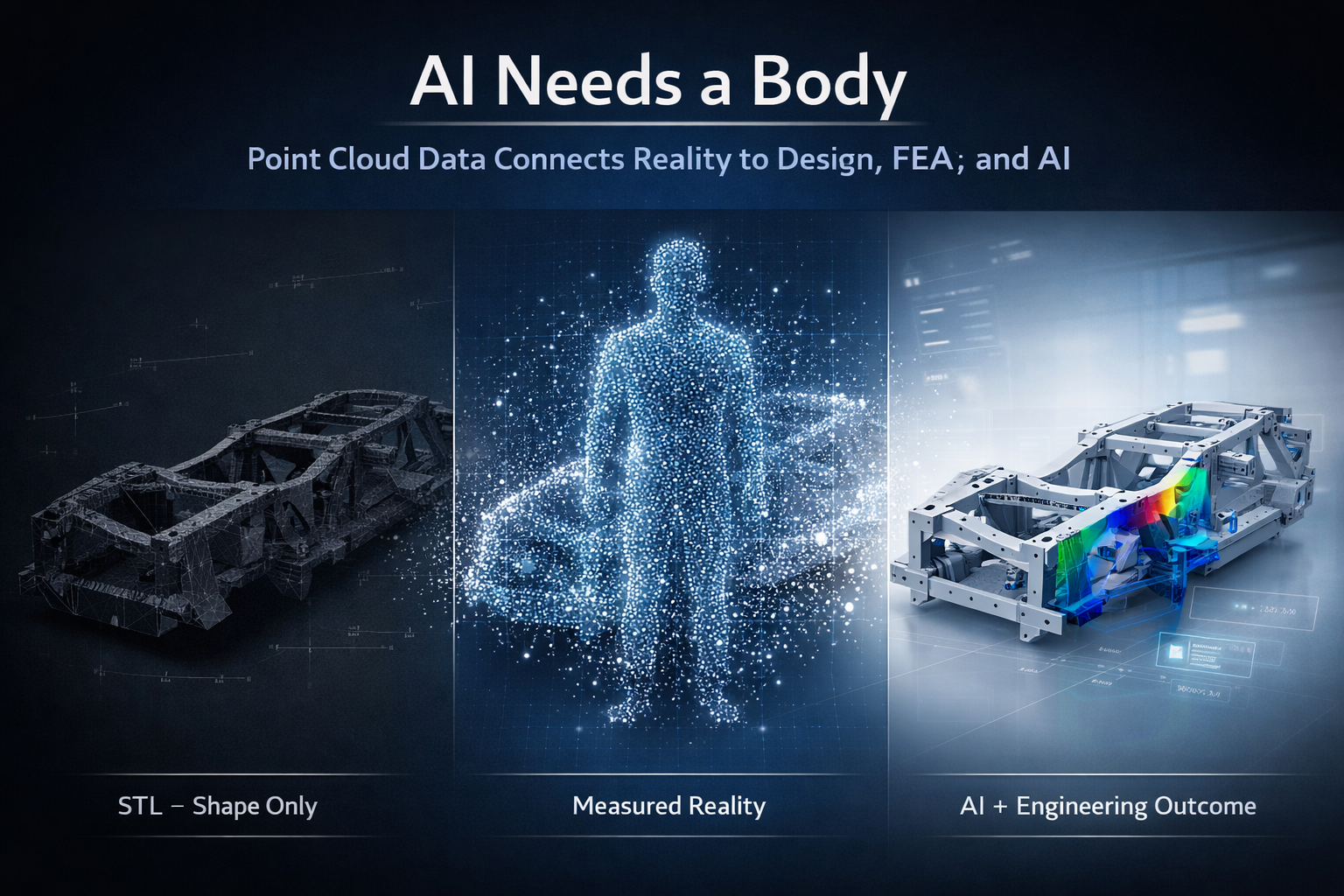
AI needs a body.
And in engineering, that body is real-world, measurable data.
3D point cloud scanning provides that foundation.
Gen 1, Gen 2, Gen 3 – The Evolution of Engineering
Engineering workflows can be broadly understood in three stages: Gen 1, Gen 2, and Gen 3.
Gen 1 was manual. Tape measures, site sketches, and experience-driven decisions formed the basis of design. While effective for its time, it relied heavily on interpretation and often resulted in rework due to incomplete data.
Gen 2 introduced CAD platforms such as SolidWorks, Autodesk Inventor, Autodesk Fusion, and Onshape. This enabled parametric modelling, faster iteration, and improved documentation. However, Gen 2 introduced a new problem—designs were often disconnected from reality. Models were built based on assumptions, outdated drawings, or incomplete site data.
Even when scanning was introduced, the workflow often stopped at STL or OBJ files. These formats are visual representations only. They are static, faceted, and lack the structure required for engineering.
Gen 3 represents the shift to reality-based engineering. This is where point cloud scanning, CAD, FEA, AI, and lifecycle management systems all connect. The key difference is that models are no longer based on assumptions—they are derived from measured reality.
The Problem With STL Workflows
STL files are commonly produced by handheld or metrology-grade scanners. They are easy to generate and provide a visually accurate representation of a component.
However, an STL file is a triangulated mesh. It contains no features, no relationships, and no design intent. It is a surface approximation made up of flat facets.
This creates a major limitation.
An STL file can show what something looks like, but it cannot define how it functions, how it should be modified, or how it should be manufactured.
Why FEA on STL Is Not Best Practice
It is technically possible to run Finite Element Analysis (FEA) on an STL file, but it is not considered best practice.
The reasons are straightforward.
The geometry is not true. Surfaces are faceted, holes are not perfect circles, and edges are broken into triangles. This makes it difficult to apply loads and boundary conditions accurately.
Because the STL is already a mesh, FEA introduces a second mesh on top of it. This reduces control over element quality and can affect convergence and accuracy.
Most importantly, the results are based on an approximation rather than engineered geometry.
You are analysing a surface representation, not a design.
For engineering decisions, this creates risk. Results become difficult to verify, defend, or repeat.
AI Has the Same Limitation
AI assistants such as AURA, LEO, and Marie are designed to work inside CAD environments. They rely on structured, parametric data to assist with modelling, optimisation, and decision-making.
They are highly effective when working with:
Defined features
Parametric relationships
Clean geometry
But when given an STL file, AI faces the same problem as the engineer.
There are no features to interpret, no constraints to follow, and no design intent to understand. The data is simply a collection of triangles.
As a result:
AI cannot meaningfully design or optimise from an STL file.
It can attempt to approximate geometry, but it cannot guarantee accuracy, intent, or engineering reliability.
AI Needs a Body
AI is often described as the brain of the future engineering workflow.
But a brain alone is not enough.
Without a body:
There is no spatial context
No physical reference
No connection to reality
In engineering, the body is the physical asset captured in digital form.
This is where point cloud scanning becomes critical.
Point Cloud – The Body for Engineering and AI
Point cloud data captures millions of measured points in three-dimensional space. Each point represents a real-world coordinate.
This provides:
True geometry
Accurate spatial relationships
Complete environmental context
Unlike STL files, point clouds are not simplified or interpreted. They represent measured reality.
From this data, engineers can:
Extract accurate dimensions
Fit planes, cylinders, and features
Build parametric CAD models
Maintain traceability back to the original scan
This creates a reliable foundation for both engineering and AI.
The Correct Engineering Workflow
A robust, engineering-grade workflow follows a clear sequence:
Scan → Point Cloud → CAD Model → FEA → AI → Engineering Outcome
Each step adds value.
The scan captures reality. The point cloud preserves it. The CAD model structures it. FEA validates it. AI enhances it.
Without the point cloud, the entire process loses its connection to reality.
Vehicle Chassis Example
Consider the development or modification of a vehicle chassis.
Using an STL-based workflow, the process typically involves rebuilding geometry from a mesh, applying FEA to an approximation, and attempting to optimise the design without a reliable reference. This introduces risk in alignment, load paths, and final fitment.
Using a point cloud-based workflow, the chassis is scanned and modelled directly from measured data. FEA is applied to true geometry, and AI tools such as AURA, LEO, and Marie can assist in refining and optimising the design.
The result is accurate, repeatable, and ready for manufacturing.
Digital Twin, PLM, and the 3D Environment
Point cloud data also supports broader engineering systems, including Digital Mock-Up (DMU), Product Data Management (PDM), and Product Lifecycle Management (PLM).
These systems rely on a single source of truth.
Point cloud data provides that truth by ensuring alignment between the digital model and the physical asset.
This enables:
Lifecycle tracking
Design validation
Ongoing updates and modifications
It also supports Digital Twin environments, where the physical and digital worlds remain connected over time.
Manufacturing in Australia
For manufacturing, accuracy is critical.
Point cloud-driven workflows ensure that:
Components fit as intended
Drawings reflect real-world conditions
Rework is minimised
Fabrication is efficient
This is particularly important for local manufacturing in Australia, where precision and reliability directly impact cost and delivery.
The Bottom Line
It is not best practice to run FEA on an STL file. It is not effective to design from an STL file. And it is unrealistic to expect AI to compensate for poor input data.
STL files provide a visual reference, but they do not provide a foundation for engineering.
AI is a powerful tool, but it cannot operate without accurate, structured data.
AI cannot fix a workflow that starts with the wrong data.
Final Thought
Engineering is evolving.
Gen 1 was manual. Gen 2 was digital. Gen 3 is reality-based and AI-assisted.
AI is not the starting point. Data is.
And in modern engineering:
AI needs a body. Point cloud scanning is that body.
In the world of 3D scanning, there is often confusion around what type of data is actually useful for engineering. Many providers offer high-accuracy scanning using metrology-grade equipment, yet the final deliverable is often limited to STL or OBJ files.
The question is simple: If the data cannot be used inside your CAD system, what is its real value?
The Rise of Metrology-Grade Scanning
Modern handheld scanners are incredibly capable. They can capture fine detail, achieve high accuracy, and generate dense surface representations of components. These systems are often used in reverse engineering, product design, and inspection workflows.
They are frequently marketed as “metrology-grade,” and in terms of capture capability, that claim is valid. These scanners can measure to very tight tolerances and produce highly detailed digital representations.
However, the real issue is not how the data is captured. It is how the data is delivered and how it integrates into engineering workflows.
Capturing accurate data is only the first step. The true value lies in whether that data can be used to design, modify, verify, and manufacture real-world components.
STL and OBJ – A Surface, Not a Solution
STL and OBJ files are mesh-based formats. They represent the surface of an object using thousands or millions of triangles stitched together to form a 3D shape.
These files are useful for:
Visualisation
3D printing
Basic reference and communication
They are fast to generate and easy to share, which is why many scanning providers stop at this stage.
However, they come with significant limitations:
No parametric geometry
No selectable engineering features
No design intent
Difficult to dimension accurately
Cannot drive CAD models effectively
A mesh file is essentially a visual representation, not an engineering model.
In simple terms:
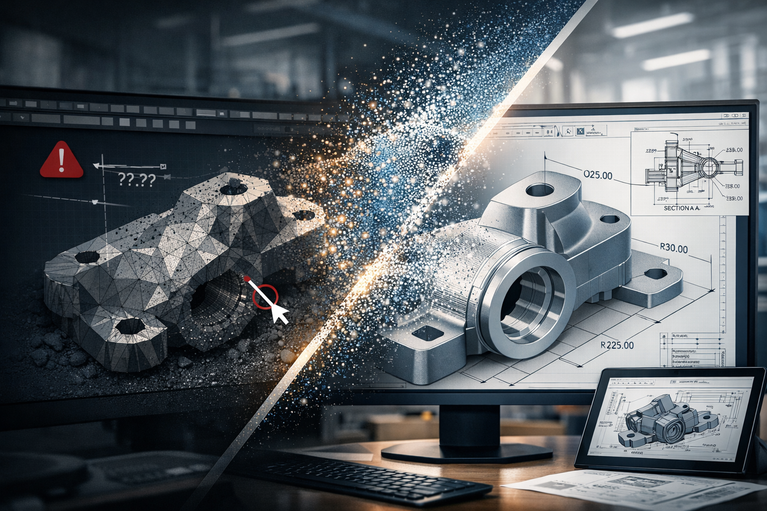
An STL file shows what something looks like, but not how to design, modify, or manufacture it.
Once the data is converted into a mesh, it is often smoothed, simplified, and processed. This means the original measured data is no longer fully preserved, and any measurements taken from the mesh are based on an interpreted surface rather than raw coordinates.
Engineering Happens in CAD
Real engineering work takes place inside platforms such as SolidWorks, Autodesk Inventor, Autodesk Fusion, and Onshape.
These tools are built around:
Parametric modelling
Feature-based design
Relationships and constraints
Editable geometry
They rely on identifiable features such as:
Planes
Cylinders
Holes
Edges and faces
Mesh files do not contain this level of intelligence. As a result, they cannot be easily used to:
Modify or optimise designs
Perform engineering calculations or simulations
Generate fabrication-ready drawings
Maintain consistency across revisions
This creates a disconnect:
You can measure on the scanner, but you cannot effectively design in CAD.
And if design cannot happen in CAD, the workflow breaks down.
The Advantage of Point Cloud Data
Point cloud data, typically delivered in formats such as E57 or RCP, captures real-world coordinates directly from the scan. Each point represents a measurable location in 3D space.
This is fundamentally different from a mesh.
Point clouds provide:
True measured data (not interpreted surfaces)
High-density spatial accuracy
Full capture of the environment or component
The ability to revisit and re-measure at any time
This enables engineers to:
Extract accurate dimensions directly from real-world data
Fit geometry (planes, cylinders, centre lines) inside CAD
Validate designs against existing conditions
Maintain traceability and confidence in the data
Point clouds form the foundation for engineering-grade modelling, not just visual representation.
From Scan to Engineering Outcome
At Hamilton By Design, the focus is not just on capturing data, but on delivering usable engineering outcomes.
Our workflow is:
Scan → Point Cloud → CAD Model → Engineering Drawings
This ensures the data can be:
Measured inside CAD
Verified and checked against real conditions
Modified to suit design requirements
Used for fabrication, installation, and real-world implementation
This approach bridges the gap between reality and design.
It turns captured data into something that engineers, fabricators, and project teams can actually use.
Like-for-Like vs Design Flexibility
If your requirement is a like-for-like digital representation of an object, mesh files such as STL or OBJ may be sufficient.
They provide a quick and effective way to visualise shape and form.
However, if your goal is to:
Modify a design
Integrate with existing infrastructure
Produce engineering drawings
Support fabrication or installation
Then flexibility becomes critical.
If you’re looking for like-for-like, mesh will get you there. If you’re looking for a flexible design tool, point cloud is the answer.
The Bottom Line
Metrology-grade scanners can capture extremely accurate data. But if that data is delivered only as an STL or OBJ file, its value is significantly limited within an engineering context.
True value comes from transforming scan data into something that works inside CAD and supports real-world outcomes.
Mesh files deliver a shape. Point clouds deliver a foundation for engineering.
In Sydney’s high-cost construction and industrial market, mistakes are expensive.
With Australian labour rates among the highest in the region — and Sydney operating at premium commercial rates — the cost of rework, design clashes, undocumented variations, and inaccurate site data can quickly exceed the cost of doing things correctly the first time.
That’s where 3D scanning combined with engineering governance becomes essential.
Why Sydney Projects Need Engineering Governance
Sydney projects are:
Brownfield upgrades in live facilities
Tight commercial refurbishments
Infrastructure constrained by existing services
Industrial sites with layered legacy modifications
Without a verified “single source of truth,” teams rely on outdated drawings, assumptions, or partial information.
That leads to:
On-site clashes
Fabrication errors
Delays waiting for redesign
Contractual disputes
Escalating labour costs
In a market where skilled labour can exceed $120–$200+ per hour once overheads and compliance are included, one preventable mistake can cost tens of thousands of dollars.
Rework is not just frustrating — it’s financially destructive.
What 3D Scanning Actually Solves
High-accuracy 3D laser scanning captures:
Structural steel
Services (mechanical, electrical, hydraulic)
Plant and equipment
Spatial constraints
Floor levels and tolerances
Instead of relying on legacy drawings, you design from reality capture data.
But scanning alone is not enough.
The Missing Link: Engineering Governance
Raw point clouds don’t protect your project.
Governance does.
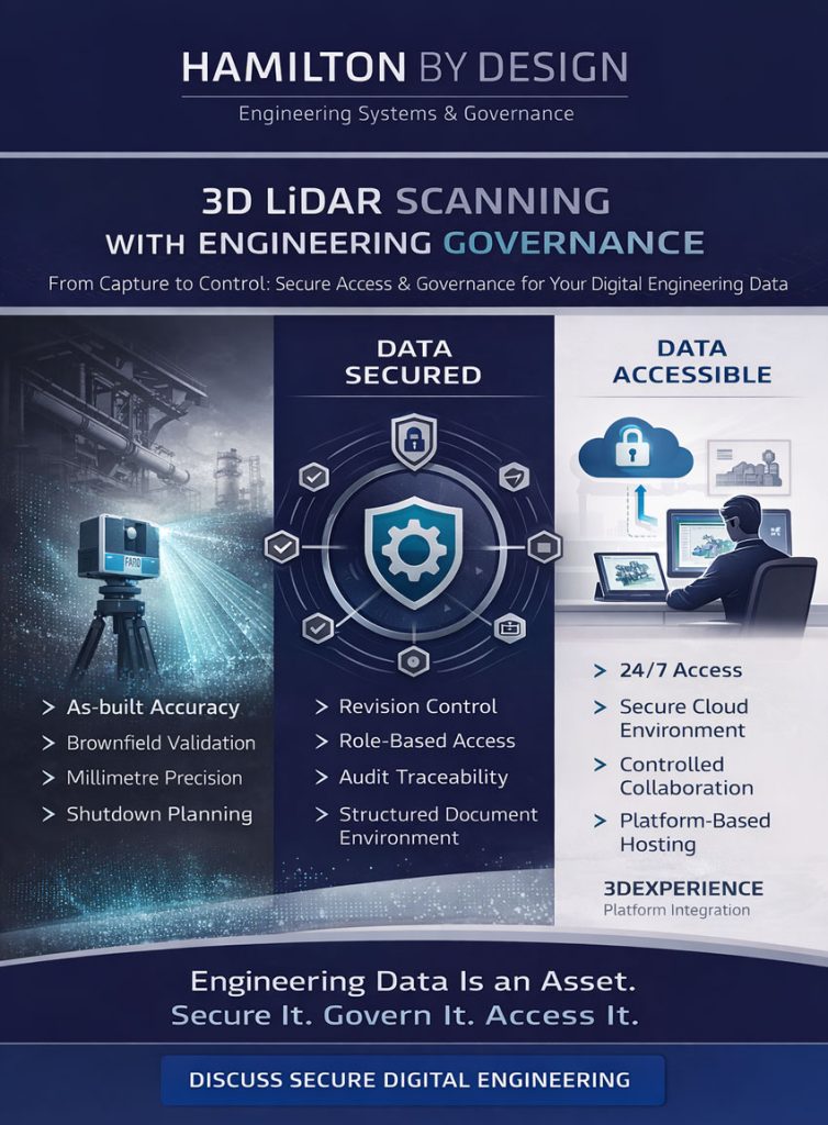
Engineering governance ensures:
✔ Controlled data access ✔ Revision management ✔ Clear drawing issue status (IFR / IFA / IFC) ✔ Structured documentation ✔ Auditability and traceability ✔ Secure collaboration between contractors
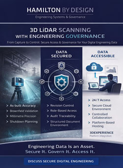
When 3D scanning is integrated into a governed digital environment, your project moves from assumption-based to evidence-based engineering.
The Cost of Rework in Sydney
Let’s be clear:
In Australia, rework costs are amplified by:
High skilled labour rates
Strict compliance requirements
Complex subcontractor structures
Extended programme impacts
Safety and shutdown penalties
A fabrication error might not just mean remaking steel — it can mean:
Crane rebooking
Night shift penalties
Programme delay claims
Supervisor time
Engineering redesign
In many Sydney industrial environments, a single clash can cost more than the entire 3D scan.
That’s why governance-backed scanning is not an expense — it’s risk insurance.
Sydney Doesn’t Need More Data. It Needs Better Control.
Hamilton By Design provides engineering-led 3D scanning, LiDAR scanning, mechanical engineering and digital engineering services throughout Sydney and Greater Sydney.
Explore our related Sydney services:
3D Scanning Sydney – Engineering-grade terrestrial laser scanning, as-built surveys and point cloud capture for industrial, infrastructure and commercial projects.
Reality Capture Sydney – High-accuracy reality capture, digital twins, asset documentation and engineering-grade site verification.
Scan to CAD Sydney – Convert point cloud data into AutoCAD, SolidWorks, Inventor and other engineering-ready CAD deliverables.
Point Cloud Modelling Sydney– Engineering-grade point cloud processing, clash detection, as-built verification and 3D modelling.
Mechanical Engineering Sydney – Mechanical design, plant upgrades, materials handling systems, conveyors, chutes, platforms and engineering support.
Structural Drafting Sydney– Structural steel drafting, fabrication drawings, GA drawings, workshop detailing and as-built documentation.
Hamilton By Design supports projects throughout Sydney CBD, Parramatta, Liverpool, Penrith, Blacktown, Chatswood, Alexandria, Mascot, Newcastle and the Central Coast.
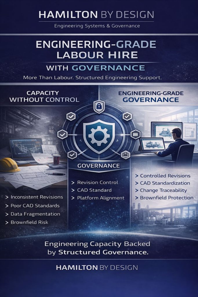
Engineering-Grade Labour Hire with Governance | Hamilton By Design
In heavy industry, mining, manufacturing and infrastructure, labour hire is common. But too often, it solves only one problem — short-term capacity.
It does not solve control.
Drawings are produced. Models are updated. Changes are made. Yet without structured governance, projects quietly lose alignment.
At Hamilton By Design, we approach labour hire differently. We provide engineering-grade secondment backed by governance discipline.
The Hidden Risk in Traditional Labour Hire
Most labour hire arrangements focus on hours and availability.
What is often overlooked:
Inconsistent CAD standards
Poor revision control
Unclear drawing issue status (IFR / IFA / IFC)
Fragmented contractor inputs
Brownfield upgrades corrupting master records
Loss of traceability during fast-tracked works
The result?
Capacity increases — but risk increases with it.
Engineering environments, especially live operating sites, cannot afford that.
What Does “Engineering Grade” Actually Mean?
Engineering-grade secondment is not simply providing a drafter or designer.
It means supplying personnel who understand:
Configuration control
Document lifecycle management
Industrial compliance requirements
Change management discipline
Digital environment structure
Risk in operational facilities
It means embedding someone who works within a governance framework — not outside of it.
Governance Is the Difference
Engineering governance ensures:
Drawings reflect physical site reality
Revisions are auditable
Contractors work from approved documentation
Brownfield upgrades maintain data integrity
Digital models remain a reliable single source of truth
Risk is reduced before construction begins
Governance protects capital investment.
Without it, labour hire becomes a short-term patch that creates long-term technical debt.
Brownfield Environments Demand More
Live operating facilities are complex.
They involve:
Multi-vendor interfaces
Progressive isolation of operational zones
Legacy drawings
Unknown modifications
Production pressure
In these environments, uncontrolled changes can introduce safety, operational and financial risk.
Hamilton By Design brings governance discipline into the labour hire model — ensuring upgrades, modifications and expansions are managed within structured engineering control.
Engineering Secondment with Digital Alignment
Our engineering-grade secondment integrates with structured digital environments, including:
Controlled CAD standards
Managed drawing registers
Platform-based collaboration environments
Revision tracking workflows
Vendor drawing review protocols
Rather than simply placing a resource on site, we align that resource with a defined governance system.
That alignment protects the project — and the client.
More Than Labour. Structured Engineering Support.
Hamilton By Design delivers:
Engineering governance support
CAD and drawing control oversight
Brownfield upgrade discipline
Data integrity protection
Digital continuity across project stages
This is labour hire redefined.
It is engineering capacity supported by structure, accountability and technical leadership.
When Is Engineering-Grade Labour Hire Required?
Complex brownfield upgrades
Live operational facilities
Multi-contractor environments
Digital transformation programs
CAD standardisation projects
Projects requiring traceable revision control
If your project needs more than drafting — if it needs structured engineering control — Hamilton By Design delivers engineering-grade secondment aligned with governance, compliance and operational continuity.
To provide the best experiences, we use technologies like cookies to store and/or access device information. Consenting to these technologies will allow us to process data such as browsing behaviour or unique IDs on this site. Not consenting or withdrawing consent, may adversely affect certain features and functions.
Functional
Always active
The technical storage or access is strictly necessary for the legitimate purpose of enabling the use of a specific service explicitly requested by the subscriber or user, or for the sole purpose of carrying out the transmission of a communication over an electronic communications network.
Preferences
The technical storage or access is necessary for the legitimate purpose of storing preferences that are not requested by the subscriber or user.
Statistics
The technical storage or access that is used exclusively for statistical purposes.The technical storage or access that is used exclusively for anonymous statistical purposes. Without a subpoena, voluntary compliance on the part of your Internet Service Provider, or additional records from a third party, information stored or retrieved for this purpose alone cannot usually be used to identify you.
Marketing
The technical storage or access is required to create user profiles to send advertising, or to track the user on a website or across several websites for similar marketing purposes.