

Engineering is entering a new phase.
Artificial intelligence is being integrated into design platforms, automation is accelerating workflows, and digital engineering environments are becoming more connected than ever before. Tools such as SolidWorks are now introducing AI assistants like AURA, LEO, and Marie, promising smarter design, faster modelling, and improved decision-making.
But there is a fundamental issue that is often overlooked:
AI cannot design, validate, or optimise anything without a physical reference.
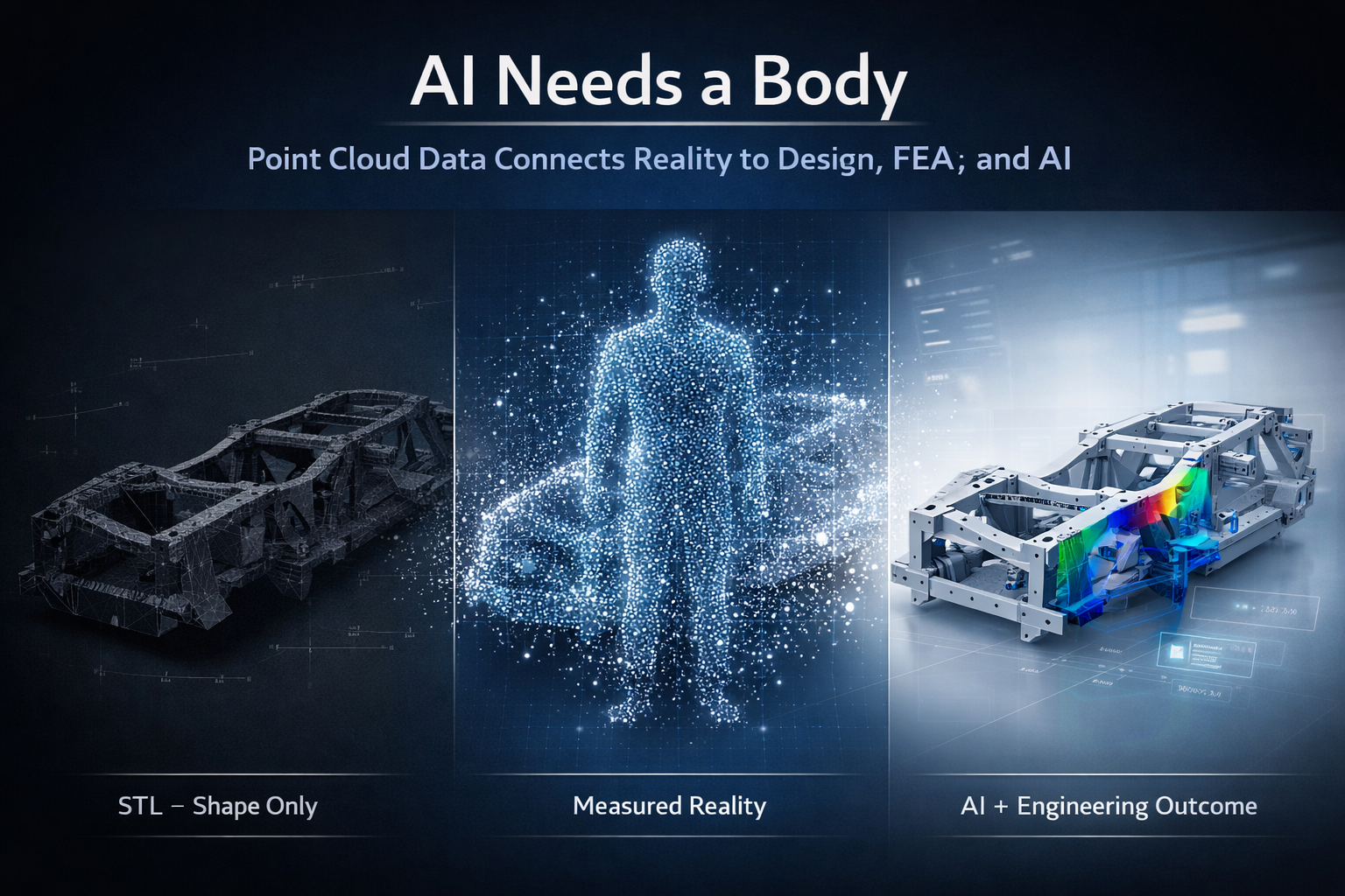
AI needs a body.
And in engineering, that body is real-world, measurable data.
3D point cloud scanning provides that foundation.


Gen 1, Gen 2, Gen 3 – The Evolution of Engineering
Engineering workflows can be broadly understood in three stages: Gen 1, Gen 2, and Gen 3.
Gen 1 was manual. Tape measures, site sketches, and experience-driven decisions formed the basis of design. While effective for its time, it relied heavily on interpretation and often resulted in rework due to incomplete data.
Gen 2 introduced CAD platforms such as SolidWorks, Autodesk Inventor, Autodesk Fusion, and Onshape. This enabled parametric modelling, faster iteration, and improved documentation. However, Gen 2 introduced a new problem—designs were often disconnected from reality. Models were built based on assumptions, outdated drawings, or incomplete site data.
Even when scanning was introduced, the workflow often stopped at STL or OBJ files. These formats are visual representations only. They are static, faceted, and lack the structure required for engineering.
Gen 3 represents the shift to reality-based engineering. This is where point cloud scanning, CAD, FEA, AI, and lifecycle management systems all connect. The key difference is that models are no longer based on assumptions—they are derived from measured reality.
The Problem With STL Workflows
STL files are commonly produced by handheld or metrology-grade scanners. They are easy to generate and provide a visually accurate representation of a component.
However, an STL file is a triangulated mesh. It contains no features, no relationships, and no design intent. It is a surface approximation made up of flat facets.
This creates a major limitation.
An STL file can show what something looks like, but it cannot define how it functions, how it should be modified, or how it should be manufactured.
Why FEA on STL Is Not Best Practice
It is technically possible to run Finite Element Analysis (FEA) on an STL file, but it is not considered best practice.
The reasons are straightforward.
The geometry is not true. Surfaces are faceted, holes are not perfect circles, and edges are broken into triangles. This makes it difficult to apply loads and boundary conditions accurately.
Because the STL is already a mesh, FEA introduces a second mesh on top of it. This reduces control over element quality and can affect convergence and accuracy.
Most importantly, the results are based on an approximation rather than engineered geometry.
You are analysing a surface representation, not a design.
For engineering decisions, this creates risk. Results become difficult to verify, defend, or repeat.
AI Has the Same Limitation
AI assistants such as AURA, LEO, and Marie are designed to work inside CAD environments. They rely on structured, parametric data to assist with modelling, optimisation, and decision-making.
They are highly effective when working with:
- Defined features
- Parametric relationships
- Clean geometry
But when given an STL file, AI faces the same problem as the engineer.
There are no features to interpret, no constraints to follow, and no design intent to understand. The data is simply a collection of triangles.
As a result:
AI cannot meaningfully design or optimise from an STL file.
It can attempt to approximate geometry, but it cannot guarantee accuracy, intent, or engineering reliability.
AI Needs a Body
AI is often described as the brain of the future engineering workflow.
But a brain alone is not enough.
Without a body:
- There is no spatial context
- No physical reference
- No connection to reality
In engineering, the body is the physical asset captured in digital form.
This is where point cloud scanning becomes critical.
Point Cloud – The Body for Engineering and AI
Point cloud data captures millions of measured points in three-dimensional space. Each point represents a real-world coordinate.
This provides:
- True geometry
- Accurate spatial relationships
- Complete environmental context
Unlike STL files, point clouds are not simplified or interpreted. They represent measured reality.
From this data, engineers can:
- Extract accurate dimensions
- Fit planes, cylinders, and features
- Build parametric CAD models
- Maintain traceability back to the original scan
This creates a reliable foundation for both engineering and AI.
The Correct Engineering Workflow
A robust, engineering-grade workflow follows a clear sequence:
Scan → Point Cloud → CAD Model → FEA → AI → Engineering Outcome
Each step adds value.
The scan captures reality.
The point cloud preserves it.
The CAD model structures it.
FEA validates it.
AI enhances it.
Without the point cloud, the entire process loses its connection to reality.
Vehicle Chassis Example
Consider the development or modification of a vehicle chassis.
Using an STL-based workflow, the process typically involves rebuilding geometry from a mesh, applying FEA to an approximation, and attempting to optimise the design without a reliable reference. This introduces risk in alignment, load paths, and final fitment.
Using a point cloud-based workflow, the chassis is scanned and modelled directly from measured data. FEA is applied to true geometry, and AI tools such as AURA, LEO, and Marie can assist in refining and optimising the design.
The result is accurate, repeatable, and ready for manufacturing.
Digital Twin, PLM, and the 3D Environment
Point cloud data also supports broader engineering systems, including Digital Mock-Up (DMU), Product Data Management (PDM), and Product Lifecycle Management (PLM).
These systems rely on a single source of truth.
Point cloud data provides that truth by ensuring alignment between the digital model and the physical asset.
This enables:
- Lifecycle tracking
- Design validation
- Ongoing updates and modifications
It also supports Digital Twin environments, where the physical and digital worlds remain connected over time.
Manufacturing in Australia
For manufacturing, accuracy is critical.
Point cloud-driven workflows ensure that:
- Components fit as intended
- Drawings reflect real-world conditions
- Rework is minimised
- Fabrication is efficient
This is particularly important for local manufacturing in Australia, where precision and reliability directly impact cost and delivery.
The Bottom Line
It is not best practice to run FEA on an STL file. It is not effective to design from an STL file. And it is unrealistic to expect AI to compensate for poor input data.
STL files provide a visual reference, but they do not provide a foundation for engineering.
AI is a powerful tool, but it cannot operate without accurate, structured data.
AI cannot fix a workflow that starts with the wrong data.
Final Thought
Engineering is evolving.
Gen 1 was manual.
Gen 2 was digital.
Gen 3 is reality-based and AI-assisted.
AI is not the starting point. Data is.
And in modern engineering:
AI needs a body.
Point cloud scanning is that body.
Our Clients


