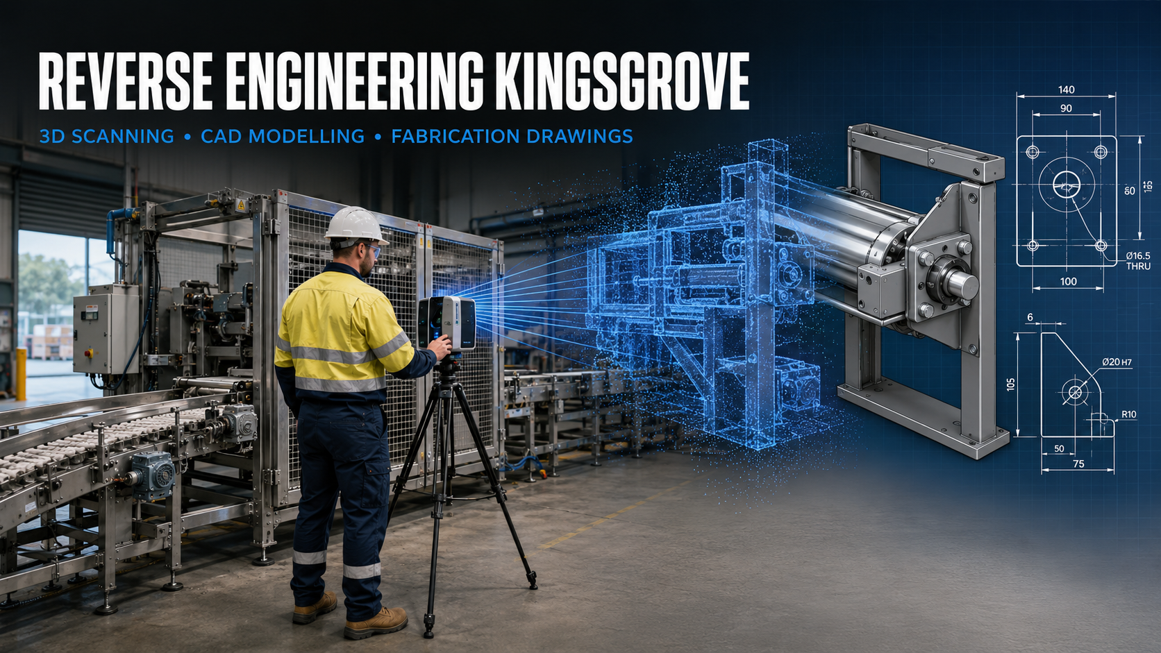
Reverse Engineering Brookvale | 3D Scanning & CAD

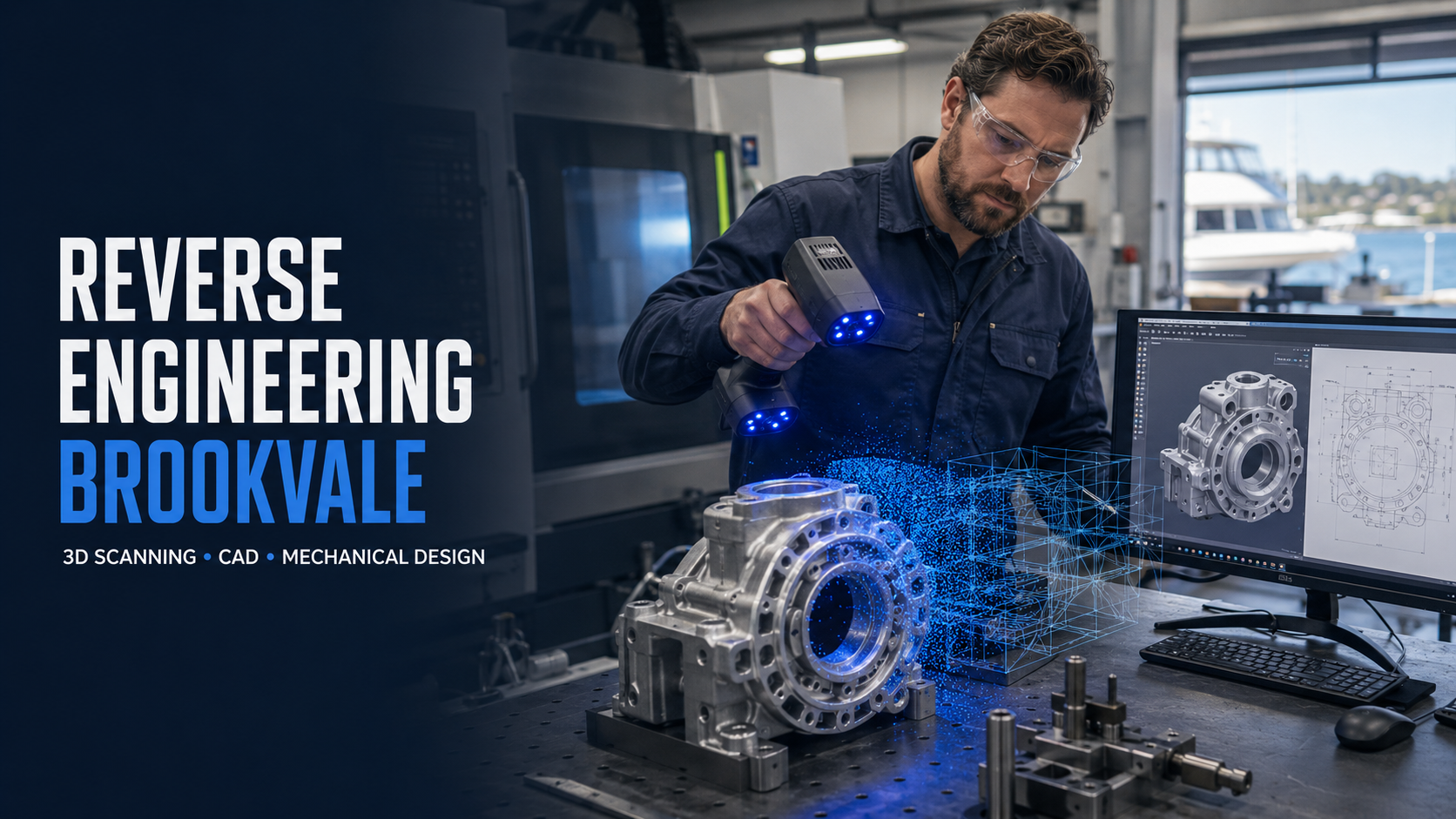
Mechanical engineer 3D scanning a machinery component for reverse engineering and CAD modelling in Brookvale, NSW.

Reverse Engineering Brookvale: 3D Scanning, Mechanical Design and Manufacturing Documentation

Blue 3D LiDAR scanner icon on a tripod with scanning waves

Brookvale is one of the Northern Beachesโ€™ most important employment and industrial centres. Although the suburb is widely associated with retailing and Warringah Mall, its broader economy includes precision manufacturing, CNC machining, electronics, marine technology, food and beverage production, steel supply, warehousing, surf products and specialised machinery.

These industries frequently depend on physical equipment and components for which accurate engineering information may be incomplete, outdated or unavailable. A machine may have been modified several times without its drawings being updated. An imported component may no longer be supported by its original manufacturer. A prototype may exist physically but not as an editable three-dimensional model. In each of these situations, reverse engineering provides a practical way to recover the necessary technical information.

Hamilton By Design provides reverse engineering and 3D scanning services in Sydney to help manufacturers, machinery owners, maintenance contractors and product developers convert existing physical assets into useful engineering data. Depending on the project, the resulting information may include component scans, point clouds, three-dimensional CAD models, fabrication drawings, machining information and dimensional inspection records.

Brookvaleโ€™s changing industrial character

Brookvale developed as an industrial centre during the twentieth century and remains the Northern Beachesโ€™ largest employment hub. Its industrial areas accommodate an unusually diverse mixture of production, workshop, warehouse, retail and creative activities.

The Brookvale Structure Plan adopted by Northern Beaches Council identifies the suburb as an employment and innovation centre. It seeks to preserve important industrial land while encouraging higher-value technical, commercial and creative employment. The plan anticipates approximately 900 additional jobs and recognises the importance of Brookvaleโ€™s industrial and urban-services land to the wider Northern Beaches economy.

The precinct already demonstrates this industrial diversity. Sorensen Engineering operates precision CNC manufacturing, robotics, prototyping and product-development facilities in Brookvale. Benbro Electronics manufactures power and communications products, including electronic assemblies, enclosures and cable harnesses. Electrotech Australia supplies and supports marine navigation and communications equipment, while Symetec supports food-processing machinery and spare parts.

Brookvale also contains brewing and distilling operations, including the 4 Pines Brewery headquarters and Manly Spirits Co. Distillery. Steel suppliers, automotive workshops, surfboard manufacturers, fabricators, food businesses and warehouse operators add further complexity to the local economy.

This combination creates opportunities for specialised engineering support. While the products differ, many businesses face the same fundamental problem: they need accurate information about an existing component, machine or facility before they can confidently repair, reproduce, modify or replace it.

What is reverse engineering?

Reverse engineering is the systematic process of examining an existing product or machine to understand its geometry, interfaces, materials and intended function. The objective is not simply to create a visual copy. Effective reverse engineering produces engineering information that can support decisions about manufacture, maintenance, design improvement and safety.

A typical project may begin with engineering-grade 3D scanning or detailed component scanning. The captured data records the observable surfaces of the component or installation. This data is then processed, reviewed and converted into suitable CAD geometry.

The required output depends on the clientโ€™s purpose. A visualisation model may only need to represent the overall shape. A replacement component may require careful reconstruction of mounting faces, shaft centres, hole patterns, fits, clearances and other functional features. A fabrication project may require a general arrangement, individual part drawings, weld details, materials and a bill of materials.

Hamilton By Designโ€™s point-cloud-to-CAD services in Sydney connect physical measurement with practical mechanical design and drafting. This means the scan is treated as engineering source data rather than as the final deliverable.

Why Brookvale businesses may need reverse engineering

Obsolete or unavailable replacement parts

Industrial machinery often remains operational for much longer than the commercial life of its individual components. Bearings and standard fasteners may remain available, but proprietary housings, covers, brackets, shafts, impellers, guides and change parts may no longer be supplied.

An obsolete component can potentially be scanned and reconstructed to create a controlled CAD model and manufacturing drawing. Where appropriate, the part can also be reviewed for improved materials, easier manufacture or increased service life.

Hamilton By Designโ€™s experience with reverse engineering replacement components in Sydney illustrates how physical parts can be converted into repeatable engineering records. The same general workflow can be applied to manufacturing, marine, food-processing and specialised product components in Brookvale.

Reverse engineering does not remove the need for engineering judgement. Material grade, heat treatment, surface finish, loading, tolerances and failure history may not be visible in a scan. These requirements must be established from operating information, testing, client records or an appropriate engineering assessment.

Missing or unreliable drawings

Many workshops possess machinery that has been moved, repaired or modified repeatedly. Drawings may represent the equipment when it was first installed but not its current configuration. In other cases, workshop knowledge may exist only in handwritten dimensions or in the experience of individual employees.

3D laser scanning for industrial plants in Sydney can capture the current spatial arrangement of machinery, structures, services and access areas. The resulting point cloud provides a permanent record of the observed condition at the time of scanning.

This information can support equipment relocation, new production lines, conveyor modifications, access improvements and installation planning. It can also reduce dependence on repeated site measurement and preserve knowledge that could otherwise be lost when personnel or contractors change.

Components that are difficult to measure manually

Curved housings, castings, moulds, composite products and fabricated transitions can be difficult to describe using rulers and callipers alone. Manual measurement remains important, particularly for critical functional dimensions, but dense three-dimensional surface capture can provide a more complete representation of complex shapes.

For smaller components, detailed component scanning can capture product geometry for reconstruction in SolidWorks. For factories, machinery and larger installations, terrestrial LiDAR can record the surrounding environment. Combining these methods allows both detailed part geometry and the wider installation context to be considered.

Hamilton By Design can use 3D scanning and CAD modelling to identify equipment interfaces, access constraints and surrounding obstructions before a replacement or modification is fabricated.

From physical component to manufacturing information

A reverse-engineering project normally follows a controlled series of stages.

First, the required outcome is defined. The team must establish whether the client needs a reference model, replacement component, dimensional comparison, modification design or complete fabrication package. Required accuracy, critical features and proposed manufacturing processes should be agreed before scanning begins.

Second, the component or machinery is inspected and captured. Small objects may be scanned using a detailed component scanner, while machinery and factory environments may be recorded using a FARO terrestrial laser scanner. Supplementary manual measurements may be taken for bores, threads, bearing seats, hidden faces and other features that cannot be fully observed.

Third, the data is processed and checked. Noise, unwanted geometry and incomplete areas are identified. Multiple scans may be registered into a common coordinate system, and the processed data can then be transferred into the selected modelling environment.

Fourth, the engineering geometry is reconstructed. This may involve creating parametric features, surfaces, reference planes, axes, hole patterns and assembly interfaces. The resulting model should represent the intended functional geometry rather than reproduce every instance of wear, damage or distortion without interpretation.

Finally, the necessary documentation is prepared. Hamilton By Designโ€™s mechanical drafting services in Sydney can provide general arrangements, component drawings, welded-assembly drawings, sheet-metal details, bills of materials and installation drawings.

Depending on the project, deliverables may include STEP, Parasolid, DXF, native SolidWorks files, PDFs, E57 point clouds or Autodesk ReCap files.

Supporting machinery and production improvements

Reverse engineering is not limited to reproducing broken parts. It can also provide the foundation for improving equipment and production systems.

Hamilton By Design offers mechanical engineering services in Sydney for machinery design, plant modifications, equipment supports, access arrangements, fabrication documentation and engineering studies. For a Brookvale manufacturer, this could include redesigning a recurring failure point, developing a new mounting arrangement or adapting an existing machine for a different product.

Factories with limited floor area may benefit from a scanned layout before new equipment is purchased. A three-dimensional model can be used to investigate operating clearances, maintenance access, product flow, forklift movements and installation paths. Hamilton By Designโ€™s manufacturing layout design services can combine existing-condition data with proposed equipment to support more informed planning.

For businesses operating from compact industrial units, this approach can be particularly valuable. Brookvale has limited industrial land and a mixture of older buildings, modern strata warehouses and intensively occupied workshops. Equipment must often be installed without interrupting neighbouring operations or unnecessarily reducing production space.

Fabrication drawings and Australian Standards

A CAD model is not automatically sufficient for manufacture. Fabricators and machinists need clear information defining dimensions, tolerances, materials, finishes, welds, interfaces and inspection requirements.

Hamilton By Design provides 3D scanning for fabrication in Sydney and can develop:

  • general arrangement drawings;
  • component and machining drawings;
  • fabrication drawings;
  • welded-assembly drawings;
  • sheet-metal details and flat patterns;
  • bills of materials;
  • equipment layouts;
  • installation drawings; and
  • as-built documentation.

Technical drawings may be prepared with reference to the applicable parts of AS 1100, including AS 1100.101 for general drawing principles and AS 1100.201 for mechanical engineering drawing. Fabricated steelwork may also require consideration of AS 3990, AS 4100 and the relevant parts of AS/NZS 1554.

Standards must be selected according to the actual component, duty, material, fabrication process and client specification. Listing a standard on a drawing is not a substitute for determining whether it governs the particular design.

Machinery safety and risk reduction

Machinery modifications can create new hazards or expose risks that were not adequately controlled in the original arrangement. Common issues include accessible rotating components, crushing and shearing points, conveyor nip points, inadequate maintenance access, poor isolation arrangements and guards that are difficult to remove or replace safely.

Hamilton By Designโ€™s machine-guarding services can assist with machinery surveys, guarding concepts, access layouts and fabrication documentation. Three-dimensional scanning is useful because it records the position of drives, frames, controls, walkways and surrounding obstructions. A guard can then be designed around the actual installation rather than an assumed arrangement.

Potentially applicable standards include the AS/NZS 4024 Safety of Machinery series, AS ISO 12100 for machinery risk assessment and risk reduction, and AS 1657 for platforms, walkways, stairways and ladders. Lifting devices may require assessment under AS 4991, while cranes, hoists and associated operations may involve the AS 1418 and AS 2550 series.

The broader risk-management process can be aligned with AS ISO 31000:2018. This involves identifying hazards, analysing exposure and consequences, evaluating existing controls, selecting appropriate risk treatments and recording residual risks.

Hamilton By Design can assist with the mechanical engineering and documentation aspects of this process. Specialist electrical, functional-safety, hazardous-area or process-safety advice may also be required, depending on the equipment.

Engineering data as a long-term asset

One of the most valuable outcomes of reverse engineering is the creation of a controlled engineering record.

Hamilton By Design can retain component scans, CAD models, product geometry, fabrication drawings and dimensional records, subject to the agreed project and confidentiality requirements. Rather than repeating the complete measurement process when another part is required, the client can return to an established technical baseline.

Version control is particularly important when a product continues to evolve. The approved model and drawing should be distinguishable from preliminary scans, superseded revisions and workshop mark-ups. Hamilton By Designโ€™s approach to engineering data governance can support controlled reviews, revision history and collaborative access.

For smaller Brookvale manufacturers, this creates some of the discipline associated with a larger engineering department without requiring the business to maintain every specialist capability internally.

A practical Brookvale engineering workflow

For a typical Brookvale project, Hamilton By Design can:

  1. Review the component, machinery problem or proposed modification.
  2. Define the required accuracy, outputs and critical interfaces.
  3. Scan the component, machine or surrounding factory area.
  4. Process and verify the captured data.
  5. Develop a suitable CAD model.
  6. Review function, access, manufacture and safety.
  7. Prepare drawings for quotation, manufacture or installation.
  8. Incorporate fabrication feedback and controlled revisions.
  9. Retain the agreed engineering records for future use.

This integrated scan, model, engineer and document approach helps reduce dimensional assumptions between the existing asset and the proposed solution.

Frequently asked questions

What types of components can be reverse engineered?

Potential examples include shafts, housings, guards, brackets, covers, impellers, machine change parts, fabricated transitions, moulded products and equipment interfaces. Suitability depends on access, component size, surface condition, required accuracy and the information needed for manufacture.

Can a component be reverse engineered without an original drawing?

Yes. A physical component can provide the starting geometry. However, material specifications, heat treatment, design loads, tolerances and intended performance may require additional investigation because these properties cannot necessarily be determined from surface geometry.

Is 3D scanning accurate enough for manufacturing?

It can be, provided the selected scanner, scanning method and verification process are suitable for the required tolerance. Critical bores, fits, threads and inaccessible features may require supplementary measurement. Accuracy requirements should be agreed before work begins.

Can machinery be scanned while the factory is operating?

In many cases, yes. The scanning plan must consider moving equipment, personnel, restricted areas, reflective surfaces and site safety requirements. Some areas may need to be captured during a shutdown or controlled access period.

What CAD and point-cloud formats can be supplied?

Typical formats include STEP, Parasolid, DXF, PDF, E57 and Autodesk ReCap-compatible files. Native SolidWorks models may also be provided when included in the agreed deliverables.

Can Hamilton By Design prepare drawings for local manufacture?

Yes. Hamilton By Design can produce machining, fabrication and assembly drawings for review by the selected manufacturer. Final requirements depend on the component, material, manufacturing process and applicable standards.

Can reverse engineering improve an existing component?

Yes. Once the existing geometry and operating requirements are understood, the component may be reviewed for manufacturability, maintenance, material selection, strength, weight or service life. Any change should be assessed against the componentโ€™s function and loading.

Does Hamilton By Design provide machinery guarding assistance?

Yes. Hamilton By Design can survey existing machinery, identify mechanical guarding requirements, develop guarding concepts and prepare fabrication drawings with reference to the applicable AS/NZS 4024 requirements.

Can factory layouts be created from point clouds?

Yes. Point-cloud data can support existing-condition plans, equipment layouts, sections and three-dimensional coordination models. These can be used for equipment relocation, new production cells, conveyors, storage systems and maintenance-access planning.

Does Hamilton By Design service the wider Sydney region?

Yes. Hamilton By Design provides engineering services across Sydney, including industrial 3D scanning, scan-to-CAD services, 3D point-cloud modelling and SolidWorks design services.

Reverse engineering support for Brookvale

Brookvaleโ€™s combination of established manufacturing, specialised products, marine technology, food production and growing warehouse activity creates a strong need for accurate, adaptable engineering information.

Hamilton By Design can help Brookvale businesses recover missing component geometry, document existing machinery, develop product improvements, plan factory modifications and prepare controlled fabrication information. By integrating component scanning, LiDAR capture, CAD modelling, mechanical engineering and drafting, physical assets can be converted into practical information for maintenance, manufacture and future development.

For businesses searching for reverse engineering Brookvale, 3D scanning Brookvale, mechanical engineering Brookvale, machinery scanning Northern Beaches or fabrication drawings Brookvale, Hamilton By Design provides an engineering-led pathway from the existing physical asset to usable CAD models and manufacturing documentation.


Hamilton By Design logo displayed on a blue tilted rectangle with a grey gradient background

Contact Us – Talk To Us

Name
Would you like us to arrange a phone consultation for you?
Address

Our clients:


3D Laser Scanning Artarmon | Reverse Engineering & CAD

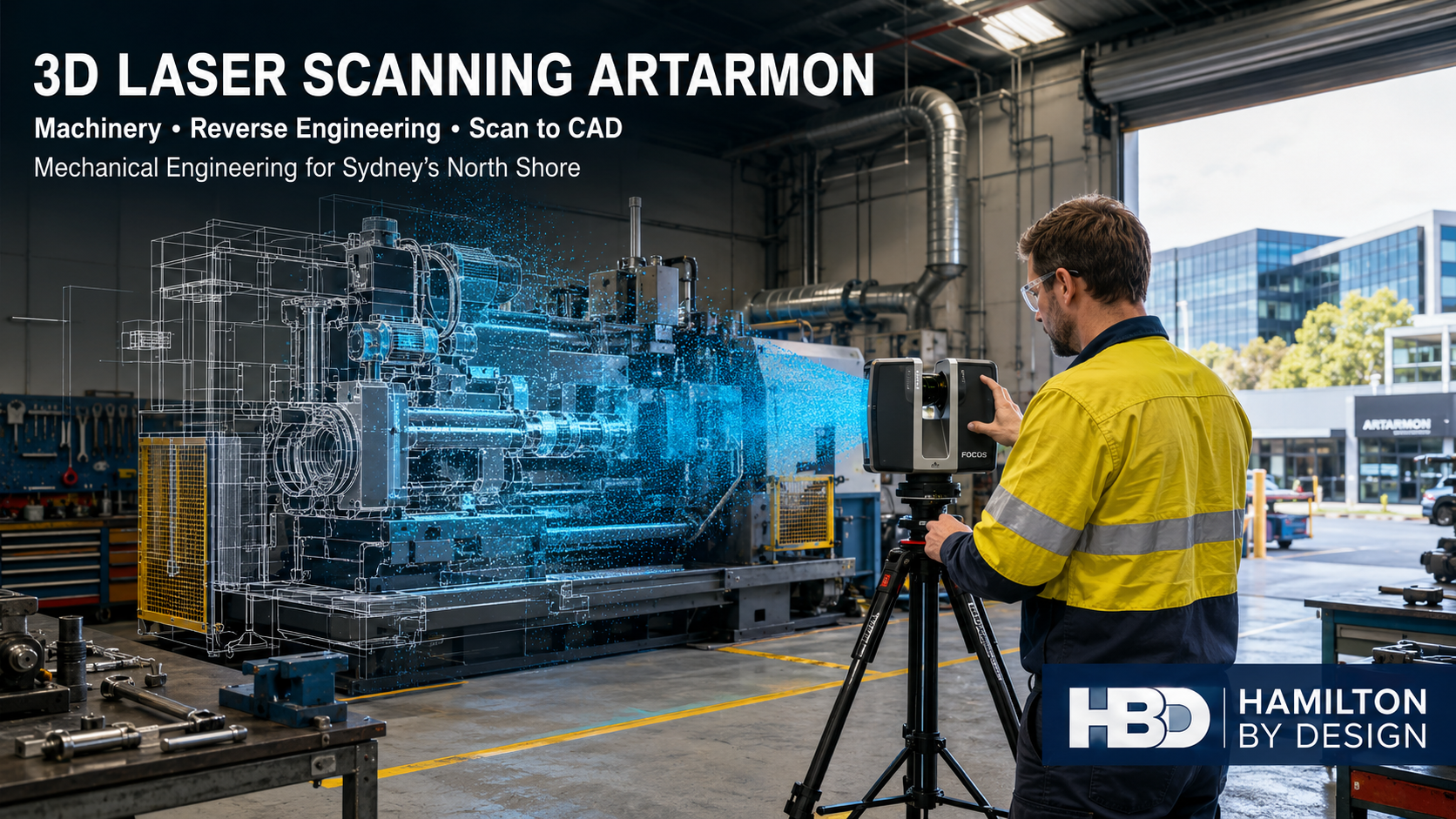
Hamilton By Design engineer using a 3D laser scanner to capture industrial machinery in an Artarmon workshop for reverse engineering and scan-to-CAD modelling.

Laser Scanning Artarmon: Machinery, Reverse Engineering and CAD Support

Blue 3D LiDAR scanner icon on a tripod with scanning waves

Artarmon is one of Sydneyโ€™s most strategically positioned urban industrial areas. Located close to the Sydney CBD, North Sydney, Chatswood and St Leonards, the precinct supports a diverse combination of specialised manufacturing, automotive servicing, machinery maintenance, broadcasting, construction materials, warehousing, logistics and technical businesses.

This industrial diversity creates a particular engineering challenge. Many Artarmon businesses operate from established facilities containing machinery, services and building elements that have been modified progressively over many years. Original drawings may be incomplete, existing layouts may not reflect actual site conditions, and replacement components may no longer be available from the original manufacturer.

Hamilton By Design provides engineering-led 3D laser scanning in Artarmon, supported by reverse engineering, mechanical design, point-cloud processing and CAD drafting. These services help businesses understand what currently exists, plan modifications with greater confidence and retain dependable engineering information for future maintenance and asset management.

Our wider 3D laser scanning services for Sydney combine site capture with practical mechanical and digital-engineering experience. This means the scan is not treated merely as a visual record. It becomes the foundation for drawings, equipment layouts, replacement parts, fabrication models, clearance assessments and safer brownfield modifications.

Supporting Artarmonโ€™s diverse industrial character

Artarmon is significantly different from a conventional outer-metropolitan industrial estate. It is a compact urban-services precinct with close connections to the Pacific Highway, Gore Hill Freeway, Lane Cove Tunnel and Sydneyโ€™s North Shore commercial and healthcare centres.

Its industrial character includes:

  • Automotive dealerships, service centres and repair workshops
  • Specialised manufacturing and engineering workshops
  • Concrete-production and construction-material facilities
  • Waste transfer and resource-recovery operations
  • Broadcasting, media and technical facilities
  • Warehouses and integrated officeโ€“distribution operations
  • Bulky-goods retail and trade supplies
  • Medical-equipment and hospital-support businesses
  • Machinery servicing and maintenance providers
  • Building-services and technical contractors

These businesses may operate very different equipment, but they often face similar engineering problems: restricted floor space, incomplete records, congested services, limited shutdown periods and the need to modify existing facilities without disrupting normal operations.

Hamilton By Designโ€™s broader Greater Sydney 3D scanning and digital-twin services are particularly applicable to these brownfield conditions. Accurate point-cloud data allows project teams to work from the physical facility rather than relying solely on drawings that may be outdated.

What is engineering-grade 3D laser scanning?

A terrestrial laser scanner captures large numbers of spatial measurements from the surfaces around it. Together, these measurements create a three-dimensional point cloud representing the visible geometry of machinery, buildings, structural elements, pipework, services and other physical assets.

Multiple scans can be registered into a common coordinate system to create a coordinated record of the required work area. Depending on the project scope, this data can then be supplied as a registered point cloud or converted into engineering deliverables.

Typical deliverables include:

  • E57, RCP, RCS or LAS point-cloud files
  • Existing facility and workshop layouts
  • Plans, elevations and sections
  • General arrangement drawings
  • SolidWorks machinery and equipment models
  • AutoCAD drawings
  • STEP, Parasolid and DXF files
  • Simplified coordination models
  • As-built drawings
  • Fabrication and manufacturing documentation
  • Clearance and clash-review models

Hamilton By Designโ€™s 3D laser scanning for engineering projects is intended to connect reality capture with a defined engineering purpose. Before scanning begins, the required deliverables, areas of interest, critical interfaces, coordinate requirements and appropriate level of detail should be established.

This is important because a visually impressive point cloud is not automatically an engineering model. The dataset must be captured, registered, checked and interpreted according to the decisions it is expected to support.

Machinery scanning in Artarmon

Machinery scanning is valuable when equipment must be modified, relocated, documented or integrated with new systems. Conventional hand measurement can be effective for simple components, but it becomes difficult when a machine contains complex geometry, inaccessible surfaces or numerous interfaces.

An engineering scan can capture:

  • Overall machine envelopes
  • Mounting points and baseplates
  • Connections and service interfaces
  • Guarding arrangements
  • Operator and maintenance access
  • Adjacent columns, walls and equipment
  • Platforms, stairs and walkways
  • Pipework and ducting near the machine
  • Overhead restrictions
  • Removal and installation routes

The scan can then be used to develop a simplified but accurate CAD representation. Rather than modelling every bolt or minor feature, the model can concentrate on the geometry required for the project.

For example, an automotive workshop may need to install a new vehicle lift, exhaust-extraction system or specialised test machine. A manufacturing business may need to extend an existing machine, add guarding or replace a feed arrangement. A technical facility may need new equipment installed around existing cable trays, cooling services and access routes.

Hamilton By Designโ€™s mechanical engineering services for plant and production problems can connect the captured geometry with practical modification design, equipment layouts and production-focused engineering decisions.

Reverse engineering obsolete components

Artarmonโ€™s machinery, automotive and specialist technical businesses may operate equipment for which original drawings, replacement parts or OEM support are no longer available. Replacing an entire machine because one component is obsolete can be financially inefficient and operationally disruptive.

Reverse engineering provides another option.

The process may include:

  1. Examining the component and understanding its function.
  2. Recording its relationship with the surrounding assembly.
  3. Scanning or measuring the existing geometry.
  4. Identifying worn, damaged or deliberately modified features.
  5. Reconstructing the intended geometry in CAD.
  6. Reviewing materials, tolerances and manufacturing methods.
  7. Producing a manufacturing model and controlled drawing.
  8. Supporting prototype manufacture, fit checking and testing.

This process requires engineering judgement. A worn component should not always be copied exactly because the scanned surface may represent damage rather than the original design. Critical dimensions, fits, sealing surfaces, load paths and operating conditions must be considered.

Hamilton By Designโ€™s approach to 3D laser scanning for engineering integrates physical measurement with CAD modelling and mechanical assessment. Where necessary, stress calculations or finite element analysis can be considered, subject to the information available and the significance of the component.

Reverse-engineered deliverables can include SolidWorks models, STEP files, Parasolid files, DXF profiles, machining drawings, fabrication drawings, assembly drawings and bills of materials.

Scan to CAD for brownfield modifications

Brownfield engineering begins with an existing asset or facility. This creates a different set of constraints from greenfield design because the new work must fit around what is already present.

Common brownfield risks include:

  • Existing drawings not matching the site
  • Previously undocumented modifications
  • Services crossing the proposed installation area
  • Insufficient maintenance access
  • Equipment that cannot pass through available openings
  • Structural or mechanical interfaces in unexpected locations
  • Fabrication based on assumed dimensions
  • New guarding conflicting with normal operations
  • Inadequate installation or lifting space

Hamilton By Designโ€™s CAD services in Sydney can convert point-cloud information into engineering-ready models and drawings. Depending on the project, this may include an existing-condition model, a proposed design model and a combined model used for spatial coordination.

The practical workflow is:

scan โ†’ register โ†’ model โ†’ engineer โ†’ detail โ†’ review โ†’ fabricate

This process reduces the dependence on repeated site measurement and provides designers, operators and fabricators with a shared spatial reference.

It does not remove the need for engineering review or installation planning. Instead, it improves the quality of information used in those activities.

Mechanical engineering for equipment modifications

Three-dimensional scanning establishes geometry, but geometry alone does not determine whether a modification is safe, functional or suitable for manufacture.

Hamilton By Design can support Artarmon clients with mechanical engineering for:

  • Machinery modifications
  • Equipment relocation
  • Machine bases and support frames
  • Guards, covers and barriers
  • Maintenance platforms and access
  • Brackets, frames and enclosures
  • Conveyor and material-handling modifications
  • Lifting attachments
  • Component replacement
  • Workshop and production layouts
  • Fabrication support
  • Load and clearance assessments
  • Preliminary FEA where appropriate

The companyโ€™s mechanical engineering services in Sydney can be delivered as a defined in-house package or integrated with the clientโ€™s existing project, maintenance or fabrication team.

Relevant Australian Standards depend on the equipment and the nature of the modification. They may include the AS/NZS 4024 machinery-safety series, AS ISO 12100 for machinery risk assessment, AS 1657 for fixed access, AS 3990 for mechanical equipment steelwork, AS 4991 for lifting devices and relevant parts of AS 1418 and AS 2550 for lifting equipment.

Where structural, electrical, fire or other specialist disciplines are involved, those aspects should be reviewed by appropriately qualified practitioners.

Mechanical drafting and manufacturing documentation

Good engineering information must be communicated clearly. A 3D model may assist visualisation, but workshops, fabricators, machine shops and site teams still require controlled documentation.

Hamilton By Design can prepare:

  • General arrangement drawings
  • Part and assembly drawings
  • Fabrication drawings
  • Machining drawings
  • Sheet-metal developments
  • Welded assembly details
  • Equipment and workshop layouts
  • Installation drawings
  • Exploded assembly views
  • Bills of materials
  • As-built drawings
  • DXF cutting profiles
  • STEP and Parasolid models
  • Revision-controlled drawing packages

The CAD and drafting services available in Sydney can also support drawing registers, revision tracking and issue statuses such as Issue for Review, Issue for Approval and Issue for Construction.

Where relevant, drawings can be prepared with reference to the AS 1100 technical-drawing series. Project-specific documentation should clearly communicate critical dimensions, tolerances, materials, finishes, weld requirements, interfaces and revision status.

Machinery safety and risk management

Modifying an existing machine may introduce new hazards even when the modification appears minor. A relocated guard may create a reach-through hazard. A new access platform may restrict emergency egress. Moving equipment may introduce a collision risk between forklifts and pedestrians.

Hamilton By Design can assist with engineering-focused risk reduction by documenting existing conditions and considering hazards such as:

  • Rotating and reciprocating components
  • Crushing and shearing points
  • Drawing-in and entanglement hazards
  • Ejected materials or failed components
  • Unexpected movement
  • Maintenance and isolation access
  • Falls from platforms or machinery
  • Vehicle and pedestrian interaction
  • Manual handling
  • Restricted emergency access

Three-dimensional scanning can make these risks easier to understand because proposed controls can be modelled in their actual physical context. Guards, barriers, access platforms and exclusion zones can be reviewed against the surrounding machinery before fabrication begins.

Risk management should follow a systematic process: identify hazards, assess credible consequences, apply the hierarchy of controls, document residual risks and review the effectiveness of the completed modification.

Logistics, warehousing and workshop layouts

Artarmonโ€™s proximity to major arterial roads supports warehousing, local distribution, trade supplies and automotive operations. However, its urban location also creates constrained sites, limited parking and frequent interaction between delivery vehicles, forklifts, workers and visitors.

Facility scanning can assist with:

  • Warehouse and workshop layouts
  • Loading and unloading zones
  • Storage-racking arrangements
  • Pedestrian and forklift separation
  • Bollards and impact protection
  • Equipment and production-flow planning
  • Material-handling systems
  • Truck access
  • Maintenance routes
  • Emergency access
  • Equipment relocation
  • Clearance beneath services and structures

Applicable requirements may include AS 4084 for steel storage racking, AS/NZS 4024.3610 for conveyors, AS 1657 for fixed access and relevant workplace traffic-management guidance.

A coordinated model allows safety, operations and engineering personnel to review a proposed layout together. This is particularly useful where additional equipment must be introduced without reducing access, storage capacity or operational safety.

From point cloud to digital asset record

The value of a scan does not necessarily end when the immediate project is completed. Properly managed data can become part of the organisationโ€™s engineering information system.

Hamilton By Design can retain:

  • Registered facility point clouds
  • Machine scans
  • CAD models
  • Workshop and warehouse layouts
  • Replacement-part models
  • Fabrication and machining drawings
  • Equipment interfaces
  • Revision histories
  • As-built project data

The principles discussed in digital twin creation and long-term asset management are relevant to Artarmon facilities that expect continuing modification, maintenance or tenancy change.

For larger facilities, selected information can also be incorporated into a Scan to BIM workflow. The appropriate approach depends on the intended use. A mechanical workshop may need fabrication-ready equipment geometry, while a commercial or technical facility may require a broader coordination or asset-management model.

Why use an engineering-led scanning service?

The most important question is not simply, โ€œHow accurately can the scanner measure?โ€ It is, โ€œWhat decision must be made using the resulting information?โ€

An engineering-led service considers:

  • Why the area is being scanned
  • Which interfaces are critical
  • What level of detail is necessary
  • Which output formats the client can use
  • Whether the model is for coordination, fabrication or asset records
  • How scanning uncertainty affects the design
  • Whether verification measurements are required
  • How data and revisions will be managed
  • What specialist reviews are needed

Hamilton By Design combines reality capture with mechanical engineering, reverse engineering and drafting. Its wider Sydney LiDAR scanning services support projects from initial site capture through to usable engineering documentation.

Examples of related applications can also be found through Hamilton By Designโ€™s engineering and 3D scanning case studies.

Frequently asked questions

What can be scanned in an Artarmon industrial facility?

Hamilton By Design can scan machinery, workshops, warehouses, plantrooms, equipment layouts, access platforms, structural interfaces, pipework and other visible facility elements. Smaller components may require a dedicated close-range scanning or measurement method.

Can machinery be scanned while a facility remains operational?

Often it can, provided the scan can be completed safely and moving people, vehicles or equipment do not prevent reliable data capture. Restricted or hazardous areas may require isolation, barricading, an escort or scanning during a planned quiet period.

How accurate is 3D laser scanning?

Accuracy depends on the scanner, range, environment, surface condition, scan geometry and registration method. Component reverse engineering and whole-facility capture may require different instruments and verification methods. Accuracy requirements should therefore be defined during scoping rather than assumed.

Can the point cloud be converted into SolidWorks or AutoCAD?

Yes. Required geometry can be converted into SolidWorks models, AutoCAD drawings, STEP files, Parasolid files, DXF profiles or simplified coordination models. The level of modelling should be selected according to the intended engineering use.

Can Hamilton By Design recreate an obsolete replacement part?

Potentially. The component must first be inspected to understand its function, damage, wear, interfaces, material and operating conditions. The objective is to reconstruct the intended functional geometry rather than blindly reproduce a worn surface.

Can scanning assist with machinery guarding?

Yes. Scanning can capture the machine, access routes, operating positions and surrounding obstructions. This information can support the design of guards, barriers and maintenance access with reference to the AS/NZS 4024 machinery-safety series.

Is a point cloud the same as a CAD model?

No. A point cloud is a measured collection of spatial points. A CAD model is interpreted geometry created for a defined purpose. Hamilton By Design can supply the registered point cloud, develop selected CAD geometry or provide both.

Can scanning help relocate machinery?

Yes. The existing machine and destination facility can be captured and compared. The resulting information can support equipment-envelope checks, access-route planning, service coordination, baseplate design and maintenance-clearance assessment.

What information can Hamilton By Design retain?

Subject to the agreed scope and data arrangements, Hamilton By Design can retain machine scans, facility point clouds, CAD models, layouts, replacement-part data and controlled drawings for future maintenance or modification work.

Does Hamilton By Design service areas near Artarmon?

Yes. Hamilton By Design supports projects across Artarmon, Chatswood, St Leonards, North Sydney and Greater Sydney. Related regional coverage is outlined on the Engineering and 3D Scanning Services NSW page, while Sydney construction applications are discussed in Building with Precision: 3D Scanning and LiDAR Modelling.

Discuss a 3D laser scanning project in Artarmon

Whether the requirement involves an undocumented machine, an obsolete component, a workshop modification or a complete facility layout, accurate existing-condition information provides a stronger basis for engineering decisions.

Hamilton By Design provides 3D laser scanning in Artarmon, reverse engineering, mechanical design, scan-to-CAD and engineering drafting for industrial, automotive, technical, warehousing and urban-service businesses across Sydneyโ€™s North Shore.

Our approach connects the physical asset with practical engineering deliverables:

scan โ†’ model โ†’ engineer โ†’ document โ†’ modify

Contact Hamilton By Design to discuss machinery scanning, reverse engineering, facility documentation or equipment modifications in Artarmon and the surrounding North Sydney region.


Hamilton By Design logo displayed on a blue tilted rectangle with a grey gradient background

Contact Us – Talk To Us

Name
Would you like us to arrange a phone consultation for you?
Address

Our clients:


Reverse Engineering Kirrawee | 3D Scanning & CAD

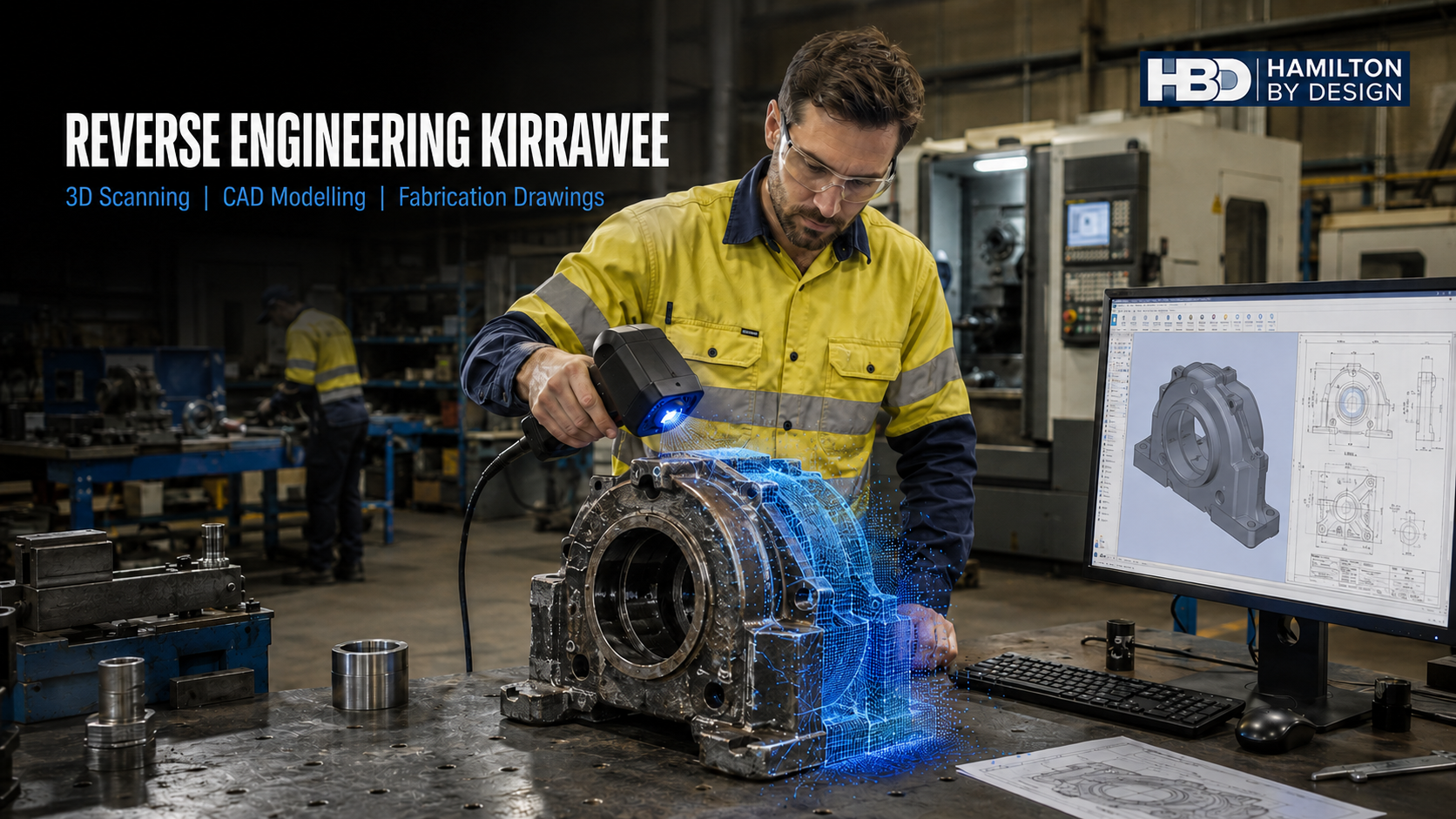
Mechanical engineer 3D scanning a machinery component for reverse engineering, CAD modelling and fabrication drawings in Kirrawee NSW.

Reverse Engineering Kirrawee: 3D Scanning, CAD Modelling and Fabrication Drawings for Local Industry

Blue mechanical engineering icon with gear and wrench

Kirrawee has an established industrial character shaped by fabrication workshops, specialist manufacturers, machinery businesses, automotive operations, construction suppliers and small industrial warehouses. Although the suburb is not a heavy-industrial centre, it contains a valuable concentration of businesses that manufacture, modify, repair and maintain physical equipment.

These operations regularly encounter a practical engineering problem: an important component, machine or fabricated assembly must be repaired or reproduced, but its original drawings are missing, incomplete or no longer accurate.

In other situations, drawings may exist but fail to reflect years of wear, modifications and workshop repairs. A replacement component manufactured directly from the old drawing may therefore reproduce the original geometry without fitting the equipment as it exists today.

Hamilton By Design provides reverse engineering in Kirrawee, combining detailed measurement, 3D scanning, mechanical engineering, CAD modelling and fabrication drawing services. This integrated process helps local manufacturers, workshop owners, fabricators, maintenance contractors and equipment operators convert physical assets into useful digital engineering information.

For larger machinery, workshop layouts and surrounding buildings, Hamilton By Design can provide 3D laser scanning in Kirrawee and Caringbah. For smaller parts and complex components, close-range scanning can capture detailed surface geometry before the information is converted into a practical CAD model.

The objective is not simply to produce a visually accurate model. It is to understand what the component does, identify its critical interfaces and create information that can support manufacturing, inspection, modification and future maintenance.

What Is Reverse Engineering?

Reverse engineering is the process of examining an existing physical product, component or assembly to determine its geometry, function, material characteristics and relationship with surrounding equipment.

In a manufacturing context, the process may be used to:

  • Reproduce an obsolete replacement part
  • Replace a component for which drawings are unavailable
  • Convert a physical item into a 3D CAD model
  • Document a machine that has been modified over time
  • Develop fabrication drawings from an existing assembly
  • Investigate premature wear or failure
  • Improve an existing component
  • Create a dimensional baseline for future inspections
  • Establish manufacturing information for a local supplier
  • Capture engineering knowledge before it is lost

A straightforward component may only require conventional measurement and a machining drawing. More complex objects may require a combination of detailed 3D scanning, physical inspection, material investigation, engineering calculations and manual verification of critical dimensions.

Hamilton By Designโ€™s broader approach to reverse engineering industrial equipment using 3D scanning is especially useful for castings, housings, curved fabrications, guards, ducts, machine frames and other components that cannot be described adequately using a small number of manual measurements.

Why Reverse Engineering Matters to Kirrawee Businesses

Kirraweeโ€™s industrial precinct includes CNC machining, metal fabrication, sheet-metal work, specialist tool manufacture, steel supply, equipment servicing and construction-related operations.

Companies in these sectors often work with machinery that has remained in service for many years. The equipment may still perform its intended function, but replacement parts can become increasingly difficult to obtain.

The original manufacturer may have:

  • Discontinued the machine
  • Withdrawn support for an older model
  • Lost or archived the relevant drawings
  • Changed ownership
  • Moved production overseas
  • Introduced an expensive minimum order
  • Imposed an unacceptable delivery period
  • Supplied a replacement that no longer matches the modified machine

These problems can create a disproportionate operational risk. A relatively small shaft, bracket, housing, guard, coupling or support may prevent an otherwise serviceable machine from operating.

Reverse engineering provides another pathway. Instead of treating the absence of OEM information as the end of the equipmentโ€™s useful life, the existing component can become the starting point for a new engineering record.

This approach can help Kirrawee businesses extend asset life, improve supply-chain independence and support local manufacturing. It can also create a controlled digital record so that the same investigative work does not have to be repeated the next time the component is required.

Kirraweeโ€™s Industrial and Manufacturing Profile

The broader Sutherlandโ€“Kirrawee area has strong connections to construction, trade supply, light manufacturing, automotive services and professional technical services. Kirrawee also benefits from access to the Princes Highway, Sydney Airport, Port Botany, southern Sydney and the Illawarra.

Local operations include:

  • CNC turning and milling
  • Component and tool manufacturing
  • Sheet-metal cutting and folding
  • Aluminium and stainless-steel fabrication
  • Structural and miscellaneous steel fabrication
  • Machinery servicing and modification
  • Automotive equipment and vehicle-related services
  • Building-product manufacture
  • Warehousing and trade supply
  • Small-batch production
  • Specialist installation work
  • Equipment repair and refurbishment

These businesses may both use and supply reverse-engineering services.

A machine shop, for example, may have the equipment needed to manufacture a replacement part but require a verified CAD model or machining drawing before production can begin. A fabricator may be capable of producing a platform, guard or support frame but need accurate information about the existing site. An asset owner may understand the operational problem but require engineering assistance to convert a damaged component into a suitable manufacturing package.

Hamilton By Design can help connect these stages through mechanical engineering consulting, scanning, modelling and documented engineering information.

The Five Major Problems Reverse Engineering Can Address

1. Missing or Unreliable Drawings

Many industrial assets do not have a complete drawing history. Original documents may have been lost during a company acquisition, workshop relocation or change of maintenance contractor.

Even where drawings remain available, they may not represent the current machine. Equipment is often altered during breakdowns, production changes and safety upgrades. Replacement components made from the original drawing may consequently fail to match the present arrangement.

Reverse engineering establishes a new dimensional record based on the actual asset.

2. Obsolete or Unavailable Components

A machine does not necessarily become technically unsuitable when its manufacturer stops supplying parts. In some circumstances, a locally manufactured replacement can extend its useful operating life.

This decision requires more than copying the visible shape. The componentโ€™s loading, interfaces, fits, material, manufacturing process, surface finish and likely failure mechanisms may all need consideration.

3. Complex Geometry

Castings, curved housings, fabricated transitions, ducts, guards and worn surfaces can be difficult to measure with rulers, tapes and callipers alone.

Three-dimensional scanning captures a dense surface record that can be inspected from different directions. Sections can be taken through the scan, symmetry can be evaluated, and complex geometry can be reconstructed in CAD.

4. Fabrication and Installation Errors

A new component may be dimensionally correct in isolation but still fail to fit the available space. Nearby steelwork, services, guards, floors and access restrictions can all affect installation.

Hamilton By Designโ€™s 3D scanning for fabrication in Sydney can capture both the component and its surrounding installation envelope. The proposed design can then be reviewed against existing conditions before material is cut.

5. Loss of Engineering Knowledge

In many workshops, essential knowledge is held by a small number of experienced employees. They may know which parts have been altered, which dimensions are critical and how an assembly must be installed.

If this knowledge is not documented, it can be lost when people retire, change roles or leave the business.

A controlled CAD model, drawing package and dimensional record help convert individual knowledge into an enduring business asset.

What Can Be Reverse Engineered?

Hamilton By Design can investigate a wide range of mechanical and fabricated items, including:

  • Machine components
  • Shafts and couplings
  • Bearing housings
  • Pump components
  • Brackets and mounting plates
  • Guards and access covers
  • Chutes, hoppers and transitions
  • Ductwork
  • Frames and skids
  • Equipment supports
  • Sheet-metal enclosures
  • Wear plates and liners
  • Pipework interfaces
  • Flanges and nozzles
  • Special-purpose tools
  • Fabricated assemblies
  • Obsolete replacement parts
  • Workshop machinery layouts

The appropriate capture method depends on the size, shape, material, surface condition and required manufacturing tolerance.

A complete workshop or large machine may be suited to terrestrial LiDAR scanning. A smaller casting or mechanical component may require close-range scanning. Precision features such as bearing seats, seal surfaces, threads and accurately machined bores should normally be verified using suitable contact-measurement or metrology equipment.

From Physical Component to CAD Model

A scan is not automatically a manufacturing model.

Raw scan data usually represents millions of measured surface points. It may include dirt, wear, corrosion, reflective noise, nearby equipment and areas hidden from the scanner. Engineering interpretation is needed to convert this information into deliberate design geometry.

The process generally includes the following stages.

Initial Scope Review

The first step is to understand why the component is being reverse engineered.

Questions may include:

  • Is an exact replacement required?
  • Has the original component worn or deformed?
  • What features connect with other equipment?
  • Which dimensions determine fit and function?
  • Is the proposed component safety-critical?
  • What loads does it experience?
  • What material was originally used?
  • Does the client want a model, drawing or complete engineering review?
  • Will one component or a production batch be manufactured?

This review determines the required level of detail and the most appropriate measurement method.

Physical Inspection and Data Capture

The component is photographed, measured and scanned as appropriate. Associated equipment may also need to be captured to establish mounting points, clearances and operating relationships.

Hamilton By Design provides 3D laser scanning for engineering projects where larger areas or complex existing conditions must be documented.

Point-Cloud or Mesh Processing

The scan data is aligned, checked and cleaned. Unwanted background information is removed, and the relevant surfaces are prepared for engineering interpretation.

The quality of this stage matters. Poorly aligned scan data can create false geometry and misleading measurements.

CAD Reconstruction

A practical CAD model is developed from the measured information. Depending on the component, this may involve:

  • Identifying axes and centre planes
  • Reconstructing nominal radii
  • Restoring symmetry
  • Establishing machined features
  • Defining plate thicknesses
  • Rebuilding sheet-metal geometry
  • Modelling weldments
  • Creating assemblies
  • Separating deliberate geometry from wear
  • Defining replaceable subcomponents

Hamilton By Design uses SolidWorks for engineering modelling and drafting where parametric, editable models are required.

Verification

Critical dimensions are checked against the physical component and its mating parts. Any assumptions, inaccessible areas or uncertain features should be documented.

Verification is particularly important where a part contains precision fits or performs a safety-related function.

Drawing and Manufacturing Information

The CAD model can then support:

  • Machining drawings
  • Fabrication drawings
  • Assembly drawings
  • General arrangements
  • DXF cutting profiles
  • Sheet-metal flat patterns
  • Bills of materials
  • Weld details
  • STEP or Parasolid files
  • Inspection dimensions
  • As-built records

Hamilton By Designโ€™s Australian design and drafting services can support the conversion of engineering geometry into controlled information suitable for review and manufacture.

Reproducing Worn or Damaged Parts

One of the most important reverse-engineering decisions is whether to copy the measured part exactly.

A worn component represents its present condition, not necessarily its original design. Copying every measured surface may reproduce defects such as:

  • Elongated holes
  • Uneven wear
  • Distorted plates
  • Bent shafts
  • Damaged sealing surfaces
  • Weld shrinkage
  • Corrosion loss
  • Previous repair material
  • Misalignment
  • Heat-related deformation

Engineering judgement is required to identify the likely nominal geometry.

Where possible, this may involve comparing opposite sides, evaluating symmetry, examining mating components, reviewing standard bearing or seal sizes and consulting maintenance personnel.

The final model should clearly distinguish measured information from reconstructed or assumed geometry. This traceability is important because it allows the client and manufacturer to understand the basis of the design.

Mechanical Engineering Support

Reverse engineering can lead directly into a wider mechanical engineering project.

Once the existing component has been documented, Hamilton By Design may assist with:

  • Functional assessment
  • Design improvement
  • Material review
  • Design for manufacture
  • Assembly and maintenance access
  • Component strengthening
  • Guarding integration
  • Load-path review
  • Connection detailing
  • Finite element analysis where appropriate
  • Prototype development
  • Fabrication support
  • Installation planning

Hamilton By Design provides broader mechanical engineering services in Sydney for manufacturing, industrial and equipment-related projects.

Where a modification affects a building or primary structural system, appropriately qualified structural engineering input may also be required. Hamilton By Design can provide mechanical design and drafting information and coordinate with the clientโ€™s structural engineer where necessary.

Mechanical Drafting and Fabrication Drawings

A sound model is only useful when the required information is communicated clearly.

Mechanical drafting can provide the bridge between the engineering investigation and the workshop. Depending on the project, the drawing package may include:

  • Overall and detail dimensions
  • Tolerances and fits
  • Material specifications
  • Weld symbols
  • Surface-finish requirements
  • Machining notes
  • Fastener information
  • Assembly relationships
  • Critical inspection points
  • Revision information
  • Drawing status
  • Parts lists
  • Cutting profiles

The AS 1100 technical-drawing series may provide the general foundation for drawing presentation. Other standards may apply depending on the component, manufacturing process and client requirements.

For welded steelwork, AS/NZS 1554.1 and AS/NZS 5131 may be relevant. Mechanical equipment steelwork may require consideration of AS 3990. Access platforms, walkways and stairs may involve AS 1657. The applicable standard should always be confirmed against the actual duty and project scope.

Machinery Safety and Guarding

Reverse engineering should not reproduce an unsafe condition without review.

Older machinery may contain exposed drives, belts, chains, shafts, cutting tools, pinch points or accessible moving parts. Existing guards may have been removed, damaged or modified to make maintenance easier.

Hamilton By Design can assist with:

  • Capturing existing machinery
  • Identifying guarding interfaces
  • Developing fixed-guard layouts
  • Designing removable covers
  • Reviewing maintenance access
  • Documenting doors and panels
  • Checking operator clearances
  • Preparing fabrication drawings
  • Recording residual design risks
  • Coordinating mechanical guarding with control-system specialists

The AS/NZS 4024 series is an important reference for machinery safety. SafeWork NSW guidance also emphasises suitable guarding, safe isolation, prevention of unexpected restart and consultation with the people who operate and maintain the machine.

Scanning can make guarding design more reliable because mounting points, surrounding equipment and access constraints are captured before the guard is fabricated.

However, a physical guard is only one part of machine safety. Electrical controls, interlocks, safety functions, isolation, operating procedures and worker training may require specialist input beyond the mechanical scope.

Supporting Workshop and Logistics Improvements

Reverse-engineering projects often reveal wider opportunities to improve a workshop or production area.

A scan can document not only the component but also:

  • Machine positions
  • Operator work areas
  • Maintenance clearances
  • Forklift routes
  • Pedestrian access
  • Loading areas
  • Storage locations
  • Overhead obstructions
  • Crane or hoist coverage
  • Equipment-removal paths
  • Service connections
  • Emergency access

Hamilton By Design can use this information to support machinery relocation, workshop layout development, lifting studies, fabricated transport frames and installation sequencing.

AS 4991 may apply to purpose-designed lifting devices. The AS 1418 and AS 2550 series may be relevant to cranes and their safe use. AS 1657 may apply to fixed access systems, while AS/NZS 4024 may apply where people interact with machinery.

The relevant requirements depend on the equipment, site and intended operation.

Risk Management and Design Documentation

Reverse engineering does not eliminate risk by itself. It provides better information from which risks can be identified, assessed and controlled.

Hamilton By Design can assist with engineering inputs to:

  • Design risk assessments
  • Plant hazard reviews
  • Machinery-modification assessments
  • Fabrication risk reviews
  • Installation planning
  • Maintenance-access reviews
  • Lifting assessments
  • Inspection and verification plans
  • Management-of-change records
  • Residual-risk registers

AS ISO 31000 provides general risk-management principles. Machinery projects may also require reference to the AS/NZS 4024 series, WHS legislation, applicable codes of practice and the clientโ€™s internal engineering standards.

The client or person conducting a business or undertaking retains responsibility for workplace risk management. Hamilton By Designโ€™s role is to contribute accurate site information, mechanical engineering analysis and documented design information within the agreed scope.

Engineering Data as a Long-Term Asset

A major benefit of reverse engineering is the creation of reusable data.

Depending on the project agreement, Hamilton By Design can retain or manage:

  • Machinery scans
  • Component scans
  • Registered point clouds
  • Native CAD models
  • STEP and Parasolid files
  • Replacement-part drawings
  • Fabrication drawings
  • Dimensional records
  • Revision histories
  • As-built documentation
  • Inspection information

This information can help the client avoid repeating site measurements and investigative work. It can also support future procurement, maintenance planning, design modifications and supplier changes.

The value is therefore greater than the immediate replacement component. The project can establish a controlled engineering record that supports the asset over the remainder of its operating life.

Why an Engineering-Led Approach Matters

Many technologies can produce a 3D image of an object. Fewer processes produce dependable engineering information.

Engineering-led reverse engineering considers:

  • What the component is intended to do
  • Which features are functionally important
  • Which surfaces are worn
  • Where tolerances are required
  • How the component will be manufactured
  • How it will be assembled
  • Whether it can be inspected
  • How it affects machinery safety
  • Whether the replacement will fit the existing equipment
  • What assumptions must be recorded

Hamilton By Design combines practical industry experience with scanning, CAD modelling, mechanical design and fabrication-aware drafting.

This approach supports the broader Hamilton By Design workflow of scan, model, engineer and upgrade.

Reverse Engineering Across Kirrawee and Southern Sydney

Hamilton By Design can support projects throughout Kirrawee, Sutherland, Caringbah, Taren Point, Miranda, Gymea, Heathcote, Menai, Cronulla and surrounding areas.

The reverse engineering services available in Taren Point are particularly relevant to businesses operating across the wider Sutherland Shire industrial market.

For organisations with facilities elsewhere in the metropolitan area, Hamilton By Design also provides engineering-led 3D scanning across Sydney and broader engineering and 3D scanning services throughout NSW.

Frequently Asked Questions

What is reverse engineering?

Reverse engineering is the process of examining an existing physical component, machine or assembly and converting the measured information into usable engineering data. The resulting information may include a CAD model, machining drawing, fabrication drawing, dimensional record or complete replacement-part package.

Can Hamilton By Design reverse engineer a component without drawings?

Yes. A physical component can be measured and scanned even when the original drawings are unavailable. The required process depends on its size, geometry, condition, function and manufacturing tolerance.

Can a worn component be used to create a new part?

Often, yes. However, the worn surface should not necessarily be copied directly. Hamilton By Design can evaluate symmetry, mating parts, standard component sizes and functional interfaces to estimate the intended nominal geometry. Important assumptions should be recorded for client review.

Is 3D scanning accurate enough to manufacture a replacement component?

It depends on the component and required tolerance. Scanning can be highly effective for overall geometry, curved surfaces, castings and fabricated assemblies. Precision features such as bearing seats, threads, shafts and seal surfaces should normally be checked with appropriate contact-measurement or metrology equipment.

What is the difference between a point cloud, mesh and CAD model?

A point cloud is a collection of measured points representing visible surfaces. A mesh joins surface information into interconnected triangles. A CAD model reconstructs deliberate engineering geometry such as planes, cylinders, holes, features and sheet-metal components. Manufacturing generally requires an appropriate CAD model or drawing rather than raw scan data alone.

Can Hamilton By Design produce fabrication drawings?

Yes. Depending on the agreed scope, Hamilton By Design can prepare general arrangements, fabrication drawings, machining drawings, assembly drawings, DXF profiles, sheet-metal flat patterns and bills of materials.

Can the model be supplied to a Kirrawee machine shop?

Yes. Deliverables may include STEP, Parasolid, DXF, DWG, SolidWorks and PDF files. The appropriate format should be agreed with the selected manufacturer before the drawing package is finalised.

Can reverse engineering improve the original component?

Yes. Once the original geometry and function are understood, the component may be reviewed for material changes, improved strength, reduced weight, easier manufacture, better maintenance access or improved safety. Any design change should be properly assessed rather than treated as a simple copy.

Can Hamilton By Design scan a complete workshop or machine?

Yes. Terrestrial 3D laser scanning can capture complete machinery, building geometry, nearby services, access routes and installation constraints. This is useful when a replacement assembly must fit within an existing operating area.

Can 3D scanning help prevent fabrication errors?

Yes. Proposed CAD geometry can be compared with the captured site condition before manufacture. This can identify clashes, incorrect connection positions, access restrictions and installation problems earlier in the project.

Can Hamilton By Design assist with machine guarding?

Hamilton By Design can assist with mechanical guard surveys, layouts, CAD models and fabrication drawings. The design may be reviewed against relevant parts of AS/NZS 4024. Electrical interlocks, safety-control systems and functional-safety validation may require appropriately qualified electrical or control-system specialists.

Which Australian Standards may apply?

Applicable standards depend on the component and project. Common references may include the AS 1100 technical-drawing series, AS/NZS 4024 for machinery safety, AS 3990 for mechanical equipment steelwork, AS 1657 for fixed access systems, AS 4991 for lifting devices, AS/NZS 1554.1 for welding and AS/NZS 5131 for structural steelwork fabrication and erection.

Can Hamilton By Design retain the scan and CAD information?

Data retention can be included in the project scope. Machinery scans, CAD files, dimensional records, drawings and revision histories can provide a valuable baseline for future maintenance, procurement and modification work.

Does reverse engineering breach the original manufacturerโ€™s intellectual property?

Reverse engineering can raise intellectual-property, licence or contractual issues, particularly where a component is protected by patents, copyright, confidentiality agreements or other restrictions. The asset owner should confirm that it has the legal right to reproduce or modify the component. Technical feasibility does not automatically establish a legal right to manufacture it.

How does a reverse-engineering project begin?

The project normally begins with photographs, available drawings, approximate component dimensions, the reason for replacement and a description of the equipmentโ€™s operation. Hamilton By Design can then recommend the appropriate inspection, scanning, modelling and engineering scope.

Discuss a Reverse Engineering Project in Kirrawee

A missing drawing or discontinued component does not always mean that an otherwise useful machine must be replaced.

Hamilton By Design can assist Kirrawee and Sutherland Shire businesses with machinery scanning, close-range component capture, CAD modelling, mechanical drafting, fabrication drawings and engineering review.

Whether the requirement involves one obsolete component, a modified machine, a new guard or a complete workshop upgrade, the process can begin by documenting what physically exists.

Visit Hamilton By Design to discuss reverse engineering, 3D scanning or mechanical drafting support for a Kirrawee project.


Hamilton By Design logo displayed on a blue tilted rectangle with a grey gradient background

Contact Us – Talk To Us

Name
Would you like us to arrange a phone consultation for you?
Address

Our clients:



Reverse Engineering Taren Point | 3D Scanning & CAD

Hamilton By Design engineer 3D scanning a marine pump for reverse engineering in Taren Point, with point-cloud and CAD model overlays.

Reverse Engineering Taren Point: 3D Scanning, Mechanical Design and Fabrication Drawings

Blue 3D LiDAR scanner icon on a tripod with scanning waves

Taren Point is one of the Sutherland Shireโ€™s most important industrial and employment areas. The precinct supports manufacturing, marine and automotive businesses, metal fabrication, specialist equipment suppliers, warehousing, building services and industrial maintenance. These operations depend on machinery and components that must remain serviceable, safe and capable of being modified as operating requirements change.

However, industrial assets do not always come with complete engineering records. Original drawings may be missing, manufacturers may no longer support older equipment, imported replacement parts may be unavailable, and years of maintenance can leave a machine significantly different from its original configuration. In marine environments, corrosion, wear, repairs and vessel modifications introduce further uncertainty.

Hamilton By Design provides reverse engineering in Taren Point to convert existing physical components and machinery into practical engineering information. This may include component scanning, dimensional measurement, 3D CAD modelling, mechanical design, fabrication drawings, inspection records and controlled digital asset information.

The service connects local Taren Point projects with Hamilton By Designโ€™s broader Reverse Engineering and 3D Scanning Sydney capability. The objective is not merely to reproduce the visible shape of a component. It is to understand how the component functions, how it interfaces with surrounding equipment and what information a manufacturer, fabricator or asset owner needs to achieve a reliable outcome.

Why reverse engineering matters in Taren Point

Reverse engineering is the structured process of examining an existing component, assembly or machine and developing new technical information from the physical asset. It is particularly valuable when the original design information is unavailable, unreliable or no longer representative of the equipment in service.

Taren Pointโ€™s combination of manufacturing, fabrication, marine servicing and industrial support businesses creates several common applications. A production facility may need to replace a discontinued roller, shaft, housing or guard. A marine operator may require a new bracket or equipment support that must fit an existing vessel. A fabricator may receive a worn physical sample but no drawing. An automotive workshop may need a jig, mounting plate or custom interface for a specialist installation.

In each case, measurement is only the beginning. The engineering process must distinguish the intended geometry from wear, deformation, corrosion, previous repairs and manufacturing variation. If a worn shaft is copied exactly, the new component may reproduce the defect rather than restore the correct fit. If a corroded marine bracket is duplicated without reconsidering material, drainage and loading, the underlying failure mechanism may remain.

This is where engineering-led reverse engineering differs from simple geometric copying. Hamilton By Design can combine physical evidence, operating requirements, material information and the surrounding installation to develop a more useful digital model and drawing package.

Connecting Taren Point projects with Sydney-wide capability

Taren Point is part of a larger Greater Sydney industrial network. Components may be scanned locally, modelled remotely, manufactured elsewhere in Sydney and returned to the site or vessel for installation. A successful engineering workflow must therefore transfer accurate information between the client, engineer, fabricator, machine shop and installer.

Hamilton By Designโ€™s 3D Scanning Sydney services support the capture of machinery, workshops, plant rooms, structures and surrounding installation conditions. Large-area scanning can be valuable when a component is only one part of a larger brownfield problem. For example, replacing a machine may also require confirmation of floor levels, access routes, service connections, maintenance clearances and structural interfaces.

The captured information can then be developed through Hamilton By Designโ€™s CAD Services Sydney capability. Depending on the project, deliverables may include SolidWorks parts and assemblies, general-arrangement drawings, fabrication drawings, machining drawings, installation details and simplified coordination models. This Sydney-wide capability gives Taren Point clients access to an integrated scan-to-CAD workflow rather than a disconnected collection of measurements.

For projects requiring a wider documentation package, Hamilton By Design also provides Engineering Design and Drafting Services. These services help convert site information and engineering decisions into drawings that can be reviewed, priced, manufactured, installed and retained for future use.

Typical reverse engineering applications

Obsolete and unavailable components

Industrial equipment frequently remains operational beyond the commercial life of its individual parts. Manufacturers can discontinue product lines, suppliers can leave the market and overseas lead times can make an otherwise modest component a major operational problem.

Hamilton By Design can inspect the available sample, identify critical interfaces and recreate the part as a controlled CAD model. The new design can then be reviewed for an appropriate manufacturing process such as machining, fabrication, laser cutting, folding, casting, additive manufacture or a combination of processes.

Marine equipment and vessel modifications

Marine work presents distinctive challenges. Equipment spaces may be confined, original vessel information may be incomplete, and components may have experienced corrosion, vibration, impact or repeated modifications. Scanning can assist with the capture of brackets, rails, housings, deck equipment, machinery supports, steering interfaces and complex surrounding geometry.

For commercial vessels, the applicable regulatory and technical requirements must be established at the beginning of the project. Machinery involving propulsion, fuel, fluid, steering or ancillary systems may fall within the National Standard for Commercial Vessels. The reverse engineering deliverable must therefore suit the componentโ€™s function and regulatory context, rather than treating every marine item as an isolated object.

Machinery modifications and production upgrades

Manufacturing businesses often need to modify existing machinery to increase capacity, improve access, introduce new products or reduce a safety risk. These projects can be difficult when the machine has no reliable model or when its actual position differs from old drawings.

Component scanning and site-based reality capture can establish the existing condition before new equipment is designed. This supports clearance checking, guarding development, maintenance-access reviews and coordination with structures or services. Where the design requires analytical verification, Hamilton By Designโ€™s FEA capabilities may assist with the assessment of stress, deflection or other defined loading conditions.

Fabrication drawings and manufacturing information

A scan or point cloud is not normally sufficient information for a fabricator. Manufacturing requires interpreted geometry, dimensions, materials, tolerances, weld information, surface finishes and revision status. Hamilton By Design can convert measured information into fabrication-ready documentation suited to the agreed scope.

Typical deliverables include:

  • 3D component and assembly models;
  • general-arrangement drawings;
  • machining and fabrication drawings;
  • cutting, folding and welded-assembly details;
  • bills of materials;
  • installation drawings;
  • inspection records; and
  • as-built revisions.

Drawing presentation may refer to AS 1100 technical-drawing principles, while steel design and fabrication may require consideration of AS 4100 and AS/NZS 1554.1. The exact standards depend on the component, material, loading, contractual requirements and intended application.

The reverse engineering process

An effective reverse engineering project begins with the operational problem, not the scanner. The required accuracy for a decorative cover is different from that required for a bearing fit, shaft, seal, bolted connection or aligned machinery interface.

Hamilton By Designโ€™s typical process can include the following stages:

  1. Define the requirement. Establish what is being replaced or modified, why the work is required and how the final information will be used.
  2. Review the existing asset. Inspect condition, access, materials, interfaces, wear, corrosion and previous modifications.
  3. Plan the measurement method. Select component scanning, laser scanning, conventional measurement or a combination of methods.
  4. Capture the geometry. Record the component and, where necessary, the surrounding machinery, structure or vessel installation.
  5. Develop the CAD model. Reconstruct appropriate nominal geometry and design intent rather than automatically copying every surface defect.
  6. Check critical interfaces. Confirm fits, datums, clearances, fasteners, alignment and installation constraints.
  7. Prepare drawings. Add manufacturing information, materials, tolerances, notes and revision control.
  8. Review and verify. Compare the model with the physical evidence and record assumptions or limitations.
  9. Support manufacture and installation. Respond to technical queries and update information where agreed.
  10. Retain controlled records. Store the agreed models, drawings and inspection information for future maintenance or modification.

The process can be adapted for a single component or a larger machinery installation. It can also connect with Hamilton By Designโ€™s broader structural engineering services where equipment supports, platforms or structural interfaces form part of the project.

Five common problems and how they can be addressed

1. Missing or inaccurate drawings

Old drawings may not reflect modifications made during installation or maintenance. Physical verification helps establish the actual condition before new work begins.

2. Worn, damaged or corroded samples

A damaged sample cannot always be copied directly. Engineering interpretation is needed to identify likely original geometry, appropriate tolerances and the cause of deterioration.

3. Difficult-to-measure geometry

Curved marine components, castings, moulded parts and confined machinery interfaces can be inefficient to capture using manual methods alone. Scanning can collect dense geometric information, while targeted measurements establish critical features.

4. New equipment that does not fit

Brownfield installations contain real-world deviations, obstructions and access limitations. Capturing surrounding conditions supports digital fit checking and reduces avoidable site rework.

5. Uncontrolled engineering information

Uncontrolled files can result in the wrong component being manufactured or an obsolete drawing being used. Drawing registers, approval status and revision control help maintain a traceable technical record.

Mechanical safety and risk management

Reverse engineering an operating machine is not only a dimensional exercise. A replacement or modification can alter guarding, access, stored energy, maintenance tasks, load paths or operator interaction. These changes should be reviewed through a structured safety-in-design and risk-management process.

Hamilton By Design can assist with hazard identification, machinery layouts, guarding concepts, maintenance access, isolation-point layouts and design risk registers. The AS/NZS 4024 machinery-safety series may be relevant to guarding and plant design. AS 1657 may apply to fixed platforms, walkways, stairs and ladders, while AS ISO 31000 provides broader risk-management principles.

The standards applicable to a particular project must be confirmed according to the plant, materials, intended use, legislation and client requirements. Engineering assistance does not remove the asset ownerโ€™s work health and safety obligations or replace specialist inspection, regulatory approval or certification where these are required.

Engineering data as a long-term asset

One of the greatest benefits of reverse engineering is the creation of information that can support future work. Subject to the agreed project and data-management arrangements, Hamilton By Design can retain component models, machinery scans, CAD assemblies, fabrication drawings and inspection records.

This information can help a client order another part, review a later modification, investigate a failure or brief a different manufacturer without beginning again from an undocumented physical sample. Controlled data can be particularly valuable to a small manufacturing or marine business where much of the asset knowledge would otherwise remain with one employee or contractor.

Hamilton By Design has provided practical engineering and digital-design support since 2001. More information about its approach and experience is available on the About Hamilton By Design page.

Frequently asked questions

What is reverse engineering?

Reverse engineering is the process of examining an existing physical component or machine and developing new technical information from it. The output may include measurements, a 3D CAD model, engineering analysis, fabrication drawings or inspection records.

Can Hamilton By Design reverse engineer a component without an original drawing?

Yes. Missing drawings are a common reason for reverse engineering. The available component can be measured or scanned, although its condition and the required accuracy must be assessed before the appropriate deliverables are agreed.

Is 3D scanning accurate enough for manufacturing?

It can be, provided the selected scanner, capture method and verification process suit the component and tolerances. Critical bores, threads, bearing fits and machined interfaces may require conventional metrology in addition to scanning.

Can a worn or broken component be reverse engineered?

Often, yes. The model should not automatically reproduce the damage. Adjacent parts, symmetry, remaining unworn surfaces, standard fits and the componentโ€™s function may help reconstruct its likely design intent.

Do you provide 3D scanning in Taren Point and the Sutherland Shire?

Hamilton By Design supports Taren Point through its broader Sydney scanning and engineering capability. The scope can include an individual component, industrial machinery, a workshop area or surrounding installation conditions.

Can you prepare fabrication and machining drawings?

Yes. Depending on the scope, Hamilton By Design can prepare general arrangements, machining drawings, welded-fabrication drawings, assemblies, bills of materials and installation details.

Can you assist with marine equipment?

Yes. Potential applications include equipment supports, brackets, rails, housings, machinery interfaces and vessel-refit geometry. Commercial-vessel requirements and any necessary survey or regulatory involvement must be established for the specific project.

Can the design be modified rather than copied exactly?

Yes. Once the existing geometry and function are understood, the component can potentially be adapted for different materials, manufacturing processes, interfaces or operational requirements. Any change should be assessed against the applicable loads, risks and standards.

What information should a client provide?

Useful information includes photographs, dimensions, operating conditions, material details, failure history, mating components, old drawings, required quantity, manufacturing preference and the reason the component is being replaced or modified.

Can Hamilton By Design retain the project data?

Subject to the agreed commercial, confidentiality and data-management arrangements, relevant scans, models, assemblies, drawings and inspection information can be retained as controlled engineering records.

Reverse engineering support for Taren Point

For Taren Point manufacturers, marine businesses, fabricators and industrial service providers, reverse engineering offers a practical route from an undocumented physical asset to reusable engineering information. It can reduce uncertainty, support local manufacture, improve installation planning and create a record that remains valuable after the immediate repair or modification is complete.

Hamilton By Design combines component scanning, Sydney-wide reality capture, mechanical engineering, CAD modelling and fabrication documentation to support this process. Whether the requirement involves one obsolete part or a coordinated machinery upgrade, the work begins by defining the operational problem, the required accuracy and the final engineering deliverables.

To understand the experience behind these services before discussing a reverse engineering, 3D scanning, mechanical design or fabrication-drawing project in Taren Point or elsewhere in Sydney, learn more about Hamilton By Design.

Applicable standards, verification requirements and regulatory approvals must be confirmed for each project according to the component, equipment, vessel, material, loading, contract and intended use.


Hamilton By Design logo displayed on a blue tilted rectangle with a grey gradient background

Contact Us – Talk To Us

Name
Would you like us to arrange a phone consultation for you?
Address

Our clients:
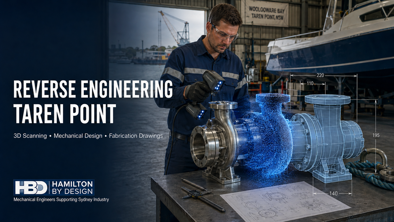


Reverse Engineering Peakhurst | Component Scanning & CAD

Reverse engineering in Peakhurst showing an engineer 3D scanning a bearing housing to create a CAD model and fabrication drawings.

Reverse Engineering Peakhurst: Component Scanning, CAD Modelling and Fabrication Drawings

Blue 3D LiDAR scanner icon on a tripod with scanning waves

Peakhurst is an established industrial area in southern Sydney with a practical concentration of precision manufacturing, metalwork, machinery services, commercial joinery, industrial equipment, fabrication and specialist workshops. These activities depend on accurate dimensions, controlled technical information and machinery that can be maintained or modified without unnecessary production delays.

However, many industrial businesses operate equipment for which the original engineering information is incomplete, outdated or no longer available. A machine may have been modified repeatedly during its operating life. A component may be worn, damaged or commercially obsolete. An overseas manufacturer may no longer support the equipment, while a replacement part may have an unacceptable cost or lead time.

Hamilton By Design provides reverse engineering in Peakhurst to help businesses convert existing components and machinery into practical engineering information. This may involve component scanning, physical measurement, 3D CAD modelling, mechanical drafting, fabrication drawings, machinery modifications and the controlled retention of project records.

The objective is not simply to produce a digital copy of an object. Engineering-led reverse engineering considers what the component does, how it interacts with adjoining parts, how it may have worn and what information a manufacturer needs to reproduce or improve it successfully.

Why Peakhurst Is Well Suited to Reverse Engineering

Peakhurstโ€™s industrial character includes precision CNC machining, CAD/CAM operations, welding, steel fabrication, dimensional inspection, prototyping and joinery manufacturing. This creates a useful relationship between businesses that need engineering information and workshops capable of manufacturing from models and drawings.

Publicly described local capabilities include multi-axis machining, coordinate measurement, rapid prototyping, steelwork, welding and commercial joinery. These operations demonstrate that Peakhurst is not simply a warehouse area. It contains technically capable manufacturers and workshops that rely on accurate digital models and controlled production information.

Reverse engineering can bridge the gap between an existing physical asset and these manufacturing capabilities. Hamilton By Designโ€™s reverse engineering and Scan-to-CAD studies provide a structured method for capturing existing geometry and converting it into engineering models and drawings.

This can support local manufacture, equipment repair, product improvement, machinery modification or the creation of a reliable asset record.

What Is Reverse Engineering?

Reverse engineering is the systematic process of examining an existing component, machine or assembly to recreate the technical information required to understand, reproduce, modify or replace it.

The starting point may be:

  • An existing component without a drawing
  • A worn or damaged machine part
  • An obsolete replacement item
  • A fabricated frame or assembly
  • A machine that has been modified on site
  • An imported system with limited documentation
  • A sample provided to a machining or fabrication workshop
  • An incomplete or unreliable drawing set

The required outcome might be a 3D CAD part, mechanical assembly, manufacturing drawing, fabrication package, machinery layout or dimensional comparison report.

Hamilton By Designโ€™s work on reverse engineering industrial equipment using 3D scanning combines captured geometry with engineering judgement. This distinction matters because scan data alone does not define the original design intent.

Five Common Problems Facing Peakhurst Businesses

1. Missing or outdated machinery drawings

Industrial machinery is frequently modified during maintenance, breakdown repairs or production upgrades. New brackets may be added, guards replaced and components altered without the engineering drawings being updated.

Over time, the available documentation becomes progressively less reliable. A future modification may then be designed around a drawing that no longer represents the physical machine.

Scanning and measuring the installed asset provides a new as-built reference. The captured data can be used to produce a controlled CAD model and updated drawings reflecting the equipmentโ€™s current arrangement.

2. Obsolete replacement components

A replacement component may no longer be commercially available. The original manufacturer may have ceased trading, stopped supporting the machine or relocated its spare-parts operation overseas.

Reverse engineering can establish the geometry required to investigate repair or local manufacture. This may reduce dependence on unsupported equipment suppliers and provide the asset owner with a reusable engineering record.

However, geometry is only one part of the problem. A scan cannot independently determine:

  • Material grade
  • Heat treatment
  • Surface hardness
  • Internal geometry
  • Original design loads
  • Surface finish
  • Manufacturing tolerance
  • Fatigue history
  • Allowance for wear or corrosion

These factors must be established through inspection, research, testing, calculations and engineering judgement before a replacement part is released for production.

3. Unclear manufacturing requirements

A highly detailed mesh may look impressive on a computer screen but still be unsuitable for manufacturing. A machine shop needs more than an external surface.

Manufacturing information may need to define:

  • Nominal dimensions
  • Fits and clearances
  • Geometric tolerances
  • Threads and fasteners
  • Bearing and seal seats
  • Materials
  • Surface finishes
  • Weld requirements
  • Heat treatment
  • Inspection dimensions
  • Assembly relationships

Hamilton By Design provides 3D CAD modelling in Sydney to convert captured geometry into practical parts and assemblies. The aim is to create a structured engineering model rather than leaving the client with an uncontrolled mesh.

4. Machinery modification and installation risk

A replacement part may fit the component in isolation but interfere with the complete machine. Similarly, a new guard, frame or support may clash with electrical services, access routes, adjoining equipment or maintenance requirements.

Scanning the component together with the surrounding machinery helps identify these physical interfaces. For broader modifications, 3D scanning services in Sydney can capture the machine, workshop and nearby infrastructure as a coordinated existing-condition record.

This can reduce the risk of discovering errors during installation, when modification is often most expensive and disruptive.

5. Fragmented engineering data

Machinery records may be spread across old drawing cabinets, individual computers, maintenance systems and external contractors. Files may use inconsistent naming conventions or contain no clear revision history.

A reverse engineering project provides an opportunity to create a controlled asset record containing the approved component geometry, CAD models, drawings, inspection information, photographs, assumptions and revision status.

A Practical Reverse Engineering Workflow

Step 1: Define the purpose

The first question is not โ€œWhich scanner should be used?โ€ It is โ€œWhat engineering decision must the information support?โ€

A model created only for visualisation will have different requirements from a component intended for precision CNC machining. The project scope should define:

  • The component or machine being investigated
  • Its operating function
  • The reason for reverse engineering
  • Critical interfaces
  • Required accuracy
  • Deliverable formats
  • Proposed manufacturing process
  • Required design or safety reviews

This early definition determines the appropriate measurement tools and level of modelling detail.

Step 2: Review existing information

Existing drawings, manuals, photographs, samples and maintenance records should be collected. Even an outdated drawing may contain useful information about nominal dimensions, materials or the original design intent.

Operators and maintenance personnel can also provide valuable evidence. They may know where the equipment regularly fails, which components have been altered and what access problems affect servicing.

Step 3: Inspect the component or machine

The physical asset should be inspected before capture. The review should identify:

  • Wear and deformation
  • Corrosion
  • Missing features
  • Repairs and weld build-up
  • Inaccessible surfaces
  • Moving interfaces
  • Critical datums
  • Mating components
  • Areas requiring detailed measurement

A worn component should not necessarily be recreated at its measured worn size. Bearings, seals, shafts, housings and standard fits may help establish the intended nominal dimensions.

Step 4: Select the correct measurement tools

Different capture tools suit different applications.

A handheld laser or structured-light scanner can be effective for castings, moulded parts, guards, housings and complex surfaces. Terrestrial LiDAR is better suited to complete machines, production areas and workshop layouts.

Critical features may also require calipers, micrometers, bore gauges, thread gauges, height gauges or specialist coordinate-measuring equipment.

Hamilton By Designโ€™s 3D laser scanning and CAD modelling services integrate real-world capture with engineering modelling. The selected method should always reflect the required tolerance and intended use of the data.

Step 5: Process and verify the data

Captured scans must be processed, aligned and checked. Temporary objects, reflections and inaccessible areas may create incomplete or misleading geometry.

Reference measurements should be used to verify scale and alignment. For precision components, the expected measurement uncertainty must be compared with the required manufacturing tolerance.

A scan that is suitable for documenting a machine frame may not be sufficiently accurate for a bearing seat. Additional metrology may be required where tight fits or critical inspection requirements are involved.

Step 6: Create the engineering model

The point cloud or mesh becomes a reference for building the CAD model. Depending on the project, the model may contain:

  • Machined features
  • Sheet-metal parts
  • Weldments
  • Shafts and rollers
  • Brackets
  • Housings
  • Guards
  • Machine frames
  • Mechanical assemblies
  • Installation interfaces

Hamilton By Designโ€™s SolidWorks drafting services can support parametric component models, assemblies and manufacturing documentation.

A parametric model is generally more useful than an uncontrolled scan mesh because features can be reviewed, dimensioned and modified as the design develops.

Step 7: Review function and manufacture

The reconstructed model should be reviewed against the componentโ€™s function and proposed manufacturing process.

This may include consideration of:

  • Material selection
  • Fits and tolerances
  • Load paths
  • Wear surfaces
  • Alignment
  • Fasteners
  • Welded connections
  • Tool access
  • Machining sequence
  • Assembly and disassembly
  • Inspection requirements
  • Maintenance access

Where loads, materials and boundary conditions are sufficiently defined, engineering calculations or finite element analysis may be used to assess a design or compare alternatives.

Step 8: Prepare drawings

A complete drawing communicates the information that cannot be inferred reliably from the 3D model.

Hamilton By Designโ€™s Australian design and drafting services can provide:

  • Component drawings
  • Manufacturing drawings
  • Fabrication drawings
  • General arrangements
  • Assembly drawings
  • Exploded views
  • Bills of materials
  • Sheet-metal flat patterns
  • DXF cutting profiles
  • Installation drawings
  • Controlled PDF drawing sets
  • Agreed CAD exchange formats

Drawings should use appropriate dimensions, tolerances, materials, weld symbols, finishes, notes and revision controls.

Machinery Modifications in Peakhurst

Reverse engineering is not limited to copying parts. It can also support machinery upgrades and modifications.

Hamilton By Designโ€™s mechanical engineering services in Sydney may assist with:

  • Modified machine frames
  • Replacement brackets and supports
  • Conveyor changes
  • Equipment interfaces
  • Guards and enclosures
  • Platforms and maintenance access
  • Chutes and transfer arrangements
  • Workshop equipment layouts
  • Installation planning

The existing equipment can be scanned before the modification is designed. The proposed design can then be overlaid against the captured geometry to assess clearances and potential clashes.

Mechanical Drafting and Australian Standards

The relevant Australian Standards depend on the machine, component, material and application. Standards should be selected for the actual project rather than applied as a generic list.

Potential references include:

  • AS 1100 series for technical drawing conventions
  • AS/NZS 4024 series for machinery safety
  • AS/NZS 4024.3610 for conveyors
  • AS 1657 for fixed platforms, walkways, stairs and ladders
  • AS 4100 for steel structures
  • AS/NZS 1554 for structural steel welding
  • AS 4991 for lifting devices
  • AS 4084 for steel storage racking
  • AS ISO 31000 for risk-management principles
  • AS/NZS 3000 where electrical installation requirements are relevant

Pressure equipment may also require consideration of AS/NZS 1200, AS 1210 or AS 4041, depending on the asset and scope.

Producing a drawing with reference to an Australian Standard does not automatically certify the machine, structure or component. Design verification, certification and statutory approval must be specifically included in the scope and undertaken by appropriately qualified or licensed people.

Machinery Safety and Risk Management

Machinery modification can introduce new hazards or alter existing controls. Changes to guards, frames, access points or operating sequences should therefore be reviewed systematically.

Common workshop and machinery hazards include:

  • Rotating shafts and couplings
  • Conveyor nip points
  • Crushing and shearing zones
  • Entanglement
  • Unexpected movement
  • Stored pneumatic, hydraulic or mechanical energy
  • Ejected components
  • Hot surfaces
  • Inadequate maintenance access
  • Unsafe platforms and stairs
  • Interaction between pedestrians and mobile equipment

Hamilton By Design provides machine guarding design and engineering for industrial machinery and materials-handling systems. Assistance may include machinery capture, hazard reviews, guard concepts, access arrangements and fabrication drawings.

Risk controls should follow the hierarchy of controls. Hazards should be eliminated where reasonably practicable before relying on isolation, engineering controls, administrative procedures or personal protective equipment.

Supporting Logistics and Workshop Layouts

Peakhurst also supports warehousing, distribution and workshop operations where equipment layout influences productivity and safety.

Engineering and scanning services can assist with:

  • Workshop machinery layouts
  • Equipment relocation
  • Conveyor arrangements
  • Racking interfaces
  • Loading and unloading zones
  • Forklift and pedestrian separation
  • Maintenance clearances
  • Palletising equipment
  • Special-purpose lifting devices
  • Installation drawings
  • Clash detection
  • As-built documentation

These projects may involve AS 4084 for steel storage racking, AS/NZS 4024.3610 for conveyors, AS 1657 for fixed access systems and AS 4991 for lifting devices.

Retaining Component and Machinery Data

The lasting value of reverse engineering depends on how the information is retained.

Subject to the agreed project arrangements, Hamilton By Design can retain:

  • Component geometry
  • Point clouds and meshes
  • CAD parts and assemblies
  • Machinery records
  • Manufacturing and fabrication drawings
  • Dimensional inspection information
  • Photographs
  • Design assumptions
  • Drawing revisions
  • Superseded files

This information can support later repairs, replacement parts, safety improvements and machinery modifications without repeating the complete capture process.

Frequently Asked Questions

What types of components can be reverse engineered?

Potential components include shafts, rollers, brackets, housings, guards, fabricated frames, machine parts, castings, sheet-metal items and mechanical assemblies. Suitability depends on the componentโ€™s size, accessibility, condition and required manufacturing accuracy.

Can a component be manufactured directly from a scan?

Not usually without further engineering work. A scan provides accessible surface geometry, but manufacturing may also require nominal dimensions, tolerances, materials, heat treatment, surface finish and inspection requirements.

What if the component is worn or damaged?

The measured geometry can be assessed against mating components, bearings, seals, standard sizes and any available historical information. The intended nominal geometry may then be reconstructed rather than simply copying the wear.

Which scanner is best for component reverse engineering?

The appropriate scanner depends on component size, geometry, surface condition and required tolerance. Handheld scanners are often suitable for detailed components, while terrestrial LiDAR is generally better for complete machinery and workshop layouts.

Can Hamilton By Design prepare SolidWorks models?

Yes. Scan and measurement data can be used to develop SolidWorks parts, assemblies, sheet-metal models and weldments. STEP, DWG, DXF, PDF and other agreed deliverables may also be provided.

Can the drawings be used by a local Peakhurst machine shop?

The drawings can be prepared to communicate the agreed manufacturing requirements. The selected machine shop should review the package and confirm its process, tooling, tolerances, inspection methods and production capability before manufacture.

Can reverse engineering improve an existing component?

Yes. The existing component can be used as the starting point for reviewing wear, access, manufacturability or recurring failure. Any design change should be assessed against the componentโ€™s function, loads, interfaces and safety requirements.

Can machinery and the surrounding workshop be scanned together?

Yes. Capturing the wider area can help assess equipment access, clearances, structural interfaces and potential clashes during machinery modification or relocation.

Can reverse engineering assist with machinery safety?

Yes. Machinery capture can help identify exposed moving parts, unsafe access and inadequate guarding. Hamilton By Design can develop guarding and modification concepts, subject to the agreed engineering and verification scope.

How long does a reverse engineering project take?

The timeframe depends on component complexity, site access, required accuracy, available historical information and the level of manufacturing documentation required. A simple component may be completed relatively quickly, while a complete machine may require staged capture, modelling and review.

Can Hamilton By Design retain the engineering files?

Yes, subject to the agreed commercial, confidentiality and data-management arrangements. Retention can include component geometry, CAD models, drawings and dimensional records.

Engineering Support for Peakhurst Manufacturers

Reverse engineering provides Peakhurst manufacturers, fabricators and workshop operators with a structured way to recover missing engineering information.

When component scanning is combined with physical measurement, CAD modelling, mechanical design and controlled drafting, an existing asset can become a practical engineering resource. The resulting information may support component replacement, machinery modification, local manufacture, safety improvements or future maintenance.

Hamilton By Design provides reverse engineering, component scanning, mechanical drafting, fabrication drawings and machinery-modification support for businesses in Peakhurst and across Sydney.

Whether the requirement involves a single machine part or a complete workshop installation, the process begins by defining the operational problem, the required accuracy and the engineering deliverables needed to solve it.


Hamilton By Design logo displayed on a blue tilted rectangle with a grey gradient background

Contact Us – Talk To Us

Name
Would you like us to arrange a phone consultation for you?
Address

Our clients:
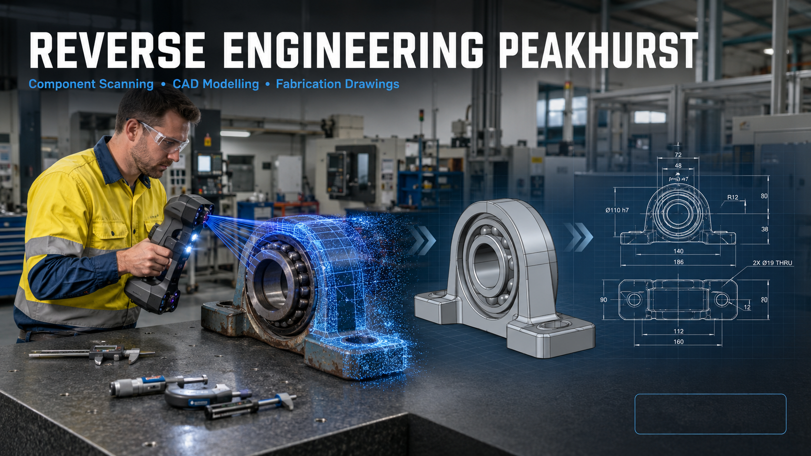


Reverse Engineering Kingsgrove | 3D Scanning & CAD

Reverse engineering in Kingsgrove showing an engineer 3D scanning industrial machinery to create a CAD model and fabrication drawings.

Reverse Engineering Kingsgrove: Turning Existing Machinery into Accurate Engineering Data

Blue 3D LiDAR scanner icon on a tripod with scanning waves

Kingsgrove is one of southern Sydneyโ€™s established industrial areas. Its combination of food production, packaging machinery, electrical products, automation, plastics, rubber products, fabrication and warehousing creates an ongoing need for practical mechanical engineering support.

Many businesses in the area rely on machinery that has operated for years or even decades. During that time, equipment may have been modified, relocated, repaired or upgraded without the original engineering drawings being revised. Other machines may have been imported without complete documentation, while replacement components may no longer be commercially available.

Hamilton By Design provides reverse engineering in Kingsgrove to help manufacturers, machinery suppliers, fabricators and warehouse operators recover this missing engineering information. Through machinery scanning, physical measurement, CAD modelling and engineering assessment, an existing component or machine can be converted into a controlled digital model and a practical set of manufacturing or fabrication drawings.

The objective is not simply to reproduce an objectโ€™s external shape. Effective reverse engineering must establish how the component functions, how it connects to surrounding equipment, what loads it may experience and what manufacturing requirements must be communicated.

What Is Reverse Engineering?

Reverse engineering is the structured process of examining an existing component, machine or system to recreate the engineering information required to understand, reproduce, modify or replace it.

The starting point may be:

  • An existing machine without drawings
  • A worn or damaged component
  • An obsolete replacement part
  • An imported machine with limited documentation
  • A fabricated assembly that has been modified on site
  • A production line that no longer matches its original layout
  • A component sample supplied to a machine shop
  • An incomplete or inaccurate drawing set

Depending on the project, the resulting information may include a 3D CAD model, manufacturing drawing, fabrication drawing, assembly model, general arrangement, factory layout or documented as-built record.

Hamilton By Design combines physical measurement with reverse engineering and Scan-to-CAD studies. This engineering-led approach allows captured geometry to be developed into information that designers, manufacturers, fabricators and maintenance teams can use.

Why Reverse Engineering Is Important in Kingsgrove

Kingsgroveโ€™s industrial businesses often operate in established buildings where production equipment, building services, storage systems and access routes must share a limited amount of space.

A new machine may need to fit between existing columns, conveyors and services. A replacement component may have to connect to equipment manufactured overseas many years ago. A new guard may need to provide safe access without interfering with production or maintenance activities.

Traditional tape measurements and site sketches remain useful, but they can be inefficient when equipment contains complex curves, numerous interfaces or inaccessible features. A small dimensional error can lead to a component that cannot be installed or an assembly that requires modification during a shutdown.

Reverse engineering industrial equipment using 3D scanning provides a more complete record of the existing asset. When combined with critical manual measurements and appropriate engineering checks, scanning can reduce uncertainty and provide a reliable basis for design.

Common Reverse Engineering Problems

Missing or outdated drawings

Machinery is frequently altered during maintenance, repairs or production upgrades. If the drawings are not updated, the documented design gradually becomes different from the physical machine.

Scanning allows the current arrangement to be captured so that new models and drawings represent the actual installed condition rather than an earlier design.

Obsolete replacement parts

Manufacturers may discontinue a component, cease trading or no longer support an older machine. Imported replacement parts may also involve long lead times and significant freight costs.

Reverse engineering can help recreate the dimensional information needed to investigate local manufacture. The componentโ€™s material, tolerances, surface finish, heat treatment and operating requirements must still be established before production.

Complex component geometry

Castings, moulded parts, guards, ducts, housings, impellers and worn components may contain shapes that are difficult to define using conventional measurements alone.

A suitable scanner can capture the accessible surface geometry and create a point cloud or mesh from which a controlled CAD model can be developed.

Equipment installation in constrained factories

Production facilities are rarely empty spaces. New machinery must be coordinated with structural columns, electrical services, pipework, conveyors, pedestrian access and maintenance zones.

Hamilton By Designโ€™s engineering services in Sydney can combine existing-condition capture with mechanical design and layout development. This can identify potential clashes before equipment is manufactured or delivered.

Incomplete asset information

Engineering files are often distributed across individual computers, contractors and historical project folders. Point clouds, CAD models and drawings may use inconsistent names or revisions.

A reverse engineering project provides an opportunity to establish a controlled record of the machinery, including the captured data, approved models, fabrication drawings and revision history.

The Reverse Engineering Process

1. Define the engineering purpose

Before scanning begins, the required outcome should be clearly established.

A model intended only for spatial coordination will have different requirements from a component being recreated for precision manufacture. The project should identify:

  • The asset or component being investigated
  • The reason for reverse engineering
  • Required deliverable formats
  • Critical interfaces and dimensions
  • Expected manufacturing method
  • Required accuracy and tolerances
  • Material and operating conditions
  • Required engineering reviews

Defining these requirements prevents unnecessary modelling and ensures that the selected measurement method is appropriate.

2. Review the existing information

Available drawings, photographs, manuals, spare parts, maintenance records and previous modifications should be reviewed. Even an outdated drawing can provide information about the original material, design intent or nominal dimensions.

The existing equipment should also be discussed with operators and maintenance personnel. Their practical knowledge can reveal recurring failures, access problems, alignment issues and modifications that may not be visible in formal records.

3. Capture the existing asset

Different tools are suited to different types of work.

Terrestrial LiDAR scanning is useful for factories, production lines, building structures and large machinery. Handheld laser or structured-light scanners may be more appropriate for individual components and detailed surface geometry. Precision hand-measurement equipment remains important for bores, shafts, threads, thicknesses, fits and other critical manufacturing features.

Hamilton By Design provides 3D scanning for construction and industrial projects in Sydney, including the capture of existing structures, machinery, plantrooms and equipment interfaces.

The most effective method may combine several measurement technologies rather than relying on a single scanner.

4. Process and verify the captured data

Individual scans may need to be registered into a common coordinate system, cleaned and checked for alignment. Unwanted reflections, temporary objects and inaccessible areas must be identified.

The point cloud or mesh should then be compared with reference measurements. This verification step is important because a visually detailed scan is not automatically suitable for manufacturing.

Measurement uncertainty should be considered in relation to the required fit and function of the component. Where tolerances are tighter than the reliable capture capability, additional metrology may be required.

5. Develop the CAD model

The captured data is used as a geometric reference for creating a practical engineering model. The model may include:

  • Individual components
  • Parametric features
  • Sheet-metal parts
  • Weldments and machine frames
  • Mechanical assemblies
  • Guards and access systems
  • Factory or production-line layouts
  • Equipment installation envelopes

Hamilton By Designโ€™s Australian design and drafting services support mechanical, structural and industrial projects requiring coordinated models and drawings.

The CAD model should reflect design intent where that intent can be reasonably established. For example, a worn shaft should not necessarily be modelled at its measured worn diameter. The correct nominal size may need to be determined from bearings, seals, mating components, standard fits and operating requirements.

6. Complete the engineering assessment

Reverse engineering becomes particularly valuable when the project moves beyond dimensional copying.

The engineering review may consider:

  • Functional requirements
  • Material selection
  • Manufacturing method
  • Dimensional tolerances
  • Fits and clearances
  • Loads and support conditions
  • Wear and corrosion
  • Fatigue-sensitive details
  • Maintainability and access
  • Guarding and machinery hazards
  • Interaction with surrounding equipment

Where appropriate, calculations or finite element analysis may be used to compare design alternatives. These assessments must be based on clearly defined loads, boundary conditions and material properties.

7. Prepare manufacturing and fabrication drawings

A 3D model alone may not provide sufficient information for manufacture. Workshop drawings communicate the dimensions, materials, tolerances, welds, finishes and assembly requirements needed to produce the item.

Hamilton By Design provides engineering design and drafting services for industrial equipment, manufacturing facilities and brownfield upgrades.

Depending on the scope, deliverables may include:

  • Detailed component drawings
  • Fabrication drawings
  • General arrangements
  • Assembly drawings
  • Exploded views
  • Bills of materials
  • Sheet-metal flat patterns
  • DXF cutting files
  • Installation drawings
  • Controlled PDF drawing sets
  • SolidWorks, STEP, DWG or other agreed CAD files

Australian Standards and Engineering Requirements

The relevant Australian Standards depend on the machine, component, industry and intended use. Standards should therefore be selected during the project rather than applied as a generic checklist.

Potential references include:

  • The AS 1100 series for technical drawing conventions
  • The AS/NZS 4024 series for machinery safety
  • AS/NZS 4024.3610 for conveyor systems
  • AS 1657 for fixed platforms, walkways, stairs and ladders
  • AS 4100 for steel structures
  • AS/NZS 1554 for structural steel welding
  • AS 4991 for lifting devices
  • AS 4084 for steel storage racking
  • AS ISO 31000 for risk-management principles
  • AS/NZS 3000 where electrical installation requirements are relevant

Preparing a drawing with reference to an Australian Standard does not automatically certify the complete machine or installation. Certification, verification and statutory approval must be specifically included in the project scope and completed by appropriately qualified or licensed people.

Machinery Safety and Guarding

Reverse engineering also creates an opportunity to identify hazards that may have developed through machinery modifications or changing production practices.

Common machinery hazards include:

  • Rotating shafts and couplings
  • Conveyor nip and drawing-in points
  • Crushing and shearing zones
  • Unexpected or uncontrolled movement
  • Stored pneumatic, hydraulic or mechanical energy
  • Ejected components or materials
  • Hot surfaces
  • Inadequate maintenance access
  • Unprotected drive systems
  • Unsafe platforms, stairs or access routes

Hamilton By Design provides machine guarding design and engineering for industrial machinery and materials-handling equipment. Assistance may include site capture, guarding assessments, fixed-guard concepts, access arrangements and fabrication drawings.

Guarding should be developed as part of a wider risk-management process. The preferred approach is to eliminate the hazard where reasonably practicable and then consider isolation, engineering controls, administrative controls and personal protective equipment.

Reverse Engineering for Factory and Logistics Operations

Reverse engineering is also useful beyond individual machinery components.

Warehouse and logistics projects may require accurate layouts for conveyors, palletising systems, racking, loading areas, pedestrian routes and mobile equipment. Scanning can document the current arrangement before new equipment is introduced.

For Kingsgrove businesses, possible applications include:

  • Production-line modifications
  • Conveyor extensions
  • Robotic palletising cells
  • Equipment relocation
  • Warehouse reconfiguration
  • Maintenance-access improvements
  • Forklift and pedestrian separation
  • Platforms and stairs
  • Machinery installation planning
  • Clash detection
  • As-built factory layouts

Accurate spatial information can help designers establish whether new equipment can be delivered, assembled, operated and maintained within the available space.

Retaining Engineering Data for Future Projects

The long-term value of reverse engineering depends on how the resulting information is managed.

Subject to the agreed project arrangements, Hamilton By Design can retain machinery scans, component models, factory layouts, CAD files and fabrication drawings. This can provide a controlled starting point for later repairs, replacement parts, safety improvements or factory modifications.

Good engineering-data management should record:

  • Asset identification
  • File format
  • Model and drawing revision
  • Capture date
  • Approval status
  • Measurement limitations
  • Design assumptions
  • Related equipment
  • Superseded information

This avoids repeating the entire capture process whenever another modification is required.

Frequently Asked Questions

What types of machinery can be reverse engineered?

Hamilton By Design can assess machine frames, guards, conveyors, rollers, shafts, brackets, housings, chutes, hoppers, fabricated assemblies and other mechanical components. Suitability depends on the componentโ€™s size, accessibility, complexity and required accuracy.

Can a replacement part be manufactured directly from a 3D scan?

Not always. A scan captures accessible surface geometry, but it does not automatically identify material grade, heat treatment, internal features, design loads, surface finish or manufacturing tolerances. These requirements must be established before a component is released for manufacture.

What if the original component is worn or damaged?

The measured geometry can be compared with mating components, bearings, seals, standard sizes and available historical information. Engineering judgement may then be used to reconstruct the likely nominal geometry instead of simply copying the wear.

Is terrestrial LiDAR accurate enough for every component?

No. Terrestrial LiDAR is highly effective for factories, layouts and large machinery, but precision components may require a handheld scanner, coordinate-measurement equipment or detailed manual measurement. The tool should be selected according to the required tolerance.

Can Hamilton By Design create SolidWorks models?

Yes. Captured data can be converted into SolidWorks parts, assemblies, sheet-metal models and weldments. Other deliverable formats, including STEP, DWG, DXF and PDF, can be discussed during project scoping.

Can existing factory layouts also be captured?

Yes. Machinery scanning can be combined with wider factory capture to document equipment positions, structural interfaces, accessways and surrounding services. This is valuable for equipment relocation, new production lines and brownfield upgrades.

Can reverse engineering assist with machine safety?

Yes. The process can identify exposed moving parts, inadequate guards, restricted access and other design issues. Hamilton By Design can develop guarding and mechanical modification concepts, although formal certification or specialist verification must be included as a defined service where required.

How long does a reverse engineering project take?

The timeframe depends on equipment size, site access, component complexity, required accuracy and the level of drawing detail. A relatively simple component may require only a short capture and modelling process, while a complete machine or production line may require staged scanning, engineering reviews and several drawing packages.

Can the scan data and CAD files be retained?

Yes, subject to the agreed commercial, confidentiality and data-management arrangements. Retaining the files provides a useful engineering record for future maintenance, modification and replacement projects.

Supporting Kingsgroveโ€™s Industrial Businesses

Kingsgrove manufacturers operate in a competitive environment where machinery reliability, production continuity and efficient use of factory space are critical.

Reverse engineering provides a practical way to recover missing information, replace obsolete components, plan equipment modifications and establish accurate engineering records. When scanning is combined with mechanical design, manufacturing knowledge and controlled drafting, the result is more than a digital copyโ€”it becomes a useful engineering resource.

Hamilton By Design provides reverse engineering, 3D scanning, CAD modelling, machinery layouts and fabrication drawings for businesses in Kingsgrove and across Sydney.

Whether the requirement involves a single component, a complete machine or an established factory layout, the process begins by understanding the operational problem and defining the engineering information needed to solve it.


Hamilton By Design logo displayed on a blue tilted rectangle with a grey gradient background

Contact Us – Talk To Us

Name
Would you like us to arrange a phone consultation for you?
Address

Our clients: