Wastewater treatment plants are among the most complex industrial facilities in Australia. They contain thousands of interconnected assets, including pumps, tanks, pipework, valves, digesters, blowers, electrical equipment, structural steel and process instrumentation. Many of Sydney’s wastewater treatment plants have evolved over decades, with continual upgrades, maintenance activities and emergency repairs altering the original plant layout.
Unfortunately, the engineering documentation often fails to keep pace with these changes.
One of the most common challenges facing engineers working on wastewater treatment plants is not knowing the exact location of existing pipework and equipment. Drawings may be outdated, undocumented modifications may have occurred during previous shutdowns, and temporary installations may have become permanent. When engineering teams rely on inaccurate information, the result is design errors, construction delays, costly rework and extended shutdowns.
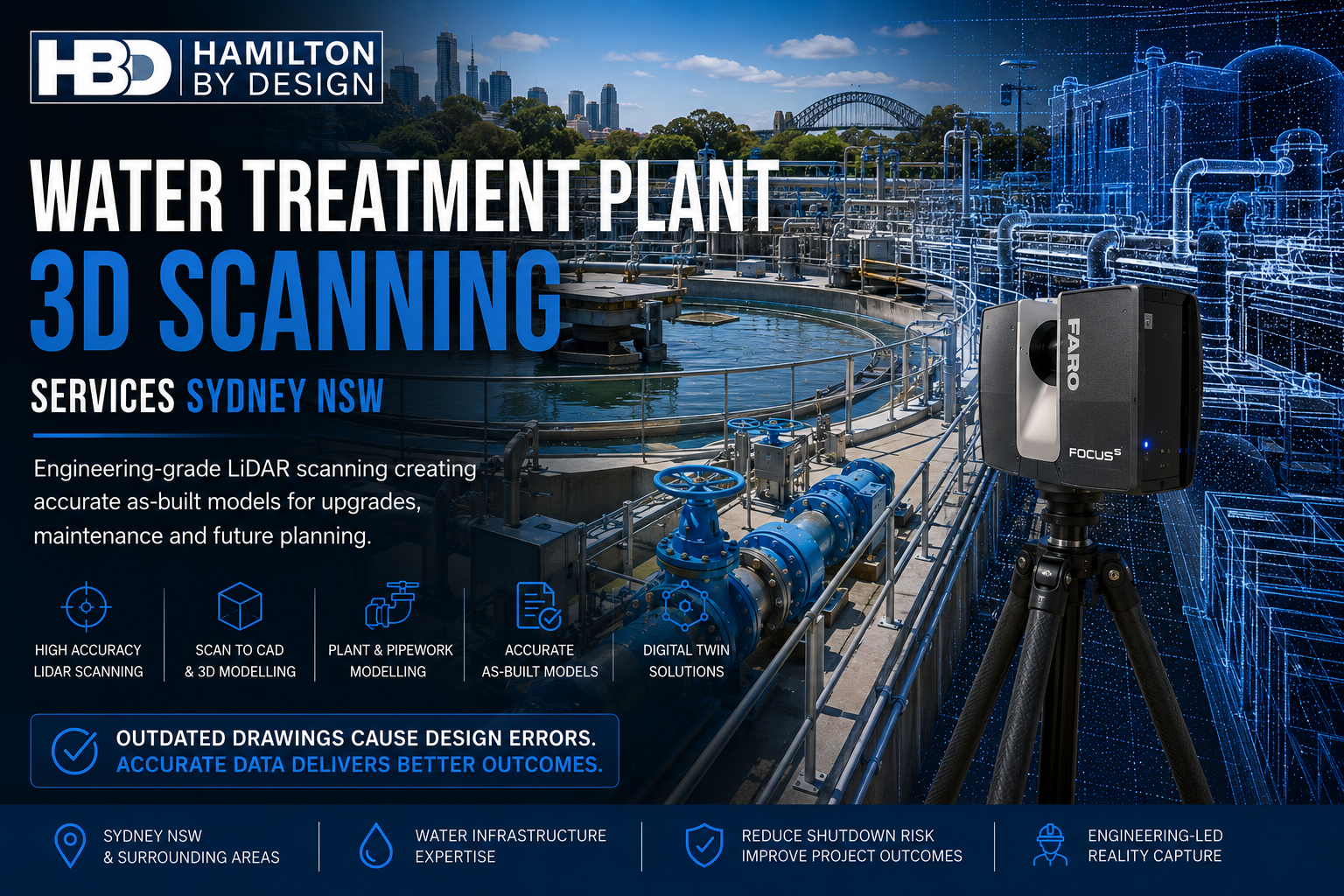
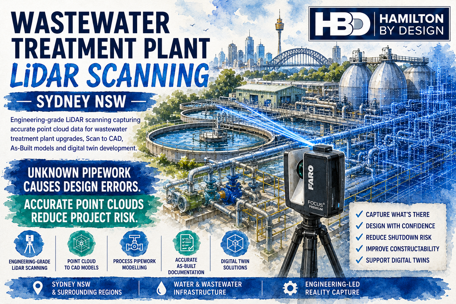
Hamilton By Design provides engineering-grade Wastewater Treatment Plant LiDAR Scanning Services throughout Sydney NSW, delivering accurate point cloud data and reality capture that forms the foundation for reliable engineering design, Scan to CAD workflows, digital twins and future plant upgrades.
The Challenge of Existing Wastewater Infrastructure
Unlike greenfield projects where everything is designed from a clean slate, wastewater treatment plants present a true brownfield engineering environment.
Facilities are continually modified to improve capacity, meet environmental regulations and replace ageing assets. These modifications may include:
- Replacement pumps
- New process pipework
- Chemical dosing systems
- Additional valves
- Electrical upgrades
- Instrumentation changes
- Structural steel modifications
- Access platforms
- Pipe bridges
- Temporary bypass systems
- Maintenance repairs
While these improvements keep the plant operating efficiently, they also create a significant challenge.
The original drawings rarely represent the current plant configuration.
Engineers designing future upgrades often discover that equipment is not where the drawings indicate, pipework has been rerouted and structural elements have changed considerably since construction.
Why Unknown Pipework Creates Expensive Problems
Pipework is the backbone of every wastewater treatment plant.
Unknown pipe locations can create serious engineering issues including:
- Pipe clashes during installation
- Incorrect spool fabrication
- Valve interference
- Equipment access restrictions
- Foundation conflicts
- Structural clashes
- Maintenance clearance problems
- Shutdown delays
- Additional site welding
- Emergency redesign
Even a small discrepancy in pipe alignment can require extensive fabrication changes during installation.
These problems become significantly more expensive once contractors are mobilised and the plant is offline.
Engineering LiDAR Scanning Removes Uncertainty
Hamilton By Design uses high-resolution terrestrial LiDAR scanners to accurately capture the entire wastewater treatment facility.
Rather than collecting isolated survey points, LiDAR scanning records millions of highly accurate measurements across every visible surface.
This includes:
- Process pipework
- Pumps
- Blowers
- Clarifiers
- Digesters
- Tanks
- Screens
- Conveyors
- Valves
- Structural steel
- Pipe supports
- Access platforms
- Handrails
- Stairways
- Electrical switchrooms
- Cable trays
- Instrumentation
- Concrete structures
The result is a highly detailed point cloud representing the facility exactly as it exists today.
Engineering Applications
Plant Upgrades
As treatment capacity increases, plants require continual expansion.
LiDAR scanning provides engineers with accurate existing-condition data before detailed design begins.
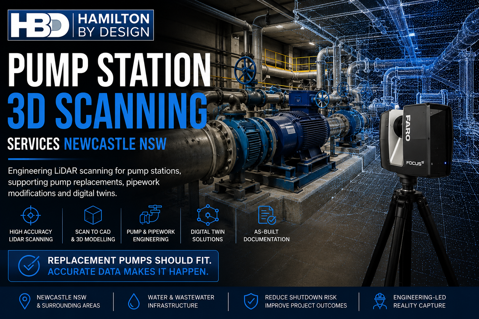
Pump Replacements
Pump replacement projects benefit from accurate verification of:
- Baseplate locations
- Pipe flange alignment
- Maintenance clearances
- Motor access
- Lifting paths
Replacement equipment can be designed around actual site conditions rather than outdated drawings.
Pipework Modifications
New process improvements frequently require:
- Additional pipelines
- Larger pipe diameters
- Bypass systems
- New isolation valves
- Flow measurement equipment
- Chemical dosing lines
Point cloud data ensures new pipework integrates correctly with existing infrastructure.
Structural Modifications
Engineering upgrades often require:
- New maintenance platforms
- Pipe supports
- Equipment frames
- Walkways
- Ladders
- Access stairs
LiDAR scanning accurately captures existing structural steel for seamless integration.
Electrical and Instrumentation
Reality capture also supports:
- Cable tray routing
- MCC upgrades
- Instrument relocation
- Electrical design
- Control system upgrades
Designers can verify available space before construction begins.
Accurate Point Cloud Data for Engineering Design
The value of LiDAR scanning extends well beyond visualisation.
Accurate point cloud data enables engineers to:
- Measure existing equipment
- Verify pipe routing
- Confirm elevations
- Check structural geometry
- Review maintenance access
- Identify clashes
- Plan installations
- Validate design assumptions
Because measurements can be taken directly from the point cloud, engineers spend less time returning to site and more time designing solutions.
Scan to CAD Services
Hamilton By Design transforms point cloud data into engineering-ready deliverables.
Typical outputs include:
- Intelligent 3D CAD models
- General Arrangement drawings
- Equipment layouts
- Pipework models
- Structural steel models
- Plant sections
- Elevations
- Fabrication drawings
- Asset registers
- As-built documentation
These deliverables integrate with modern engineering software including SOLIDWORKS, Autodesk Inventor, AutoCAD, Navisworks and ReCap.
Supporting Digital Twin Development
Water utilities across Australia are increasingly adopting digital twin technology.
LiDAR scanning provides the accurate geometric foundation for these digital assets.
Digital twins support:
- Asset management
- Maintenance planning
- Capital works
- Lifecycle management
- Operator training
- Shutdown planning
- Future engineering design
- Regulatory compliance
Instead of relying on historical drawings, digital twins represent the facility exactly as it exists.
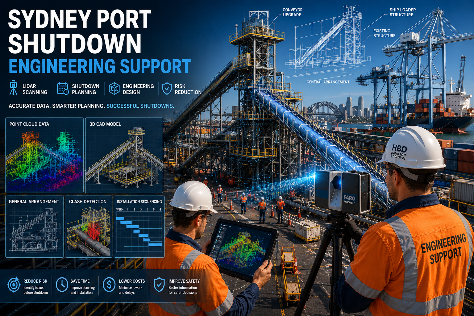
Reducing Shutdown Risk
Wastewater treatment plants typically operate continuously, making shutdown windows extremely valuable.
Every hour of delay increases project costs.
Engineering-grade LiDAR scanning reduces shutdown risk by allowing designers to:
- Verify equipment locations
- Perform clash detection
- Optimise installation sequences
- Confirm maintenance access
- Validate fabrication before delivery
Many construction issues can therefore be resolved during design rather than during installation.
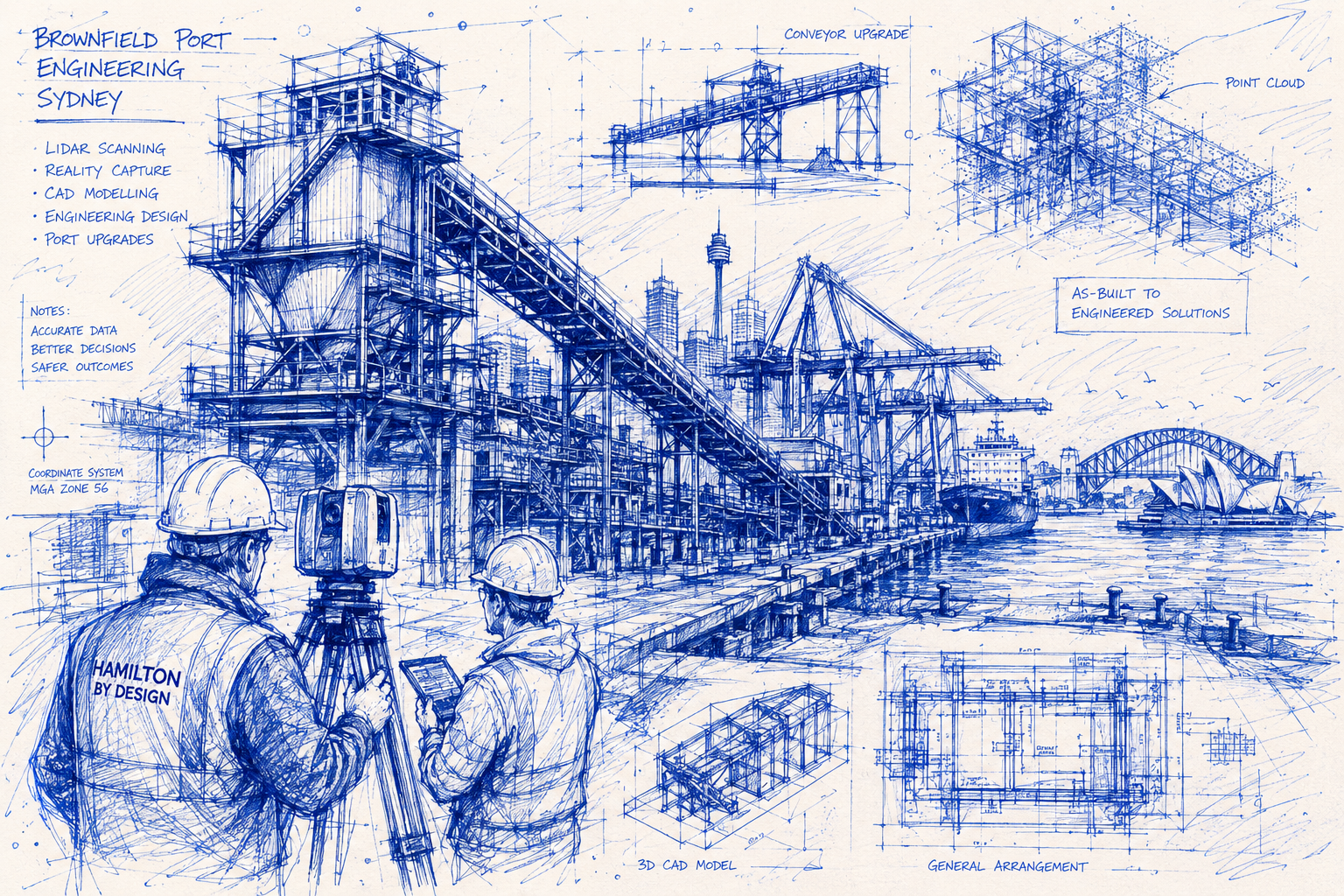
Supporting Brownfield Engineering Projects
Brownfield engineering demands accurate information.
Hamilton By Design supports projects including:
- Plant expansions
- Process upgrades
- Mechanical replacements
- Structural modifications
- Pipework redesign
- Electrical upgrades
- Asset verification
- Condition assessments
Accurate reality capture significantly improves engineering confidence throughout the project lifecycle.
Typical Workflow
Our wastewater treatment plant scanning workflow includes:
1. Project Planning
Review project objectives, operational constraints and shutdown requirements.
2. Site LiDAR Scanning
Capture all required plant areas using engineering-grade terrestrial laser scanning.
3. Point Cloud Registration
Register individual scans into one accurate coordinate system.
4. Quality Assurance
Verify scan accuracy, completeness and registration quality.
5. Engineering Modelling
Develop CAD models, layouts and engineering documentation from the point cloud.
6. Design Integration
Use verified existing conditions for mechanical, structural and process design.
7. Construction Verification
Review proposed modifications against existing infrastructure before fabrication.
Why Choose Hamilton By Design?
Hamilton By Design combines engineering expertise with advanced reality capture technology.
Our capabilities include:
- Engineering-grade terrestrial LiDAR scanning
- Wastewater infrastructure surveying
- Scan to CAD
- Reverse engineering
- Mechanical engineering
- Structural engineering support
- Engineering drafting
- As-built documentation
- Digital twin development
- Brownfield engineering
- Shutdown planning support
Because our team understands industrial engineering, we capture the information designers actually require—not simply visual data.
Supporting Sydney’s Wastewater Infrastructure
Sydney’s wastewater treatment plants are critical to protecting public health, supporting population growth and maintaining environmental compliance. As these facilities continue to modernise, reliable engineering information becomes essential for successful upgrades.
Unknown pipework and undocumented equipment locations should never compromise engineering design.
Engineering-grade LiDAR scanning provides accurate point cloud data that replaces uncertainty with confidence. By capturing every visible asset in its true position, Hamilton By Design helps engineers reduce design errors, improve constructability and minimise costly site modifications.
Whether your project involves replacing pumps, upgrading treatment processes, modifying pipework or developing a digital twin, our engineering-led LiDAR scanning services deliver the accurate existing-condition data required for successful project outcomes.
If you’re planning a wastewater treatment plant upgrade in Sydney NSW, Hamilton By Design can provide the engineering-grade reality capture, Scan to CAD modelling and As-Built documentation needed to ensure your design is based on the facility as it exists today—not as it was drawn years ago.
Talk to Us – Contact Us
Our clients:


Talk to Us – Contact Us
Our clients: