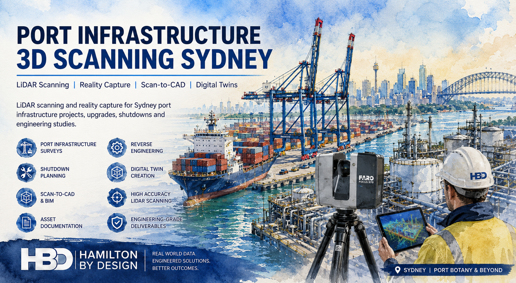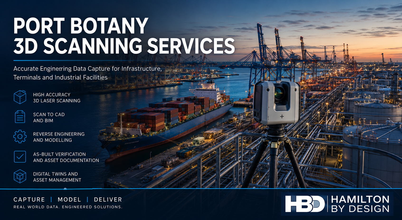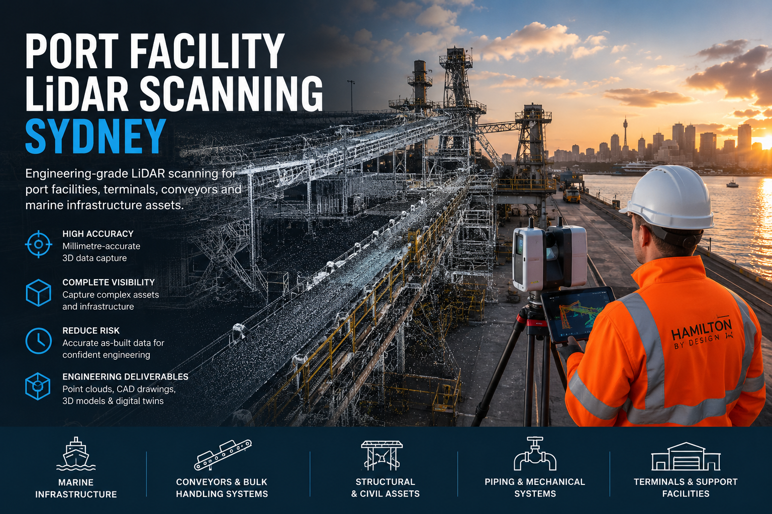

Hamilton By Design provides engineering-grade LiDAR scanning services for port facilities, container terminals, bulk handling infrastructure, marine assets and industrial facilities throughout Sydney. Our team specialises in capturing highly accurate three-dimensional data of existing infrastructure to support engineering design, asset management, maintenance planning, shutdown projects, brownfield upgrades and digital asset documentation.
Using advanced terrestrial LiDAR scanning technology, we capture millions of measurement points across complex operating environments to create accurate digital representations of port infrastructure. The resulting point clouds can be used for Scan-to-CAD, Scan-to-BIM, reverse engineering, structural analysis, mechanical design and asset verification projects.
Whether you require the scanning of conveyors, ship loaders, wharves, transfer stations, pipework systems, warehouses, structural steelwork or entire port terminals, Hamilton By Design delivers reliable and engineering-ready data suitable for detailed design and project execution.
LiDAR Scanning Services for Sydney Port Infrastructure
Sydney’s ports and marine facilities are critical infrastructure assets that operate continuously and often undergo maintenance, expansion and upgrade projects. Accurate as-built information is essential when designing modifications or integrating new equipment into existing facilities.
Our Port Facility LiDAR Scanning Sydney services support:
- Container terminals
- Bulk handling facilities
- Cargo handling infrastructure
- Conveyor systems
- Wharf structures
- Marine loading facilities
- Pump stations
- Transfer towers
- Ship loading systems
- Warehouses and storage facilities
- Structural steel infrastructure
- Maintenance workshops
- Utilities and services infrastructure
By creating accurate digital representations of existing assets, project teams can significantly reduce design risks and avoid costly site rework.
Why LiDAR Scanning Is Important for Port Facilities
Many Sydney port facilities have evolved over decades, with infrastructure expanded, modified and upgraded numerous times. Existing drawings are often incomplete, outdated or missing altogether.
Traditional site measurement methods can be time-consuming, disruptive and prone to error. LiDAR scanning provides a safer and more efficient alternative by rapidly capturing millions of accurate measurements across large and complex environments.
Benefits include:
- Reduced site visits
- Improved safety outcomes
- Accurate as-built documentation
- Faster engineering design
- Reduced rework during construction
- Improved project planning
- Enhanced clash detection
- Better asset management
The result is a highly detailed digital record that can be referenced throughout the lifecycle of an asset.
Typical Port Assets We Scan
Hamilton By Design regularly scans a wide range of marine, mechanical, structural and civil infrastructure.
Marine Infrastructure
Our scanning services are ideal for:
- Wharves
- Berths
- Jetties
- Piers
- Fender systems
- Mooring structures
- Marine access platforms
- Cargo loading facilities
These assets can be accurately captured and modelled to support maintenance and upgrade projects.
Mechanical Infrastructure
Port facilities often contain extensive mechanical systems requiring accurate documentation and modelling.
Common assets include:
- Conveyors
- Chutes
- Hoppers
- Stackers
- Reclaimers
- Crushers
- Transfer stations
- Pump systems
- Pipework networks
- Valves and fittings
Detailed point clouds enable engineers to develop accurate retrofit and replacement designs with confidence.
Structural Infrastructure
Structural scanning projects commonly include:
- Structural steelwork
- Conveyor gantries
- Access platforms
- Walkways
- Handrails
- Maintenance structures
- Warehouses
- Industrial buildings
The captured data can be converted into CAD models and engineering drawings for future projects.
Engineering Applications
LiDAR scanning data provides valuable input for a wide range of engineering activities.
Scan to CAD
Point cloud data can be converted into:
- 2D CAD drawings
- General arrangement drawings
- Sections and elevations
- Site layouts
- Equipment layouts
These deliverables provide a reliable foundation for engineering projects.
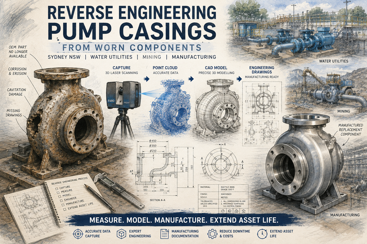
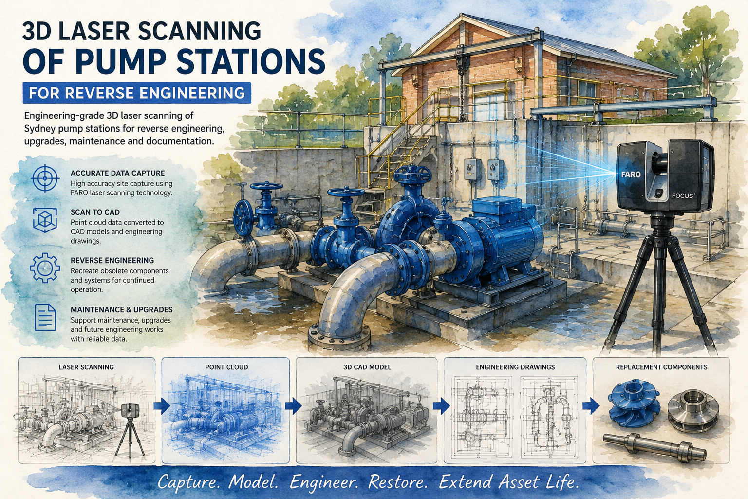
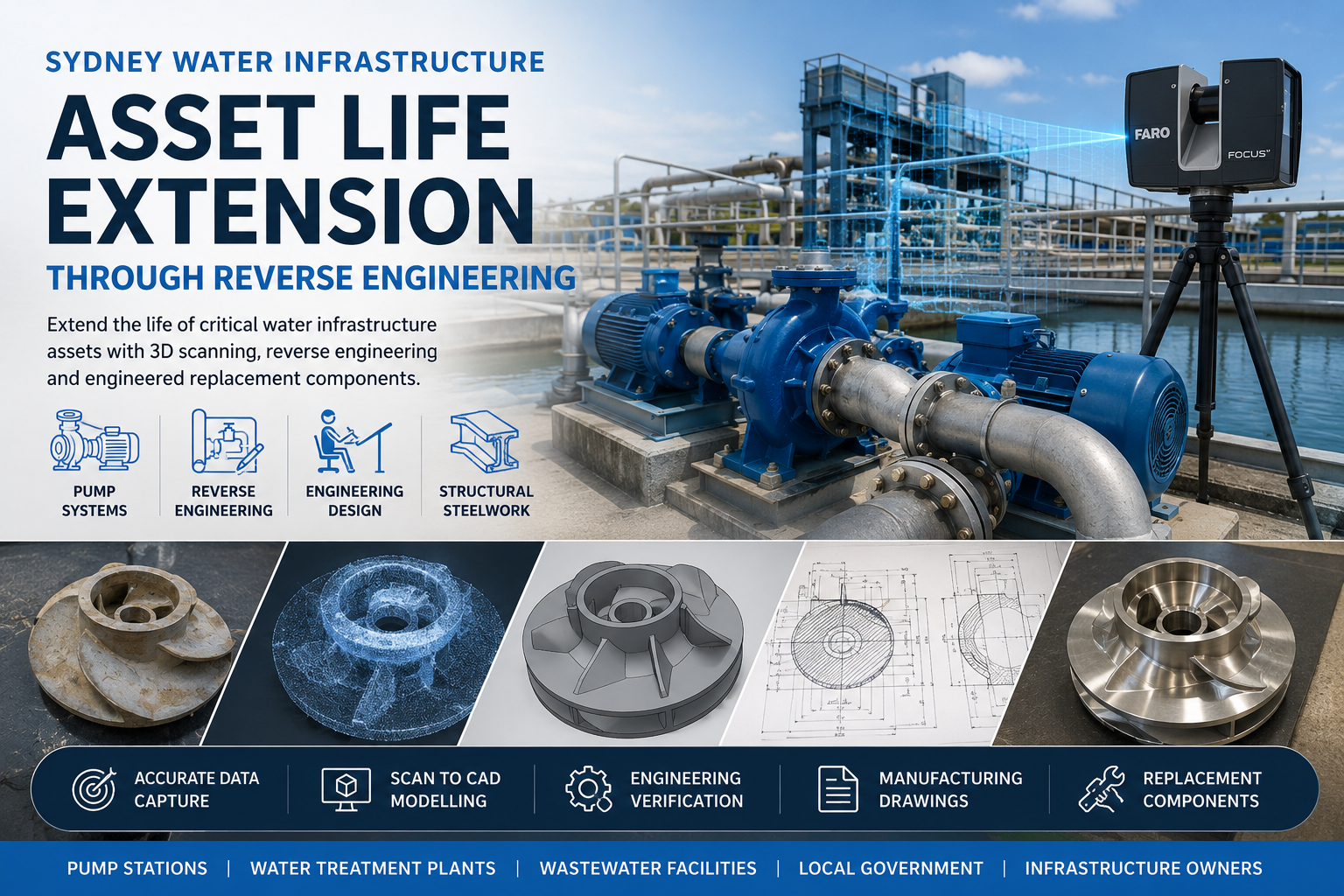
Reverse Engineering
Where original drawings are unavailable, scanned assets can be reverse engineered to create:
- 3D CAD models
- Manufacturing drawings
- Replacement component designs
- Equipment upgrades
- Legacy asset documentation
This approach is particularly valuable for ageing port infrastructure and obsolete equipment.
Brownfield Upgrade Projects
Many port facilities remain operational while upgrade works are undertaken.
LiDAR scanning enables engineers to:
- Verify available space
- Identify clashes
- Validate clearances
- Design around existing infrastructure
- Improve constructability
The result is reduced project risk and improved installation outcomes.
Our LiDAR Scanning Process
1. Project Planning
We begin by reviewing project requirements, site access constraints and deliverable expectations.
This stage identifies:
- Scan coverage requirements
- Safety considerations
- Access restrictions
- Accuracy requirements
- Final deliverables
2. Site Data Capture
Using professional LiDAR scanning equipment, we capture millions of accurate measurements throughout the facility.
Data collection may include:
- Terrestrial laser scanning
- High-density point cloud capture
- Structural scanning
- Mechanical equipment scanning
- Infrastructure scanning
Large facilities can be captured efficiently while minimising disruption to operations.
3. Point Cloud Registration
Following site capture, scans are processed and registered into a unified coordinate system.
This process creates:
- Registered point clouds
- Quality assurance reports
- Survey-aligned datasets
- Engineering-ready deliverables
4. Modelling and Documentation
The point cloud data can then be converted into engineering deliverables including CAD drawings, BIM models and 3D asset models.
Deliverables
Hamilton By Design can provide a range of deliverables depending on project requirements.
Point Cloud Deliverables
- E57
- RCP
- RCS
- LAS
- LGS
CAD Deliverables
- DWG drawings
- DXF drawings
- Site plans
- General arrangements
- Sections and elevations
3D Models
- SolidWorks models
- STEP files
- SAT files
- Navisworks models
- BIM models
Engineering Deliverables
- Asset documentation
- Clash detection reports
- As-built verification
- Reverse engineering models
- Upgrade design support
Industries We Support
Our Port Facility LiDAR Scanning Sydney services support a broad range of industries including:
- Ports and marine infrastructure
- Logistics and transport
- Manufacturing
- Mining and bulk materials handling
- Utilities
- Water infrastructure
- Industrial facilities
- Government infrastructure
- Engineering consultancies
- Construction contractors
Our engineering background allows us to understand how scanning data will ultimately be used within design, maintenance and asset management workflows.
Why Choose Hamilton By Design
Hamilton By Design combines practical engineering experience with advanced reality capture technology. Unlike survey-only providers, our team understands how point cloud data is used throughout engineering projects, from concept design through to fabrication and installation.
We provide engineering-focused LiDAR scanning services that support real-world project outcomes, helping clients reduce risk, improve accuracy and accelerate project delivery.
Whether you require a conveyor scanned for a shutdown project, a wharf documented for refurbishment works, or an entire port facility captured for future upgrades, Hamilton By Design delivers accurate, reliable and engineering-ready data across Sydney and surrounding regions.

Contact Hamilton By Design
If you require Port Facility LiDAR Scanning in Sydney, contact Hamilton By Design to discuss your project requirements. We provide engineering-grade reality capture, Scan-to-CAD, reverse engineering and infrastructure documentation services for port operators, contractors and engineering consultants throughout Sydney and Australia.
Talk to Us – Contact Us
Our clients: