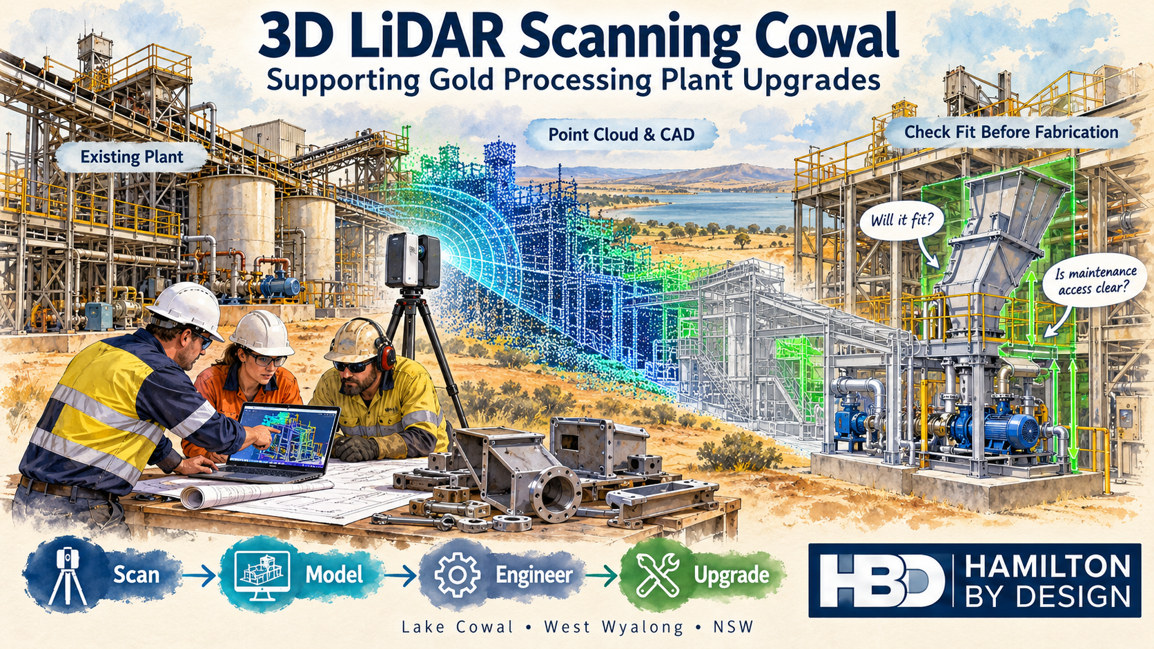
3D LiDAR Scanning Cowal โ€“ Supporting Gold Processing Plant Upgrades

Watercolour illustration of 3D LiDAR scanning for Cowal gold processing plant upgrades, showing a scanner, point cloud, CAD model and Hamilton By Design logo.
Blue 3D LiDAR scanner icon on a tripod with scanning waves

Hamilton By Design offers 3D LiDAR scanning in the Cowal and West Wyalong region to support mechanical engineering, equipment replacement and gold processing plant upgrades. By capturing existing plant geometry before design begins, we help project teams understand available space, assess equipment interfaces and plan modifications with greater confidence.

From a replacement transfer chute to a new pump skid or revised pipe route, reliable information about the existing installation provides a stronger starting point for engineering and fabrication.

Our approach is straightforward: scan โ†’ model โ†’ engineer โ†’ upgrade.

Supporting Gold Processing Projects Near Lake Cowal

Evolution Miningโ€™s Cowal Gold Operations is located near Lake Cowal, approximately 40 kilometres northeast of West Wyalong in New South Wales. The operation includes both open-pit and underground gold mining.

For contractors and engineering teams working on established processing plants, an important challenge is understanding how proposed equipment will fit around the existing installation.

Original drawings provide useful background, but subsequent modifications may have changed pipe routes, equipment positions, access platforms and support arrangements. A new component designed from incomplete information can encounter unexpected clashes during installation.

Hamilton By Design provides scanning and mechanical design services that can support projects in this region, helping teams establish existing conditions before committing to fabrication.

Why Scan Before Designing a Plant Upgrade?

A processing plant upgrade involves more than finding space for a new machine. The design also needs to consider its connections, surrounding equipment, installation route and future maintenance access.

3D LiDAR scanning captures visible surfaces as a point cloud. This creates a spatial record that can be reviewed, measured and used as a reference within compatible CAD software.

Depending on the agreed scope and site access, scanning can help establish:

  • Existing equipment positions and surrounding geometry.
  • Conveyor and transfer chute interfaces.
  • Pipe routes and accessible connection locations.
  • Platform, stair and walkway arrangements.
  • Visible steelwork and support locations.
  • Space around pumps, tanks and mechanical equipment.
  • Potential clashes between proposed and existing installations.
  • Clearances for maintenance and component removal.

Capturing these details early helps the design team identify questions while there is still time to resolve them.

Checking Component Fit Before Fabrication

One of the most useful applications of 3D LiDAR scanning Cowal is checking proposed components against the existing plant.

For example, a replacement chute may need to connect to an existing conveyor discharge, pass through a platform opening and avoid nearby pipework. Each interface affects the final design.

Using a registered point cloud, Hamilton By Design can develop a CAD model of the relevant area and position the proposed component within it.

This allows the project team to review questions such as:

  • Does the component fit within the available space?
  • Do its inlet and outlet positions suit the existing equipment?
  • Are there clashes with steelwork, pipes or platforms?
  • Can personnel reach inspection and maintenance points?
  • Is there enough room to remove liners, motors or other serviceable parts?
  • Does installation require temporary removal of surrounding equipment?

Checking fit in the model helps reduce uncertainty before steel is cut and equipment arrives on site.

Critical interfaces still need an agreed measurement and verification approach, particularly where tight tolerances apply.

Conveyor and Transfer Chute Modifications

Conveyors and transfer chutes bring together several mechanical interfaces within a relatively small area.

A modification may need to accommodate existing conveyor geometry, support steelwork, liner arrangements, access doors and nearby services. Measuring each feature separately can make it difficult to understand their relationship.

3D scanning provides a common spatial reference for reviewing the installation.

Hamilton By Design can use scan data to support:

  • Replacement transfer chute layouts.
  • Conveyor discharge and receiving interfaces.
  • Chute relocation and connection geometry.
  • Wear liner and access door arrangements.
  • Guarding layouts.
  • Maintenance access reviews.
  • General arrangement and fabrication drawings.

The point cloud establishes the visible geometry. Mechanical design then considers operating requirements, material characteristics and the intended function of the equipment.

Pump Skids, Pipework and Equipment Replacement

Replacing a pump or installing a new skid can affect more than its immediate footprint.

Suction and discharge connections, surrounding pipework, motor access, lifting arrangements and maintenance space all influence the layout.

A scan of the installation area can help the design team assess these relationships before selecting a final arrangement.

Typical applications include:

  • Positioning replacement pump skids.
  • Reviewing accessible pipe connection locations.
  • Developing preliminary pipe routes.
  • Checking equipment footprints.
  • Assessing space for valves and maintenance tasks.
  • Identifying clashes with existing services.
  • Preparing coordinated mechanical layouts.

Where flange faces, bolt patterns or other connection details are critical, additional measurements may be required. The capture method should match the tolerance needed for the job.

Scan-to-CAD for Gold Processing Plant Upgrades

A point cloud is a valuable reference, but many projects also need a practical CAD model.

Hamilton By Design can convert selected scan geometry into a model suitable for the agreed design task. This may involve modelling an equipment installation, a transfer area or the surrounding plant layout.

The level of detail should reflect the projectโ€™s purpose.

A preliminary layout may only need equipment envelopes and major obstacles. A replacement component may require more detailed modelling of its connection points and surrounding interfaces.

Depending on the scope, deliverables can include:

  • Registered point clouds in agreed formats, such as E57 or RCP.
  • Selected existing-condition CAD models.
  • Proposed mechanical equipment models.
  • General arrangement drawings.
  • Fabrication drawings for agreed components.
  • STEP, DXF or other compatible CAD files.
  • PDF drawing packs for review and coordination.

Agreeing on the intended use of the data at the start helps ensure that scanning and modelling capture the information the project actually needs.

Planning Work Around Shutdowns

Shutdown installation periods place pressure on maintenance teams, fabricators and contractors. Discovering an unexpected clash during that window can lead to urgent modifications and additional work.

Scanning ahead of a shutdown gives the project team an opportunity to review the installation while design changes are still manageable.

A coordinated model can help teams assess:

  • Component delivery and installation routes.
  • Available space for assembly.
  • Nearby equipment that may restrict access.
  • Interfaces requiring confirmation.
  • Temporary removal requirements.
  • The proposed installation sequence.

Scanning access must be coordinated with site personnel. Equipment isolation, permits, elevated access and operating conditions may affect what can be captured and when.

Early planning helps establish a realistic scope and identify areas that require a separate visit or shutdown access.

Matching Accuracy to the Engineering Task

Different engineering tasks require different levels of measurement detail.

Plant layout scanning can provide a useful record of equipment positions and surrounding geometry. Small machined features, bolt holes and precision mating surfaces may require closer inspection, direct measurement or a suitable metrology scanning method.

For each project, Hamilton By Design considers:

  • The dimensions that matter to the design.
  • The required fit and tolerance.
  • Scanner access and viewing angles.
  • Surface conditions and visibility.
  • Registration requirements.
  • Features requiring supplementary measurement.

LiDAR captures visible surfaces. Hidden connections, internal geometry and obscured areas need further investigation where they affect the design.

The aim is to provide information suitable for the engineering decision being made.

A Practical Workflow from Site Capture to Drawings

Hamilton By Design combines scanning with mechanical engineering and drafting support.

Our workflow starts by defining the proposed modification and identifying its critical interfaces. We then plan the site capture, register the scan data and develop the models needed for review.

Once the proposed arrangement has been assessed and key details confirmed, drawings can be prepared for the agreed fabrication or installation scope.

This connects the site information to a practical outcome: a better-informed design, clearer drawings and fewer unresolved fit-up questions.

Frequently Asked Questions

Can 3D LiDAR scanning help check whether new equipment will fit?

Yes. Scan data can be used as a reference for positioning proposed equipment and checking surrounding clearances. Critical dimensions and interfaces should be verified to suit the required tolerance.

Can you develop fabrication drawings from scan data?

Yes. Hamilton By Design can develop selected CAD models and fabrication drawings from suitable scan data, subject to the agreed scope and confirmation of critical details.

Does the entire processing plant need to be scanned?

No. A targeted scan may be sufficient for a replacement chute, pump installation or local pipework modification. Wider capture can be useful where the project involves several connected areas.

Can scanning take place while the plant is operating?

Some areas may be accessible during operation, subject to site approval and safe access. Other areas may require isolation or shutdown access to capture the necessary geometry.

Can you work with existing point clouds?

Yes. Supplied point clouds can be reviewed for coverage, registration quality and suitability. Additional scanning or measurement may be needed where important interfaces are missing or unclear.

Discuss Your Cowal Plant Upgrade

Planning an equipment replacement, conveyor modification, transfer chute upgrade or pipework installation near Cowal or West Wyalong?

Hamilton By Design can help establish the existing geometry and develop the mechanical models and drawings needed to progress the project.

Send us an outline of the proposed work, site photographs and any available drawings or point cloud data. We can then assess the capture requirements and recommend an appropriate scope.

Contact Hamilton By Design to discuss 3D LiDAR scanning, scan-to-CAD and mechanical engineering support for your Cowal project.


Hamilton By Design logo displayed on a blue tilted rectangle with a grey gradient background

Contact Us – Talk To Us

Name
Would you like us to arrange a phone consultation for you?
Address

Our clients:
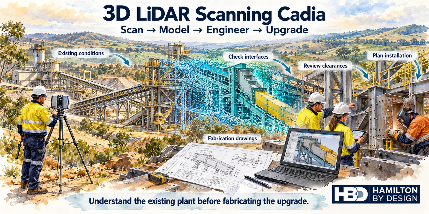


3D LiDAR Scanning for Cadia Mining and Processing Plant Projects

Watercolour illustration of 3D LiDAR scanning for Cadia plant upgrades, showing a scanner, point cloud model, fabrication drawings and engineers checking component fit.
Blue line icon of a tripod-mounted LiDAR scanner surveying a mineral processing plant with a hopper, conveyors and transfer chute.

Hamilton By Design offers 3D LiDAR scanning for Cadia mining and processing plant projects, helping engineers, maintenance teams and fabrication contractors understand existing plant geometry before designing and installing modifications.

From replacement chutes and conveyor interfaces to pump skids and pipework, successful upgrades depend on knowing what is already there. A registered point cloud provides a detailed spatial reference for developing designs, checking clearances and planning installation.

Our approach connects scan โ†’ model โ†’ engineer โ†’ upgrade, turning captured site geometry into practical engineering information.

Supporting Mining Projects Around Cadia and Orange

Cadia is a major gold and copper mining operation owned by Newmont, located approximately 25 kilometres from Orange in Central West NSW. Its scale and industrial setting make existing plant information an important consideration for maintenance and upgrade planning.

For projects in this environment, drawings may need to be checked against equipment that has changed over time. Added pipework, modified supports, replacement machinery and altered access arrangements can affect how a new component fits.

Hamilton By Design can support project teams working in the Cadia and Orange region with site scanning, point cloud processing, mechanical modelling and drawing development. Site work is arranged around the agreed scope, access requirements and operating conditions.

Why Scan Before Designing a Plant Upgrade?

A replacement component may match the original drawing yet still clash with the current installation.

Common sources of uncertainty include:

  • Connection points that differ from the drawings.
  • Pipework or cable trays crossing the proposed installation area.
  • Limited clearance around conveyors and transfer points.
  • Existing steelwork affecting equipment placement.
  • Restricted access for lifting, assembly and maintenance.
  • Changes made during previous shutdowns.

3D LiDAR scanning captures visible surfaces across the work area, allowing the proposed design to be reviewed against its surroundings.

This helps project teams identify potential problems earlier, when changes are generally easier to manage than during fabrication or installation.

3D LiDAR Scanning for Chutes and Conveyor Interfaces

Chute replacements and conveyor modifications require more than the dimensions of the component being replaced. The surrounding arrangement influences the design, installation sequence and future maintenance access.

Scanning can capture:

  • Conveyor positions and transfer point geometry.
  • Existing chute envelopes and accessible connections.
  • Supporting steelwork and nearby platforms.
  • Adjacent services and equipment.
  • Available space for removal and installation.

The point cloud can then support a mechanical model of the proposed arrangement.

For example, a replacement transfer chute can be reviewed against surrounding steelwork, pipework and access platforms before drawings are issued for fabrication. Critical connection dimensions can be identified for additional verification.

Pump Skids, Pipework and Service Modifications

Installing a new pump or changing a pipe route can create challenges in a congested processing plant.

An existing layout may provide enough space for the equipment itself while leaving insufficient room for valves, maintenance activities or removal of major components.

A scan-based model can help assess:

  • Pump skid placement and surrounding clearances.
  • Accessible flange locations and pipe routes.
  • Potential clashes with existing equipment.
  • Space for valve operation and maintenance.
  • Proposed support locations.
  • Installation and component removal paths.

Capturing the surrounding area provides context for these decisions. It helps the designer consider how the equipment will be installed, operated and maintained.

Scan-to-CAD for Mechanical Design and Fabrication

A point cloud becomes more useful when it is connected to the required engineering deliverable.

Hamilton By Design can use registered scan data as a reference for developing CAD models in SolidWorks and AutoCAD. Depending on the project scope, deliverables may include:

  • Registered point clouds.
  • Models of selected existing equipment.
  • Proposed mechanical equipment models.
  • General arrangement drawings.
  • Fabrication and assembly drawings.
  • Interface details and dimensional review information.
  • STEP, DXF or other agreed CAD exchange files.

The level of modelling is selected to suit the task. A layout study may need equipment envelopes and principal interfaces, while a fabrication package requires more detailed geometry and verified connection information.

This keeps the work focused on the decisions the project team needs to make.

Planning Component Fit Before Fabrication

One of the most useful applications of 3D LiDAR scanning at Cadia is checking the proposed component against the existing plant before fabrication begins.

A typical workflow is:

  1. Define the interfaces: Identify connection points, critical dimensions and required clearances.
  2. Capture the work area: Scan the component location and relevant surrounding equipment.
  3. Register and review the data: Check coverage and identify areas requiring further measurement.
  4. Develop the model: Position the proposed component within the existing geometry.
  5. Review fit and access: Assess clashes, assembly requirements and maintenance space.
  6. Prepare the drawings: Document the agreed arrangement and fabrication details.

Scanning supports fit-up planning, but concealed surfaces and fine features may require additional measurement. Bolt holes, machined faces and tight tolerance connections should be assessed individually rather than assumed to be fully defined by a general plant scan.

Supporting Shutdown and Installation Planning

Shutdown work benefits from early decisions about component fit, removal routes and installation access.

A scan-based model can help teams consider questions such as:

  • Can the existing component be removed through the available opening?
  • Will the replacement need to be installed in sections?
  • Does nearby pipework restrict the installation path?
  • Is there enough space to access the connections?
  • Which dimensions need verification before fabrication?

These reviews can support discussions between engineering, maintenance, fabrication and installation teams.

Scanning is most valuable when completed early enough for the findings to influence the design and work plan.

Accuracy Matched to the Engineering Task

The required accuracy should be established before scanning begins.

A broad plant layout study has different requirements from a replacement component with tightly controlled interfaces. Scan coverage, distance, surface condition, visibility and registration all affect the usefulness of the resulting data.

Hamilton By Design works with the project team to identify:

  • The purpose of the scan.
  • Critical interfaces and tolerances.
  • Areas requiring detailed capture.
  • Features needing supplementary measurement.
  • Required file formats and drawing outputs.

This creates a clear basis for the work and helps distinguish captured geometry from dimensions that still need verification.

Frequently Asked Questions

Can scanning help check whether a replacement chute will fit?

Yes. A point cloud can support a model of the replacement chute within the surrounding plant. This helps identify clashes and access constraints. Critical fabrication interfaces may also need direct measurement.

Can you work from an existing point cloud?

Yes. Hamilton By Design can review supplied scan data for modelling and drawing development. Its suitability depends on coverage, registration quality and the detail available around the required interfaces.

Does every scanned item need to be modelled?

No. Modelling can focus on the equipment, surfaces and connections relevant to the project. The remaining point cloud can provide surrounding context.

Can scanning take place while the plant is operating?

This depends on site approval, access and conditions. Moving equipment, dust, vibration and obstructed views may limit capture. Some areas may require isolation or shutdown access.

Can you provide drawings as well as scanning?

Yes. The scope can include point cloud processing, mechanical modelling, general arrangements and fabrication drawings, with deliverables agreed before work begins.

Discuss Your Cadia Scanning Project

Planning a chute replacement, conveyor modification, pump installation or processing plant upgrade near Cadia?

Contact Hamilton By Design to discuss 3D LiDAR scanning, scan-to-CAD modelling and mechanical design support.

Send photographs, existing drawings and a brief description of the proposed work so we can identify the required scan coverage, critical interfaces and suitable deliverables.

Capture the existing plant. Check the proposed fit. Develop the upgrade with better information.


Hamilton By Design logo displayed on a blue tilted rectangle with a grey gradient background

Contact Us – Talk To Us

Name
Would you like us to arrange a phone consultation for you?
Address

Our clients:


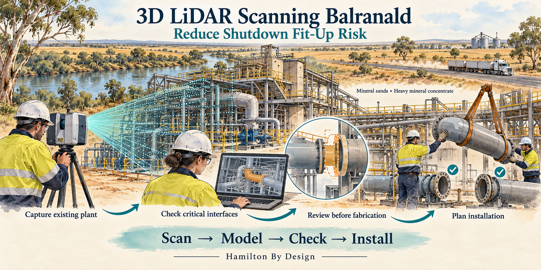
3D LiDAR Scanning Balranald NSW โ€“ Reduce Shutdown Fit-Up Risk

Watercolour illustration of 3D LiDAR scanning at a mineral processing plant in Balranald NSW, showing component checks and shutdown installation planning.
Blue 3D LiDAR scanner icon on a tripod with scanning waves

Check how replacement components connect to existing plant before fabrication and installation.

Hamilton By Design provides 3D LiDAR scanning, scan-to-CAD modelling and mechanical design services for mineral processing facilities in Balranald and south-western NSW.

For maintenance teams, engineering contractors and fabricators, the objective is practical: understand the installed geometry, check critical interfaces and identify clashes before equipment arrives on site.

Whether replacing a chute, modifying slurry pipework or installing a new pump skid, early scanning can help reduce the risk of components requiring unexpected modification during a shutdown.

Supporting Balranaldโ€™s Mineral Sands Industry

Ilukaโ€™s Balranald operation is located approximately 12 kilometres northwest of Balranald in south-western NSW. The mineral sands deposits contain rutile, zircon and rare earth-bearing minerals, with an on-site concentrating plant producing heavy mineral concentrate for further processing.

Iluka reports that mining and processing of run-of-mine ore commenced in January 2026.

For mineral sands and heavy mineral concentrate facilities, equipment modifications need to account for the plant as it exists today. Pipework, supports, access platforms and neighbouring equipment can all influence whether a replacement assembly fits.

Hamilton By Design offers scanning and mechanical design support for operators and contractors undertaking this type of work in the Balranald region.

Will the New Component Fit the Existing Plant?

A replacement component may match its drawing yet still encounter problems during installation.

Existing equipment may have been modified, supports may sit differently from their original design positions, or surrounding services may restrict access. Older drawings may also omit changes made during previous maintenance work.

Common fit-up problems include:

  • Pipe flanges that do not align with replacement spools.
  • Chute connections that differ from the original drawings.
  • Pump skids that conflict with existing pipework or supports.
  • Brackets and mounting plates positioned differently from the design.
  • Guards that interfere with nearby equipment.
  • Components that fit their final position but cannot pass through the installation route.

3D LiDAR scanning captures visible plant geometry so these interfaces can be reviewed before fabrication.

The aim is to resolve fit-up questions while there is time to change the design.

Capture the Plant Before the Shutdown

Scanning ahead of a planned shutdown creates a spatial reference for engineering and fabrication.

The survey can focus on the equipment being replaced, its connection points and the surrounding area needed for installation and maintenance.

Depending on the project, this may include:

  • Equipment positions and external geometry.
  • Pipe routes and accessible connection points.
  • Chute inlet and outlet interfaces.
  • Existing frames and support arrangements.
  • Platforms, stairs, handrails and access restrictions.
  • Nearby equipment and services.
  • Available space for removal and installation.

Access, visibility and the required tolerances guide the scanning plan. Where operating equipment obscures critical features, additional capture may be needed during an agreed isolation or access window.

Check New Equipment Against the Point Cloud

A registered point cloud provides a three-dimensional record of the scanned area. Proposed equipment models can then be positioned within that record to assess how they connect to the existing plant.

Hamilton By Design can use this process to review:

  • Replacement chute geometry and connection locations.
  • Slurry and process pipework routes.
  • Pump skid positions and service connections.
  • Equipment support interfaces.
  • Guarding arrangements.
  • Maintenance clearances.
  • Installation envelopes and potential clashes.

For example, a replacement pipe spool can be modelled against the surveyed route, with its end connections and nearby obstructions reviewed before drawings are released.

This gives engineers, fabricators and installation teams a common reference for discussing changes.

LiDAR Scanning and Critical Fit-Up Measurements

The measurement method needs to suit the connection being checked.

LiDAR scanning is useful for capturing plant layouts, equipment envelopes and surrounding geometry. Close-tolerance features such as small bolt holes, machined faces and shaft interfaces may require supplementary measurement or higher-resolution component scanning.

Hamilton By Design can combine plant scanning with targeted checks of critical interfaces.

Before mobilisation, we establish:

  • Which components must connect.
  • The required fit-up tolerances.
  • Which surfaces and features are accessible.
  • Where supplementary measurements are needed.
  • Which dimensions require verification before fabrication.

This approach makes the scan useful for the installation decision. A clash-free model alone does not establish that every connection meets its required tolerance.

Mechanical Design for Mineral Processing Modifications

Capturing geometry is the first step. Turning it into usable engineering information helps the project move towards fabrication and installation.

Hamilton By Design can support:

Chute replacements and modifications
Model existing interfaces and develop replacement geometry around available space, connection points and maintenance access.

Pipework and spool arrangements
Capture existing routes and support positions to assist with replacement spools, rerouting and equipment connections.

Pump skids and equipment layouts
Review proposed equipment against the installed plant, including surrounding services and maintenance space.

Guarding and access arrangements
Develop geometry around existing equipment while considering inspection, maintenance and removal requirements.

Reverse engineering
Create CAD models of accessible components where suitable drawings are unavailable, with critical dimensions checked using an appropriate measurement method.

The scope can range from a focused interface survey to a broader scan-to-CAD and mechanical design package.

A Practical Workflow for Shutdown Planning

1. Define the fit-up problem

Identify the replacement equipment, connection points, shutdown constraints and required deliverables.

2. Capture the existing installation

Scan the relevant area and complete agreed supplementary measurements.

3. Build the spatial reference

Register the scan data and prepare the point cloud for engineering review.

4. Model and review the proposed components

Check interfaces,


Hamilton By Design logo displayed on a blue tilted rectangle with a grey gradient background

Contact Us – Talk To Us

Name
Would you like us to arrange a phone consultation for you?
Address

Our clients:

Mechanical Engineering and 3D LiDAR Scanning Ulaanbaatar, Mongolia

Watercolour illustration of LiDAR scanning at a conceptual mining processing plant near Ulaanbaatar, with conveyors, access platforms and Hamilton By Design branding.
Blue line icon of a tripod-mounted LiDAR scanner surveying a mineral processing plant with a hopper, conveyors and transfer chute.

Mining plant upgrades need reliable information about existing equipment, practical maintenance access and a clear engineering scope. For project teams based in Ulaanbaatarโ€”also known as Ulan Batorโ€”Hamilton By Design offers mechanical engineering, 3D LiDAR scanning and design support for mining and industrial projects, with site mobilisation arranged to suit the project.

Our approach brings together existing-condition capture, CAD modelling and engineering documentation. This helps owners, maintenance teams and fabricators plan modifications around the plant that is actually installed.

From coal handling equipment at Baganuur to gold processing infrastructure in the Borooโ€“Ulaanbulag area, potential applications include conveyor upgrades, transfer chute modifications, maintenance platforms, walkways and working-at-height systems.

Mining Operations Around Ulaanbaatar

Ulaanbaatar provides a useful geographic focus for discussing nearby mining operations, although the mines are located in outlying districts and surrounding provinces.

Four confirmed operating mines relevant to this regional overview are:

MineLocation relative to UlaanbaatarCommodityPotential engineering focus
Baganuur Coal MineApproximately 130 km east, in the outlying Baganuur districtThermal coal / ligniteCoal handling equipment, maintenance access and plant modifications
Boroo Gold MineApproximately 140 km northwest, in Selenge ProvinceGoldProcessing equipment layouts, access improvements and brownfield upgrades
Ulaanbulag Gold MineApproximately 19 km southeast of BorooGoldEquipment interfaces and infrastructure associated with the shared processing operation
Shivee-Ovoo Coal MineApproximately 260 km southeast, in Govisรผmber ProvinceThermal coal / ligniteCoal handling infrastructure, maintenance facilities and access upgrades

Baganuur and Shivee-Ovoo are operating coal mines. Boroo and Ulaanbulag are operating gold mines that share key infrastructure and processing facilities. These locations illustrate the regional mining context; they are not presented as Hamilton By Design clients.

Nalaikh is also associated with Ulaanbaatarโ€™s mining history, but its main industrial coal mine is closed. Gatsuurt is a gold development project whose current production status has not been confirmed for this overview.

Mechanical Engineering for Mining Plant Upgrades

A successful plant modification starts with understanding the operational problem.

A conveyor transfer may need improved material flow. A pump installation may require more room for servicing. A replacement chute may need to fit between existing equipment while preserving access for liner changes.

Hamilton By Designโ€™s mechanical engineering consulting services cover equipment design, CAD modelling, drafting and assessment for mining and industrial applications.

For projects coordinated from Ulaanbaatar, the scope can be developed around questions such as:

  • What equipment is being replaced or modified?
  • Which existing interfaces must be retained?
  • How will components be transported, lifted and installed?
  • What access will maintenance personnel need?
  • Which drawings and approvals are required before fabrication?

Resolving these questions early gives the project team a clearer basis for design, procurement and shutdown planning.

3D LiDAR Scanning Before Design Begins

Existing drawings are useful, but their relationship to current site conditions needs checking before a retrofit is designed.

A pipe installed during an earlier upgrade may cross the proposed platform location. A conveyor support may occupy the space needed for a new chute. Equipment removal may be restricted by steelwork that does not appear on the available drawings.

3D LiDAR scanning helps establish the spatial arrangement of visible plant and infrastructure.

The resulting point cloud can support layout development, equipment positioning and coordination between disciplines. Critical interfaces can then be selected for additional measurement or inspection where the project requires it.

Scanning is particularly useful when several modifications must fit within the same area. A shared model allows the team to review the proposed arrangement before committing to fabrication.

Hamilton By Design combines this measured information with mechanical design and scan-to-CAD workflows.

Platforms, Walkways, Stairways and Ladders

Maintenance access deserves attention at the start of a plant upgrade.

A new component may fit into the available space yet leave insufficient room for inspection, adjustment or removal. Access arrangements should therefore be developed around the tasks people will perform, rather than added after the equipment layout is complete.

For example, a chute upgrade may require a working position beside an inspection door. A conveyor drive replacement may need an access route that also accommodates handling tools and removed components.

Hamilton By Designโ€™s guide to AS 1657 fixed platforms, walkways, stairways and ladders explains the role of this Australian standard in industrial access design.

For a Mongolian project, the design basis should identify applicable local requirements, owner specifications and any contractually adopted standards. Where AS 1657 is proposed as a reference, its suitability and acceptance should be established with the projectโ€™s responsible advisers.

The objective is a coordinated arrangement that supports the intended maintenance task and can be reviewed, fabricated and installed with clear documentation.

Static Line Systems and Working-at-Height Access

Some inspection and maintenance tasks require a dedicated working-at-height solution.

Hamilton By Designโ€™s static line installation and engineering certification service describes support for system layouts, supporting-structure assessment, installation documentation and engineering verification.

For projects around Ulaanbaatar, this work should be coordinated with the selected system supplier, installer and appropriately qualified engineering reviewers. The scope needs to address how the system connects to the existing asset and how the completed installation will be verified and handed over.

The required certification and local acceptance pathway should be agreed before procurement. This gives each participant a clear understanding of their responsibilities and the evidence required for completion.

Connecting Access Improvements with Equipment Design

Access and mechanical design often affect the same space.

Consider a proposed coal transfer upgrade. The project may need a revised chute, removable guarding and a working position for inspections. Designing each item separately can leave conflicts between access routes, maintenance openings and installation requirements.

A coordinated model allows the team to examine the complete arrangement:

  1. Capture and verify the existing area.
  2. Define operating and maintenance requirements.
  3. Develop the equipment and access concepts together.
  4. Review interfaces with the owner and installation team.
  5. Prepare the agreed drawings and engineering documentation.

This approach can help identify problems while changes are still straightforward to make.

Deliverables Defined Around Your Project

A focused project may need only an equipment model and general arrangement drawing. A larger upgrade may require a coordinated package for fabrication, installation and review.

Depending on the agreed scope, deliverables may include:

  • Registered point cloud data.
  • Existing-condition CAD models.
  • Equipment and access layouts.
  • Mechanical detail drawings.
  • Fabrication information and material schedules.
  • Installation planning drawings.
  • Engineering assessment documentation.

The proposal should identify file formats, drawing status, verification requirements and responsibilities for review and approval.

Frequently Asked Questions

Are Ulan Bator and Ulaanbaatar different locations?

No. They are names for the same city, Mongoliaโ€™s capital. This page uses Ulaanbaatar while also recognising the alternative spelling Ulan Bator.

Are all four active mines within the city?

No. Baganuur is in an outlying district administered by Ulaanbaatar. Boroo, Ulaanbulag and Shivee-Ovoo are in surrounding provinces, with Shivee-Ovoo substantially farther from the capital.

Can a project begin using existing drawings and scan data?

Yes. Available information can be reviewed first to establish its suitability and identify gaps. Site capture, inspections or additional measurements can then be included where needed.

Can platforms and walkways be included in an equipment upgrade?

Yes. Including maintenance access in the initial scope allows the proposed equipment and access arrangement to be reviewed together.

Can Australian standards be used for a Mongolian project?

They may be considered where the project adopts them, subject to applicable local requirements and acceptance. The standards and approval basis should be agreed at the start of the engagement.

How is site scanning arranged?

Mobilisation is planned around the location, access permissions, operating conditions and required deliverables. Clients can provide drawings, photographs and a scope description to begin the discussion.

Discuss Your Ulaanbaatar Mining or Industrial Project

Planning a mechanical upgrade, maintenance access improvement or static line project near Ulaanbaatar?

Contact Hamilton By Design with your site location, available drawings and project objectives. We can discuss a staged scope covering existing-condition capture, mechanical design, access layouts and engineering documentation.

Scan โ†’ Model โ†’ Engineer โ†’ Upgrade.


Hamilton By Design logo displayed on a blue tilted rectangle with a grey gradient background

Contact Us – Talk To Us

Name
Would you like us to arrange a phone consultation for you?
Address

Our clients:



Related Mining and Mechanical Engineering Services

Explore Hamilton By Design services and technical articles relevant to mining, mineral processing and industrial upgrades around Ulaanbaatar, Mongolia.

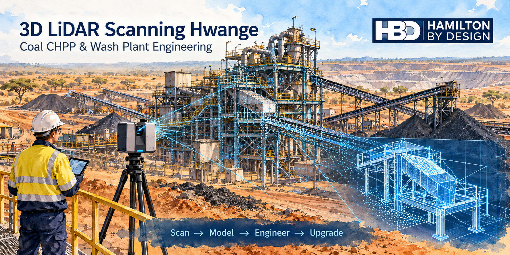
3D LiDAR Scanning for Coal CHPPs and Wash Plants in Hwange Zimbabwe

Watercolour illustration of LiDAR scanning at a Hwange coal wash plant, showing conveyors, a tripod scanner, point cloud data and the Hamilton By Design logo.
Blue line icon of a tripod-mounted LiDAR scanner surveying a mineral processing plant with a hopper, conveyors and transfer chute.

Hamilton By Design offers engineering-led 3D LiDAR scanning and scan-to-CAD support for coal handling and preparation plant projects in Hwange, northwest Zimbabwe. We help mining operators, maintenance teams and project engineers capture existing plant layouts and develop mechanical modifications around actual site conditions.

Whether the project involves a replacement transfer chute, conveyor modification or coal wash plant upgrade, reliable measurements provide a stronger starting point for design and fabrication. Our approach connects site capture with 3D modelling, mechanical engineering and practical drawing deliverables.

Zimbabwe projects are assessed individually, with site scanning arrangements, mobilisation, access requirements and remote engineering support agreed during project scoping.

Coal Handling and Wash Plant Engineering in Hwange

Hwange is an established coal mining and processing centre. Coal operations in the region include run-of-mine crushing, conveyor transport, washing and product handling. Makomo Resources, for example, describes coal washing using dense medium separation, magnetic separation and spiral separation.

Coal handling and preparation plants depend on interconnected equipment. A modification to one chute, screen or pump arrangement can affect surrounding pipework, support frames, access platforms and maintenance space.

For existing facilities, the challenge is often understanding how replacement equipment will fit into a plant that has changed over many years. Original drawings may show the initial installation while overlooking later repairs, equipment replacements and site modifications.

3D LiDAR scanning creates a current dimensional reference for planning these upgrades.

Why Scan a Coal Plant Before Modifying It?

Traditional measurements can capture individual dimensions, but complex plant upgrades require an understanding of the relationships between equipment.

A replacement chute may need to connect to an existing screen outlet, clear a support beam, discharge onto a conveyor and remain accessible for maintenance. Measuring each feature separately can leave gaps in the information needed for design.

3D laser scanning captures visible surfaces as a point cloud. Multiple scan positions are registered into a coordinated dataset, allowing designers to examine equipment positions, elevations and available space.

For a Hwange CHPP or wash plant project, scanning can help teams:

  • Establish existing conveyor and transfer point geometry.
  • Identify the space available for replacement equipment.
  • Check proposed layouts against surrounding plant.
  • Plan pipe routes and maintenance access.
  • Prepare drawings using current site information.
  • Reduce repeat visits for measurements already captured.

The scanning scope should reflect the engineering task. A targeted survey of a transfer station or pump area may provide the information required without scanning the entire facility.

LiDAR Scanning for Coal Conveyors and Transfer Chutes

Coal transfer points bring together conveyor discharge geometry, receiving belts, chutes, support frames and access systems. Differences between drawings and installed equipment can complicate replacement work.

Scanning can capture the visible geometry around conveyor head pulleys, chute exteriors, hoppers, guards, support members and adjacent platforms. This information provides a reference for modelling replacement components and checking their installation clearances.

Hamilton By Design can support:

  • Replacement transfer chute layouts.
  • Conveyor discharge and receiving interfaces.
  • Hopper and feed chute modifications.
  • Wear liner arrangements.
  • Mechanical connection details.
  • Fabrication and assembly drawings.
  • Maintenance access reviews.

Chute performance also depends on coal properties, moisture, particle size distribution, belt speed and throughput. Scan data establishes the available geometry, while operating information guides the design.

Internal chute surfaces require suitable access. Scanning the exterior does not reveal concealed liners, plate thickness or material build-up inside an enclosed chute.

Scanning Coal Wash Plant Equipment

Wash plant upgrades often involve congested layouts with equipment positioned across several levels. Floors, beams, pipe racks and existing maintenance arrangements can restrict the space available for new equipment.

A scanning scope can include accessible areas around:

  • Feed and distribution arrangements.
  • Screens and dewatering equipment.
  • Dense medium cyclones and associated pipework.
  • Sumps, pump boxes and slurry pumps.
  • Product and reject conveyors.
  • Process water systems.
  • Pipe racks and equipment supports.
  • Platforms, stairs and maintenance access.

Before scanning, we identify the equipment interfaces that need measurement and whether components must be isolated, cleaned or opened.

Dust, water spray, moving equipment and obstructed sightlines can affect capture quality. Planning suitable scan positions helps improve coverage and identify where supplementary measurements are required.

Scan to CAD for Existing CHPP Upgrades

A point cloud provides a dimensional reference. A CAD model converts selected information into geometry that can be used for design, coordination and drawings.

Hamilton By Design develops models using SolidWorks and AutoCAD, with deliverables selected to suit the clientโ€™s project and software requirements.

Modelling can focus on the equipment being changed and the surrounding features needed to check its fit. For example, replacing a screen discharge chute may require the screen outlet, chute envelope, receiving conveyor, support members and maintenance access to be modelled.

An agreed level of detail keeps the work focused. Measured geometry, approximate representations and features requiring additional verification are identified during the modelling process.

Learn more about our 3D laser scanning services.

Mechanical Design and Fabrication Support

Following site capture, the next step is developing a modification that suits the operating plant and can be manufactured and installed.

Hamilton By Design can assist with mechanical design for conveyor interfaces, transfer chutes, hoppers, pump boxes, pipe routing, equipment arrangements and guarding layouts.

Drawing packages can communicate component dimensions, assembly requirements, connection details and installation interfaces. This helps fabrication teams understand how the proposed equipment relates to the existing plant.

Critical features such as bolt hole patterns, flange faces and machined fits may require direct measurement or a separate detailed survey. These requirements are identified according to the fabrication tolerance and intended use.

Structural verification, process design and local certification requirements are defined within the project scope, with appropriately qualified specialists involved where required.

Explore our mechanical engineering consulting and mechanical drafting services.

Prepare for Shutdown Installation

A planned shutdown provides limited time to remove equipment, install replacements and return the plant to service. Capturing existing conditions before the shutdown supports earlier design and fabrication decisions.

A coordinated model can help review:

  • Component delivery and removal routes.
  • Equipment installation clearances.
  • Access for lifting and handling.
  • Interfaces with existing pipework and supports.
  • Temporary obstructions.
  • The proposed installation sequence.

Clash checks can identify geometric conflicts before components arrive on site. This gives the project team an opportunity to adjust the design while changes are easier to manage.

For staged projects, accessible areas may be scanned during operation, followed by additional measurements during isolation. The approach must be coordinated with the siteโ€™s operating conditions and safety procedures.

Deliverables for Hwange Coal Plant Projects

Deliverables are selected around the purpose of the project and may include:

  • Registered 3D point clouds.
  • Existing-condition CAD models.
  • Plant layout and general arrangement drawings.
  • Sections and equipment interface details.
  • Mechanical design models.
  • Fabrication and assembly drawings.
  • PDF review packages.

Point cloud formats can include E57 or RCP. Model exchange formats may include STEP or other agreed CAD formats.

Before work starts, we agree on coordinate references, model detail, file formats, revision requirements and dimensional acceptance criteria.

For clients with existing scan data, Hamilton By Design can assess whether the dataset is suitable for remote modelling and mechanical design. Registration quality, coverage and critical interfaces need review before the information is relied on.

Frequently Asked Questions

What does CHPP mean?

CHPP stands for coal handling and preparation plant. It generally covers activities such as coal crushing, sizing, washing and product handling. The equipment and process configuration vary between facilities.

Can LiDAR scanning be completed while a wash plant is operating?

Some accessible areas may be scanned during operation, subject to site approval and conditions. Moving equipment, dust and water spray can affect capture quality. Scanning inside enclosed equipment or hazardous areas may require isolation and specific access arrangements.

Can scanning help with replacement coal chutes?

Yes. Scanning establishes the visible geometry around a chute and its connections, supporting replacement design and fit checks. Internal surfaces and critical fabrication interfaces may need additional measurements.

Does scanning confirm equipment condition or structural capacity?

A scan records visible surface geometry. Plate thickness, material properties, weld integrity and load capacity require appropriate inspection and engineering assessment.

What scanning accuracy should we specify?

Accuracy should match the intended use. Plant layout coordination and precision component fabrication have different requirements. Project tolerances and verification methods should be agreed before scanning begins.

Can Hamilton By Design use scans supplied by a Zimbabwean survey company?

Yes, subject to a review of the dataset. We can assess registration, coordinates, coverage and suitability for the proposed modelling or design scope. Additional measurements may be required where interfaces are missing or insufficiently resolved.

Can Hamilton By Design support projects in Hwange?

We welcome enquiries for Hwange coal handling and wash plant projects. Site capture, international mobilisation, local coordination and remote design arrangements are assessed against the scope, schedule and access requirements.

Discuss Your Hwange Coal Plant Project

Planning a conveyor modification, replacement chute or coal wash plant upgrade in Hwange?

Send Hamilton By Design the plant location, equipment photographs, available drawings and a short description of the proposed work. Include the shutdown date, required deliverables and any existing point cloud data.

We can then define a practical scope for scanning, modelling and mechanical design.

Contact Hamilton By Design to discuss your Hwange CHPP or coal wash plant project.


Hamilton By Design logo displayed on a blue tilted rectangle with a grey gradient background

Contact Us – Talk To Us

Name
Would you like us to arrange a phone consultation for you?
Address

Our clients:


Chute Design Limeira, Sรฃo Paulo โ€” Consistent Material Flow and Reduced Wear

Hamilton By Design illustration of LiDAR scanning and a cutaway mineral processing chute, showing ore flow and wear liners for chute design in Limeira, Sรฃo Paulo.

Consistent material flow, reduced wear and practical maintenance

Blue line icon of a tripod-mounted LiDAR scanner surveying a mineral processing plant with a hopper, conveyors and transfer chute.

Transfer chutes connect critical stages of a mineral processing plant. From crusher discharge to screen feed and conveyor transfers, their design influences how reliably material moves through the operation.

Poorly matched chute geometry can contribute to blockages, spillage, uneven equipment loading and premature liner wear. These problems can increase maintenance demands and interrupt production.

Hamilton By Design offers mechanical design support for mineral processing equipment manufacturers, mining suppliers, fabrication workshops and plant operators in Limeira, Sรฃo Paulo, and businesses serving mining projects throughout Brazil.

Drawing on Australian mining and materials handling experience, we develop chute designs that bring together material flow, wear protection, equipment interfaces and fabrication requirements.

Planning a new transfer chute or upgrading an existing installation? Discuss your project with Hamilton By Design.

Chute design for mineral processing applications

Each transfer point has a specific purpose within the processing circuit. A chute feeding a screen requires a different approach from one receiving coarse material discharged by a crusher.

Our design support can cover:

  • Conveyor-to-conveyor transfer chutes.
  • Crusher feed and discharge chutes.
  • Screen feed, discharge and product collection chutes.
  • Transfer arrangements for ore, crushed rock and mineral products.
  • Chute modifications associated with plant upgrades.
  • Replacement chute bodies and wear liner systems.

We consider how the chute receives material, controls its path and delivers it to the next item of equipment.

The objective is reliable transfer across the agreed operating range, with a design that fits the plant and supports practical maintenance.

Understand the material before developing the geometry

Mineral processing chutes must accommodate the characteristics of the material passing through them.

Coarse particles, abrasive rock, wet fines and variable feed conditions can create different flow and wear challenges. Understanding these conditions helps establish suitable chute geometry and wear protection.

Our design process considers:

  • Material type, bulk density and particle size distribution.
  • Maximum lump size and the proportion of fines.
  • Moisture content and potential for adhesion or build-up.
  • Normal, peak and variable throughput.
  • Conveyor speed and material discharge trajectory.
  • Transfer height and changes in flow direction.
  • Receiving belt, crusher or screen requirements.
  • Existing blockages, wear patterns and maintenance records.

Where necessary, material testing or additional operating data can be included in the scope to resolve uncertainties before detailed design.

Control the flow and reduce concentrated wear

Wear protection begins with understanding how material moves through the chute.

Impact at entry points, abrupt changes in direction and concentrated sliding contact can place heavy demands on chute surfaces. We review these areas alongside the liner arrangement.

Depending on the application, the design may incorporate:

  • Geometry that guides the material through the transfer.
  • Replaceable liners selected for the expected abrasion and impact.
  • Localised protection at high-wear areas.
  • Material-retaining features where suitable for the feed conditions.
  • Modular liner sections for practical replacement.

Wear-resistant steel, rubber, polyurethane and ceramic systems each have different application requirements. Selection should reflect the material, impact conditions, attachment method and maintenance strategy.

Our aim is to reduce avoidable wear and improve serviceability. Expected liner life depends on the operating conditions and selected system.

Assess proposed designs with particle-flow simulation

For complex transfers or recurring flow problems, Discrete Element Methodโ€”DEMโ€”analysis can be included in the project scope.

DEM can help assess material trajectories, accumulation, discharge behaviour and interaction with chute surfaces. It can also support comparison of alternative geometries before fabrication.

Representative material properties and appropriate calibration are essential to obtaining useful results. Simulation findings should be assessed alongside site observations, engineering judgement and operating data.

From existing plant to fabrication-ready documentation

Plant upgrades often require new equipment to fit within existing steelwork, conveyors and restricted installation spaces.

Hamilton By Design can work from drawings, photographs, verified measurements and suitable point cloud data to develop the chute and its interfaces.

Where 3D scanning is required, capture arrangements and responsibilities can be agreed as part of the scope.

Deliverables can include:

  • Existing equipment and interface models.
  • Concept designs and option reviews.
  • Detailed 3D chute models.
  • General arrangement drawings.
  • Fabrication drawings and component details.
  • Wear liner layouts and replacement details.
  • Coordination with client engineers and fabrication teams.

The agreed documentation supports manufacture, installation and future maintenance.

Design for inspection and liner replacement

A chute should be accessible to the people responsible for keeping it operational.

We consider inspection openings, liner handling, fastener access, lifting provisions and installation clearances. Where applicable, the scope can also address guarding and isolation interfaces with surrounding equipment.

Maintenance requirements should be established early so that access and replacement tasks are considered alongside material flow.

For Brazilian projects, applicable local requirements and approval responsibilities are agreed with the client and their local engineering team.

Australian mining experience, working with Limeiraโ€™s industry

Hamilton By Design welcomes opportunities to collaborate with equipment manufacturers, engineering teams and fabrication businesses in Limeira.

We bring Australian mining and materials handling experience, supported by mechanical design, 3D modelling and scan-to-CAD capabilities. Local partners bring knowledge of their equipment, operating conditions and manufacturing requirements.

Our Portuguese is still a work in progress, so we place particular importance on clear drawings, agreed terminology and documented design reviews.

And we already appreciate a good Brazilian start to the morning: pรฃo de queijo and cafรฉ.

Frequently asked questions

Can you redesign a chute that repeatedly blocks?

Yes. We can assess the existing geometry, material characteristics and operating conditions to develop improvement options. Details of when blockages occurโ€”including changes in moisture or throughputโ€”help identify the likely causes.

Can you design chutes for abrasive ore and crushed rock?

Yes. The scope can address chute geometry, impact zones, liner selection and replacement arrangements. Material characteristics and operating data are needed to develop a suitable design.

Can you use an existing plant scan?

Yes. Suitable point cloud data can help establish equipment interfaces and available space. Critical dimensions and areas obscured during scanning may require additional verification.

Can you guarantee a specific liner life?

A liner-life commitment requires supporting evidence about the material, throughput and operating conditions. We can develop a wear strategy and document the design assumptions for comparison with operating performance.

Can you work remotely with a manufacturer in Limeira?

Yes. Remote design support can be arranged using agreed drawings, measurements, scan data and review meetings. Site verification, fabrication responsibilities and local approvals are defined within the project scope.

Discuss your mineral processing chute project

Send Hamilton By Design your existing drawings, photographs, material details, throughput requirements and a description of the transfer problem.

Whether you are developing new mineral processing equipment or upgrading a mining installation, we can help establish a practical design scope.

Contact Hamilton By Design to discuss chute design for mineral processing and mining projects in Limeira, Sรฃo Paulo.


Hamilton By Design logo displayed on a blue tilted rectangle with a grey gradient background

Contact Us – Talk To Us

Name
Would you like us to arrange a phone consultation for you?
Address

Our clients: