


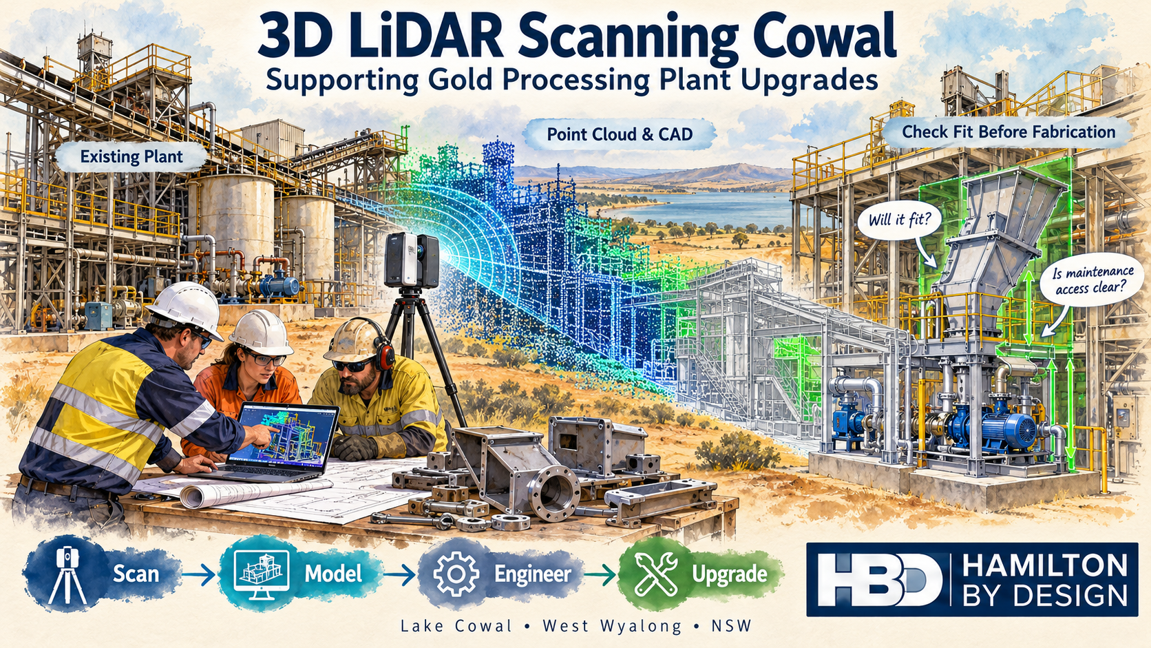

Hamilton By Design offers 3D LiDAR scanning in the Cowal and West Wyalong region to support mechanical engineering, equipment replacement and gold processing plant upgrades. By capturing existing plant geometry before design begins, we help project teams understand available space, assess equipment interfaces and plan modifications with greater confidence.
From a replacement transfer chute to a new pump skid or revised pipe route, reliable information about the existing installation provides a stronger starting point for engineering and fabrication.
Our approach is straightforward: scan → model → engineer → upgrade.
Supporting Gold Processing Projects Near Lake Cowal
Evolution Mining’s Cowal Gold Operations is located near Lake Cowal, approximately 40 kilometres northeast of West Wyalong in New South Wales. The operation includes both open-pit and underground gold mining.
For contractors and engineering teams working on established processing plants, an important challenge is understanding how proposed equipment will fit around the existing installation.
Original drawings provide useful background, but subsequent modifications may have changed pipe routes, equipment positions, access platforms and support arrangements. A new component designed from incomplete information can encounter unexpected clashes during installation.
Hamilton By Design provides scanning and mechanical design services that can support projects in this region, helping teams establish existing conditions before committing to fabrication.
Why Scan Before Designing a Plant Upgrade?
A processing plant upgrade involves more than finding space for a new machine. The design also needs to consider its connections, surrounding equipment, installation route and future maintenance access.
3D LiDAR scanning captures visible surfaces as a point cloud. This creates a spatial record that can be reviewed, measured and used as a reference within compatible CAD software.
Depending on the agreed scope and site access, scanning can help establish:
- Existing equipment positions and surrounding geometry.
- Conveyor and transfer chute interfaces.
- Pipe routes and accessible connection locations.
- Platform, stair and walkway arrangements.
- Visible steelwork and support locations.
- Space around pumps, tanks and mechanical equipment.
- Potential clashes between proposed and existing installations.
- Clearances for maintenance and component removal.
Capturing these details early helps the design team identify questions while there is still time to resolve them.
Checking Component Fit Before Fabrication
One of the most useful applications of 3D LiDAR scanning Cowal is checking proposed components against the existing plant.
For example, a replacement chute may need to connect to an existing conveyor discharge, pass through a platform opening and avoid nearby pipework. Each interface affects the final design.
Using a registered point cloud, Hamilton By Design can develop a CAD model of the relevant area and position the proposed component within it.
This allows the project team to review questions such as:
- Does the component fit within the available space?
- Do its inlet and outlet positions suit the existing equipment?
- Are there clashes with steelwork, pipes or platforms?
- Can personnel reach inspection and maintenance points?
- Is there enough room to remove liners, motors or other serviceable parts?
- Does installation require temporary removal of surrounding equipment?
Checking fit in the model helps reduce uncertainty before steel is cut and equipment arrives on site.
Critical interfaces still need an agreed measurement and verification approach, particularly where tight tolerances apply.
Conveyor and Transfer Chute Modifications
Conveyors and transfer chutes bring together several mechanical interfaces within a relatively small area.
A modification may need to accommodate existing conveyor geometry, support steelwork, liner arrangements, access doors and nearby services. Measuring each feature separately can make it difficult to understand their relationship.
3D scanning provides a common spatial reference for reviewing the installation.
Hamilton By Design can use scan data to support:
- Replacement transfer chute layouts.
- Conveyor discharge and receiving interfaces.
- Chute relocation and connection geometry.
- Wear liner and access door arrangements.
- Guarding layouts.
- Maintenance access reviews.
- General arrangement and fabrication drawings.
The point cloud establishes the visible geometry. Mechanical design then considers operating requirements, material characteristics and the intended function of the equipment.
Pump Skids, Pipework and Equipment Replacement
Replacing a pump or installing a new skid can affect more than its immediate footprint.
Suction and discharge connections, surrounding pipework, motor access, lifting arrangements and maintenance space all influence the layout.
A scan of the installation area can help the design team assess these relationships before selecting a final arrangement.
Typical applications include:
- Positioning replacement pump skids.
- Reviewing accessible pipe connection locations.
- Developing preliminary pipe routes.
- Checking equipment footprints.
- Assessing space for valves and maintenance tasks.
- Identifying clashes with existing services.
- Preparing coordinated mechanical layouts.
Where flange faces, bolt patterns or other connection details are critical, additional measurements may be required. The capture method should match the tolerance needed for the job.
Scan-to-CAD for Gold Processing Plant Upgrades
A point cloud is a valuable reference, but many projects also need a practical CAD model.
Hamilton By Design can convert selected scan geometry into a model suitable for the agreed design task. This may involve modelling an equipment installation, a transfer area or the surrounding plant layout.
The level of detail should reflect the project’s purpose.
A preliminary layout may only need equipment envelopes and major obstacles. A replacement component may require more detailed modelling of its connection points and surrounding interfaces.
Depending on the scope, deliverables can include:
- Registered point clouds in agreed formats, such as E57 or RCP.
- Selected existing-condition CAD models.
- Proposed mechanical equipment models.
- General arrangement drawings.
- Fabrication drawings for agreed components.
- STEP, DXF or other compatible CAD files.
- PDF drawing packs for review and coordination.
Agreeing on the intended use of the data at the start helps ensure that scanning and modelling capture the information the project actually needs.
Planning Work Around Shutdowns
Shutdown installation periods place pressure on maintenance teams, fabricators and contractors. Discovering an unexpected clash during that window can lead to urgent modifications and additional work.
Scanning ahead of a shutdown gives the project team an opportunity to review the installation while design changes are still manageable.
A coordinated model can help teams assess:
- Component delivery and installation routes.
- Available space for assembly.
- Nearby equipment that may restrict access.
- Interfaces requiring confirmation.
- Temporary removal requirements.
- The proposed installation sequence.
Scanning access must be coordinated with site personnel. Equipment isolation, permits, elevated access and operating conditions may affect what can be captured and when.
Early planning helps establish a realistic scope and identify areas that require a separate visit or shutdown access.
Matching Accuracy to the Engineering Task
Different engineering tasks require different levels of measurement detail.
Plant layout scanning can provide a useful record of equipment positions and surrounding geometry. Small machined features, bolt holes and precision mating surfaces may require closer inspection, direct measurement or a suitable metrology scanning method.
For each project, Hamilton By Design considers:
- The dimensions that matter to the design.
- The required fit and tolerance.
- Scanner access and viewing angles.
- Surface conditions and visibility.
- Registration requirements.
- Features requiring supplementary measurement.
LiDAR captures visible surfaces. Hidden connections, internal geometry and obscured areas need further investigation where they affect the design.
The aim is to provide information suitable for the engineering decision being made.
A Practical Workflow from Site Capture to Drawings
Hamilton By Design combines scanning with mechanical engineering and drafting support.
Our workflow starts by defining the proposed modification and identifying its critical interfaces. We then plan the site capture, register the scan data and develop the models needed for review.
Once the proposed arrangement has been assessed and key details confirmed, drawings can be prepared for the agreed fabrication or installation scope.
This connects the site information to a practical outcome: a better-informed design, clearer drawings and fewer unresolved fit-up questions.
Frequently Asked Questions
Can 3D LiDAR scanning help check whether new equipment will fit?
Yes. Scan data can be used as a reference for positioning proposed equipment and checking surrounding clearances. Critical dimensions and interfaces should be verified to suit the required tolerance.
Can you develop fabrication drawings from scan data?
Yes. Hamilton By Design can develop selected CAD models and fabrication drawings from suitable scan data, subject to the agreed scope and confirmation of critical details.
Does the entire processing plant need to be scanned?
No. A targeted scan may be sufficient for a replacement chute, pump installation or local pipework modification. Wider capture can be useful where the project involves several connected areas.
Can scanning take place while the plant is operating?
Some areas may be accessible during operation, subject to site approval and safe access. Other areas may require isolation or shutdown access to capture the necessary geometry.
Can you work with existing point clouds?
Yes. Supplied point clouds can be reviewed for coverage, registration quality and suitability. Additional scanning or measurement may be needed where important interfaces are missing or unclear.
Discuss Your Cowal Plant Upgrade
Planning an equipment replacement, conveyor modification, transfer chute upgrade or pipework installation near Cowal or West Wyalong?
Hamilton By Design can help establish the existing geometry and develop the mechanical models and drawings needed to progress the project.
Send us an outline of the proposed work, site photographs and any available drawings or point cloud data. We can then assess the capture requirements and recommend an appropriate scope.
Contact Hamilton By Design to discuss 3D LiDAR scanning, scan-to-CAD and mechanical engineering support for your Cowal project.

Contact Us – Talk To Us
Our clients:
























