Systems Engineering, Hazard Identification and Mining Safety

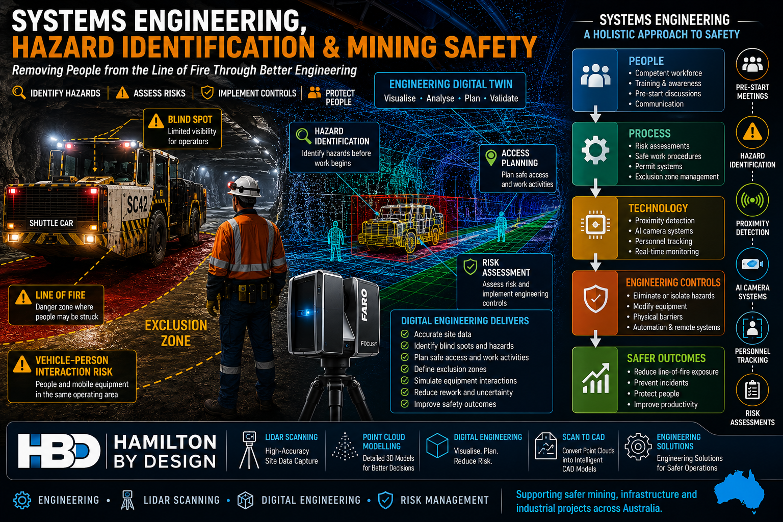
Systems engineering and mining safety infographic showing an underground shuttle car, exclusion zones, hazard identification, engineering digital twin, LiDAR scanning, risk assessment and engineering controls used to reduce line-of-fire risks and improve workplace safety in mining operations.

Lessons from a Preventable Underground Coal Mine Incident

The Technology Exists โ€“ So Why Are We Still Seeing These Incidents?

A recent Resources Safety & Health Queensland (RSHQ) investigation into a near-fatal underground coal mining incident has once again highlighted a challenge that continues to confront the mining industry.

The incident occurred at an underground coal mine near Emerald in Queensland’s Bowen Basin when a worker entered the blind spot of a shuttle car and was struck by the machine. Investigators identified several contributing factors including poor visibility, inadequate communication, high background noise, blind spots around mobile equipment and the absence of proximity detection technology. RSHQ described the event as entirely preventable and encouraged operators to consider technologies already being used successfully at other Queensland mines.

While incidents such as this are often discussed from an operational perspective, they also highlight a broader engineering challenge.

The real question is:

How do we design systems that prevent workers from being exposed to hazards in the first place?

This is where systems engineering becomes critically important.


What is Systems Engineering?

Systems engineering is the disciplined approach of understanding how people, equipment, processes, technology, procedures and the operating environment interact as a complete system.

Rather than focusing on individual components, systems engineering examines:

  • Human factors
  • Equipment design
  • Communication systems
  • Work procedures
  • Environmental conditions
  • Technology controls
  • Organisational culture
  • Training and competency
  • Risk management processes

When a serious incident occurs, it is rarely caused by a single failure.

Instead, multiple weaknesses align simultaneously.

In the Emerald incident, the shuttle car itself was not necessarily defective.

The system failed because:

  • Workers changed position without positive communication.
  • The vehicle operator was unaware of the workers’ location.
  • Visibility was limited.
  • Background noise masked movement.
  • No proximity detection technology was available.
  • Workers entered a line-of-fire zone.

A systems engineering approach asks:

What combination of controls could have prevented the event regardless of human error?


The Hierarchy of Controls

One of the most important principles in safety engineering is the Hierarchy of Controls.

Controls are generally ranked from most effective to least effective:

  1. Elimination
  2. Substitution
  3. Engineering Controls
  4. Administrative Controls
  5. Personal Protective Equipment

Many organisations rely heavily on procedures, training and pre-start discussions.

While these are important, they sit relatively low in the hierarchy.

Engineering controls are often more reliable because they do not depend entirely on human behaviour.

Examples include:

  • Proximity detection systems
  • AI camera systems
  • Collision avoidance systems
  • Personnel tracking systems
  • Physical barriers
  • Interlocks
  • Remote operation technology
  • Autonomous equipment

The objective should always be to engineer hazards out of the system wherever practical.


Hazard Identification Starts Before Work Begins

One of the most effective safety tools available is proactive hazard identification.

Many incidents occur because hazards are recognised only after work has commenced.

Hazard identification should occur during:

Project Planning

Before construction or maintenance work begins.

Design Reviews

Before equipment is fabricated or modified.

Shutdown Planning

Before personnel enter operational areas.

Pre-Start Meetings

Before workers commence each shift.

Field Risk Assessments

Immediately before performing a task.

A robust hazard identification process considers:

  • Mobile equipment interactions
  • Blind spots
  • Stored energy
  • Working at heights
  • Falling objects
  • Confined spaces
  • Vehicle movements
  • Emergency access
  • Simultaneous operations
  • Human factors

The goal is simple:

Identify hazards before they have an opportunity to cause harm.


Why Pre-Start Meetings Matter

In many operations, pre-start meetings can become routine.

Unfortunately, routine often leads to complacency.

The most effective pre-start meetings are not simply administrative exercises.

They provide an opportunity to discuss:

What Has Changed?

  • New equipment
  • New personnel
  • Different environmental conditions
  • Weather impacts
  • Operational changes

What Are Today’s Hazards?

  • Vehicle interactions
  • Exclusion zones
  • Ground conditions
  • Overhead hazards
  • Isolation requirements

What Are the Critical Controls?

  • Spotters
  • Communication methods
  • Isolation procedures
  • Permit requirements
  • Emergency response arrangements

What Could Go Wrong?

This question alone can significantly improve hazard awareness.

A quality pre-start discussion encourages workers to actively think about risk before entering the workplace.


Line-of-Fire Hazards Remain a Major Industry Risk

Across mining, construction, manufacturing and heavy industry, line-of-fire incidents continue to be one of the leading causes of serious injury and fatalities.

Line-of-fire hazards include situations where workers are exposed to:

  • Moving vehicles
  • Rotating equipment
  • Suspended loads
  • Stored energy
  • Pressurised systems
  • Falling objects
  • Uncontrolled equipment movement

Recent Queensland mining safety alerts have repeatedly highlighted similar themes:

  • Workers trapped between vehicles.
  • Workers entering exclusion zones.
  • Poor communication.
  • Lack of positive isolation.
  • Mobile equipment interactions.

The underlying hazards are often well understood.

The challenge is ensuring controls remain effective in real-world operating environments.


The Role of Digital Engineering and LiDAR Scanning

Modern engineering tools are creating new opportunities to identify and manage risk before work begins.

Engineering-grade LiDAR scanning and digital engineering workflows allow project teams to create accurate digital representations of operational facilities.

Applications include:

Access Planning

Identifying safe access routes.

Equipment Interaction Analysis

Assessing vehicle and personnel separation.

Shutdown Planning

Visualising work fronts before crews arrive onsite.

Clash Detection

Identifying conflicts before installation.

Exclusion Zone Development

Understanding hazardous interaction areas.

Emergency Planning

Reviewing evacuation routes and emergency access.

Hamilton By Design regularly supports projects through:

  • Engineering-grade LiDAR scanning
  • Point cloud modelling
  • Scan-to-CAD workflows
  • Digital engineering
  • Mechanical engineering
  • Brownfield modifications
  • As-built documentation

These tools provide project teams with accurate information that can improve both productivity and safety outcomes.


Proximity Detection Technology is Not New

One of the most significant observations from the recent incident is that proximity detection technology already exists.

In fact, underground mining industries have been investigating and deploying proximity detection systems around continuous miners and shuttle cars for many years. These systems can identify personnel entering predefined warning or hazard zones and initiate alarms, slowdowns or machine intervention depending on the system design.

Modern systems can provide:

  • Warning zones
  • Slow-down zones
  • Automatic stop functions
  • Personnel tracking
  • Vehicle interaction monitoring
  • AI-assisted hazard detection

The question is no longer whether the technology is available.

The question is how quickly and consistently industry adopts it.


Building Safer Systems

A mature safety culture understands that procedures alone are rarely enough.

The strongest organisations focus on building multiple layers of protection.

This includes:

People

  • Training
  • Competency
  • Communication

Processes

  • Risk assessments
  • Safe work procedures
  • Permit systems

Technology

  • Proximity detection
  • AI vision systems
  • Personnel tracking

Engineering

  • Equipment redesign
  • Physical barriers
  • Elimination of hazards

Leadership

  • Safety culture
  • Accountability
  • Continuous improvement

When these elements work together, the likelihood of serious incidents is dramatically reduced.


Final Thoughts

The recent underground coal mining incident serves as a powerful reminder that safety is fundamentally a systems engineering challenge.

The objective should not simply be to react to incidents.

The objective should be to design work environments where incidents are far less likely to occur.

Hazard identification, risk assessment, effective pre-start meetings, engineering controls and modern technologies all play a critical role in achieving this outcome.

As the mining industry continues to embrace digital engineering, LiDAR scanning, automation, AI systems and proximity detection technologies, there is a significant opportunity to remove people from the line of fire and create safer workplaces.

The technology exists.

The challenge is ensuring it is implemented before the next near miss becomes a fatality.


Hamilton By Design logo displayed on a blue tilted rectangle with a grey gradient background

References

  1. Resources Safety & Health Queensland (RSHQ) โ€“ Safety Alert: Underground shuttle car incident.
  2. Resources Safety & Health Queensland (RSHQ) โ€“ Vehicle interaction and line-of-fire safety alerts.
  3. Proximity Detection Systems in Underground Mines โ€“ Queensland Mining Industry Health and Safety Conference.
  4. Proximity Detection Options on Underground Mining Equipment.
  5. Safe to Work โ€“ Coal mine collision highlights parking procedure risks.

Contact Us – Talk to Us

Name
Would you like us to arrange a phone consultation for you?
Address
Australian Drafting logo featuring bold white text reading "Australian Drafting" centred on a blue rounded rectangle background.
Engineering Governance title graphic featuring bold white text reading "Engineering Governance" centred on a blue rounded rectangle background.
Mechanical, Structural & Pipework Drafting service banner by Hamilton By Design featuring white text on a blue background.
Mechanical engineering services
Blue rounded button with the text โ€œSolidWorks Designโ€ in white.
Finite Element Analysis (FEA) engineering simulation button
3D LiDAR Scanning Darwin for engineering surveys, laser scanning, reality capture and point cloud modelling services
3D LiDAR Scanning Australia engineering services for laser scanning, reality capture, scan-to-CAD, Scan-to-BIM and as-built documentation across Australia
3D LiDAR scanning services on the Central Coast providing engineering-grade laser scanning, point cloud capture, scan-to-CAD modelling and industrial reality capture for infrastructure and industrial projects.
3D LiDAR Scanning Perth for engineering surveys, laser scanning, reality capture and point cloud modelling services
3D LiDAR Scanning Sydney for engineering surveys, laser scanning, reality capture and point cloud modelling services
3D LiDAR Scanning Brisbane for engineering surveys, laser scanning, reality capture and point cloud modelling services
3D LiDAR Scanning Canberra for engineering surveys, laser scanning, reality capture and point cloud modelling services
3D LiDAR Scanning Newcastle for engineering surveys, laser scanning, reality capture and point cloud modelling services
3D LiDAR Scanning Adelaide for engineering surveys, laser scanning, reality capture and point cloud modelling services

Project Management Challenges

Hamilton By Design project management infographic showing how engineering-grade LiDAR scanning, reality capture, mechanical engineering, CAD modelling, and project controls help overcome common project challenges. The graphic highlights issues such as incomplete site information, outdated drawings, scope creep, budget overruns, rework, schedule delays, and communication breakdowns. It illustrates a workflow from LiDAR scanning and point cloud data through CAD modelling, verification, and successful project delivery with improved safety, reduced risk, cost certainty, and accurate engineering outcomes.

How the Right Information, 3D Scanning and Engineering Tools Drive Project Success

Your Success Is Our Success

Every project manager starts with the same objective:

Deliver a successful project safely, on time and within budget.

Whether the project involves a mining operation, manufacturing facility, port infrastructure, processing plant, water treatment facility, conveyor system, structural upgrade or equipment installation, success ultimately depends on the quality of the decisions made throughout the project lifecycle.

Unfortunately, project managers often face significant challenges:

  • Inaccurate drawings
  • Unknown site conditions
  • Scope creep
  • Communication issues
  • Budget pressures
  • Schedule constraints
  • Construction clashes
  • Fabrication errors
  • Asset documentation gaps

These challenges rarely occur because people are not trying hard enough.

Most occur because project teams are making decisions with incomplete or inaccurate information.

At Hamilton By Design, we believe project success starts with good information.

That is why we have invested in engineering-grade 3D scanning technologies, digital engineering workflows, CAD platforms, simulation tools and practical engineering expertise to help our clients reduce risk and improve project outcomes.

Your success is our success.

Learn more:


Why Projects Struggle

Project managers are expected to coordinate:

  • Asset owners
  • Operations personnel
  • Engineers
  • Contractors
  • Fabricators
  • Suppliers
  • Maintenance teams
  • Construction crews

Each stakeholder brings different priorities.

Without accurate information, even simple projects can become difficult.

Common issues include:

Drawings Do Not Match Reality

Many industrial facilities have been operating for decades.

Over time:

  • Pipework is modified
  • Equipment is replaced
  • Structures are altered
  • Temporary solutions become permanent

Unfortunately, documentation is not always updated.

Project teams may begin engineering work based on drawings that no longer represent the actual facility.

Site Conditions Are Unknown

A pipe hidden behind equipment.

An undocumented support structure.

An access issue not identified during planning.

Small surprises often become large project delays.

Rework Becomes Expensive

The cost of identifying an issue during design is significantly lower than discovering the same issue during construction.

Good information reduces rework.


The Foundation of Project Success: Accurate Information

Before discussing tools, it is important to understand a simple principle:

Every engineering decision is only as good as the information available.

Accurate information improves:

  • Planning
  • Design
  • Budgeting
  • Scheduling
  • Procurement
  • Construction

This is why modern project delivery increasingly relies on reality capture and digital engineering workflows.


Understanding 3D Scanning Technologies

Not all scanners are the same.

Different technologies suit different applications.

Selecting the correct technology is critical.


Terrestrial LiDAR Scanners

Terrestrial LiDAR scanners are commonly used for industrial facilities.

Examples include:

  • FARO Focus Series
  • Leica RTC360
  • Trimble X9

Typical applications:

  • Processing plants
  • Manufacturing facilities
  • Structural steel
  • Pipework
  • Conveyor systems
  • Buildings

Typical accuracy:

  • ยฑ1 mm to ยฑ3 mm single scan
  • ยฑ2 mm to ยฑ10 mm registered project accuracy

Benefits:

  • Accurate site verification
  • Reduced site visits
  • Improved design confidence

Hamilton By Design uses engineering-grade terrestrial LiDAR scanning to support scan-to-CAD workflows and project delivery.


Mobile LiDAR Systems

Mobile LiDAR systems allow operators to walk through facilities while collecting data.

Examples include:

  • FARO Orbis
  • NavVis VLX
  • Leica BLK2GO

Applications:

  • Warehouses
  • Large buildings
  • Facility documentation

Benefits:

  • Rapid data capture
  • Reduced field time

Limitations:

  • Lower accuracy than tripod-based systems

Structured Light Scanners

Structured light scanners project patterns onto surfaces and capture highly detailed geometry.

Applications:

  • Reverse engineering
  • Product development
  • Component modelling

Typical accuracy:

  • ยฑ0.02 mm to ยฑ0.10 mm

Portable Metrology Arms

Portable metrology systems are used for precision measurement.

Applications:

  • Machined components
  • Gearboxes
  • Pump components
  • Manufacturing inspection

Typical accuracy:

  • ยฑ0.015 mm to ยฑ0.05 mm

Drone LiDAR Systems

Drone-based systems capture large areas quickly.

Applications:

  • Mining
  • Infrastructure
  • Stockpiles
  • Terrain mapping

Typical accuracy:

  • ยฑ20 mm to ยฑ100 mm

How Hamilton By Design Uses Scanning to Improve Project Outcomes

Scanning alone does not deliver project success.

Success comes from transforming captured data into useful engineering information.

Our workflow includes:

1. Site Verification

Capture existing conditions.

2. Point Cloud Registration

Align scan data accurately.

3. Scan-to-CAD

Convert reality into engineering models.

4. Engineering Design

Develop practical solutions.

5. Design Reviews

Identify issues before fabrication.

6. Drawing Production

Generate clear construction documentation.

7. Construction Support

Assist project teams during delivery.

8. As-Built Verification

Confirm final installation.


Hamilton By Design’s Project Delivery Toolkit

FARO Focus S70

Used for:

  • Industrial facilities
  • Pipework
  • Structural steel
  • Conveyors

Benefits:

  • Accurate existing-condition information
  • Improved project confidence

SOLIDWORKS

Used for:

  • Mechanical design
  • Equipment design
  • Reverse engineering

Benefits:

  • Manufacturing-ready models
  • Parametric design

AutoCAD

Used for:

  • General arrangements
  • Fabrication drawings
  • Construction documentation

FARO SCENE

Used for:

  • Registration
  • Quality control
  • Point cloud management

Autodesk ReCap

Used for:

  • Point cloud processing
  • Scan-to-CAD workflows

Navisworks

Used for:

  • Model reviews
  • Coordination
  • Clash detection

SOLIDWORKS Simulation

Used for:

  • Stress analysis
  • Structural verification

ANSYS

Used for:

  • Advanced engineering analysis

Rocky DEM

Used for:

  • Bulk materials handling
  • Chute design
  • Conveyor systems

The Benefits to Project Managers

When accurate information is available early:

Better Planning

Teams understand site conditions.

Better Budget Control

Unexpected variations are reduced.

Better Communication

Stakeholders review the same information.

Better Constructability

Designs are reviewed before fabrication.

Better Outcomes

Projects progress with greater confidence.


Why Experience Matters

Technology alone does not solve project challenges.

Hamilton By Design combines:

  • Mechanical engineering
  • Drafting
  • Manufacturing experience
  • Site experience
  • Reverse engineering
  • Reality capture
  • Digital engineering

Our objective is not simply to collect scan data.

Our objective is to help clients deliver successful projects.


Hamilton By Design logo displayed on a blue tilted rectangle with a grey gradient background

Contact Us – Talk to Us

Name
Would you like us to arrange a phone consultation for you?
Address

Our Clients

Project success begins with reliable information.

By combining engineering-grade 3D scanning, scan-to-CAD workflows, mechanical engineering, simulation and practical project experience, Hamilton By Design helps project managers reduce uncertainty and improve outcomes.

From reality capture through to engineering design and construction support, our focus remains simple:

Your Success Is Our Success.

Learn more:

www.hamiltonbydesign.com.au

Additional engineering articles:

https://hamiltonbydesign.blogspot.com

Pipework detailing resources:

https://pipeworkdetailing.blogspot.com


Frequently Asked Questions

1. What are the biggest project management challenges?

Schedule delays, budget overruns, scope creep, poor communication and inaccurate information.

2. How does 3D scanning improve project delivery?

It provides accurate site information for planning and design.

3. What scanner does Hamilton By Design use?

The FARO Focus S70 terrestrial LiDAR scanner.

4. What is scan-to-CAD?

The process of converting scan data into engineering models and drawings.

5. How can LiDAR scanning reduce project risk?

By identifying existing conditions before design begins.

6. Can scanning reduce site visits?

Yes.

7. What industries benefit from scanning?

Mining, manufacturing, ports, infrastructure and processing plants.

8. What is a point cloud?

A digital representation of a physical environment.

9. Why is accurate information important?

Because project decisions depend on it.

10. Can scanning reduce rework?

Yes.

(Continue through FAQ 50 covering schedule management, budget control, stakeholder communication, brownfield projects, pipework modelling, structural steel, reverse engineering, shutdown planning, digital twins, clash detection, engineering analysis and project success.)


References

Hamilton By Design

www.hamiltonbydesign.com.au

Hamilton By Design Blog

https://hamiltonbydesign.blogspot.com

Pipework Detailing Blog

https://pipeworkdetailing.blogspot.com

FARO Technologies

https://www.faro.com

SOLIDWORKS

https://www.solidworks.com

ANSYS

https://www.ansys.com

Autodesk ReCap

https://www.autodesk.com/products/recap

Autodesk Navisworks

https://www.autodesk.com/products/navisworks

3D CAD Modelling Australia service banner for Hamilton By Design
Australian Drafting logo featuring bold white text reading "Australian Drafting" centred on a blue rounded rectangle background.
Engineering Governance title graphic featuring bold white text reading "Engineering Governance" centred on a blue rounded rectangle background.
Mechanical, Structural & Pipework Drafting service banner by Hamilton By Design featuring white text on a blue background.
Mechanical engineering services
Blue rounded button with the text โ€œSolidWorks Designโ€ in white.
Finite Element Analysis (FEA) engineering simulation button
3D LiDAR Scanning Darwin for engineering surveys, laser scanning, reality capture and point cloud modelling services
3D LiDAR Scanning Australia engineering services for laser scanning, reality capture, scan-to-CAD, Scan-to-BIM and as-built documentation across Australia
3D LiDAR scanning services on the Central Coast providing engineering-grade laser scanning, point cloud capture, scan-to-CAD modelling and industrial reality capture for infrastructure and industrial projects.
3D LiDAR Scanning Perth for engineering surveys, laser scanning, reality capture and point cloud modelling services
3D LiDAR Scanning Sydney for engineering surveys, laser scanning, reality capture and point cloud modelling services
3D LiDAR Scanning Brisbane for engineering surveys, laser scanning, reality capture and point cloud modelling services
3D LiDAR Scanning Canberra for engineering surveys, laser scanning, reality capture and point cloud modelling services
3D LiDAR Scanning Newcastle for engineering surveys, laser scanning, reality capture and point cloud modelling services
3D LiDAR Scanning Adelaide for engineering surveys, laser scanning, reality capture and point cloud modelling services

FARO Blink Benefits | Faster Reality Capture for Engineering Projects

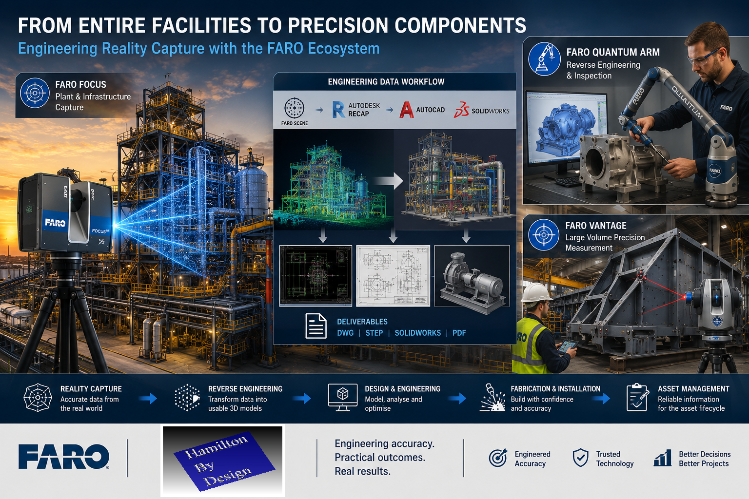
Industrial engineering workflow showing FARO Focus laser scanning of a processing plant, digital Scan-to-CAD modelling, FARO Quantum Arm reverse engineering of a pump housing, and FARO Vantage laser tracker inspection of a fabricated steel structure.

FARO Blink: Making Reality Capture Faster, Simpler and More Accessible

The reality capture industry continues to evolve at an incredible pace.

For many years, 3D laser scanning and LiDAR technologies were considered specialist tools used primarily by surveyors, metrology professionals, and engineering teams with extensive training and experience. While the benefits of reality capture were well understood, the technology often required significant expertise, specialised software, and dedicated workflows to achieve successful outcomes.

Today, that is beginning to change.

The introduction of Blink by FARO represents another significant step toward making reality capture more accessible to a wider range of users. Designed to simplify the process of capturing, managing, and sharing digital site information, Blink demonstrates how automation, cloud connectivity, and intuitive workflows are reshaping the way organisations document and understand their physical assets.

For asset owners, facility managers, project teams, engineers, and contractors, the implications are substantial.

The easier it becomes to capture accurate information about the real world, the easier it becomes to make better decisions.

Why Reality Capture Matters

Before discussing Blink specifically, it is worth understanding why reality capture has become such an important part of modern engineering and asset management.

Many industrial facilities were built decades ago.

Over time they undergo:

  • Plant modifications
  • Equipment upgrades
  • Maintenance projects
  • Structural alterations
  • Utility relocations
  • Expansion works

Unfortunately, documentation does not always keep pace with these changes.

Many facilities operate with:

  • Incomplete drawings
  • Outdated CAD models
  • Missing records
  • Unknown modifications
  • Conflicting documentation

When engineers begin a new project, they often discover that the available information does not accurately reflect existing site conditions.

This creates risk.

Design errors, fabrication clashes, installation delays, and costly rework often result from inaccurate site information.

Reality capture helps solve this problem by creating an accurate digital representation of existing conditions.

Instead of guessing what exists, project teams can work from measured reality.

Blink by FARO has been developed to simplify the process of reality capture by combining laser scanning hardware, automated processing, cloud-based workflows, and digital collaboration tools.

Rather than requiring users to become experts in registration workflows, point cloud processing, and data management, Blink focuses on creating a streamlined experience that allows information to move quickly from site capture to project insights.

The goal is simple:

Capture reality quickly, process it efficiently, and make the information available to the people who need it.

For many organisations this removes some of the barriers that traditionally prevented them from adopting reality capture technology.

Benefit 1: Faster Site Documentation

One of the biggest advantages of modern reality capture systems is speed.

Traditional site measurement often involves:

  • Tape measures
  • Hand sketches
  • Manual notes
  • Laser distance meters
  • Photographs

This approach can be time consuming and often requires multiple visits to site.

When information is missed, the team must return to collect additional measurements.

Reality capture dramatically reduces this risk.

By capturing millions of measured points within the environment, teams create a digital record that can be referenced long after the site visit has been completed.

This means:

  • Fewer return visits
  • Reduced travel costs
  • Faster project commencement
  • Improved confidence in measurements

For remote sites, mines, ports, power stations, and manufacturing facilities, this benefit alone can provide significant value.

Benefit 2: Improved Project Collaboration

Modern projects often involve multiple stakeholders.

These may include:

  • Asset owners
  • Engineers
  • Contractors
  • Draftspersons
  • Project managers
  • Maintenance teams
  • Operations personnel

Historically, communication between these groups relied heavily on drawings, reports, photographs, and site visits.

Reality capture provides a common visual reference that everyone can understand.

Instead of discussing what might exist, project teams can review actual site conditions.

This improves:

  • Communication
  • Decision making
  • Design reviews
  • Stakeholder engagement
  • Project planning

The result is fewer misunderstandings and more efficient project delivery.

Benefit 3: Better Asset Management

Asset owners increasingly recognise the value of maintaining accurate digital records of their facilities.

Reality capture supports:

  • Asset verification
  • Facility documentation
  • Maintenance planning
  • Future upgrades
  • Capital works programs

Rather than relying on historical documentation, organisations can maintain current digital representations of their facilities.

This creates a foundation for long-term asset management and digital engineering initiatives.

Benefit 4: Reduced Project Risk

One of the greatest causes of project cost overruns is unexpected site conditions.

Examples include:

  • Pipework clashes
  • Structural interference
  • Equipment access issues
  • Missing clearances
  • Undocumented modifications

Reality capture helps identify these issues before construction begins.

By working with accurate site information, engineers can identify problems early when they are less expensive to resolve.

This reduces:

  • Rework
  • Variation claims
  • Fabrication errors
  • Installation delays
  • Safety risks

The result is greater project certainty.

Benefit 5: Supporting Digital Transformation

Many organisations are currently pursuing digital transformation initiatives.

These may include:

  • Digital twins
  • Asset management systems
  • BIM environments
  • Digital engineering platforms
  • Smart infrastructure programs

Accurate site information forms the foundation of these initiatives.

Without reliable data, digital transformation becomes difficult to achieve.

Reality capture provides the measured information required to build digital representations of physical assets.

This enables organisations to move toward more connected and data-driven operations.

Benefit 6: Easier Adoption of Reality Capture

Historically, one of the challenges associated with laser scanning has been the level of expertise required.

Specialist operators often needed extensive experience with:

  • Scanning hardware
  • Registration software
  • Point cloud management
  • Data processing
  • Quality control

Automation is helping reduce this complexity.

Systems such as Blink focus on making reality capture easier to deploy and easier to use.

This means more organisations can benefit from digital site documentation without needing to become scanning specialists.

As technology continues to evolve, reality capture is becoming increasingly accessible across industry.

Benefit 7: Enhanced Visualisation

Many people find it easier to understand visual information than technical drawings.

Reality capture provides rich visual context that can support:

  • Design reviews
  • Stakeholder presentations
  • Maintenance planning
  • Safety assessments
  • Operational discussions

Visual access to site information helps project teams communicate more effectively and make decisions with greater confidence.

Benefit 8: Better Information Retention

Facilities change over time.

Personnel change.

Knowledge is lost.

Documentation becomes outdated.

Reality capture creates a permanent digital record of a facility at a specific point in time.

This information can be referenced years later when:

  • Maintenance is required
  • Equipment is replaced
  • Upgrades are planned
  • Incidents are investigated

The value of this historical record often increases over time.

Technology is Only Part of the Solution

While advances such as Blink are making reality capture more accessible, it is important to recognise that technology alone does not solve engineering challenges.

The true value comes from transforming captured information into usable engineering deliverables.

This may include:

  • 3D CAD models
  • General arrangement drawings
  • Fabrication drawings
  • Structural models
  • Mechanical assemblies
  • As-built documentation
  • Asset registers

Collecting data is only the first step.

Engineering expertise remains essential for converting information into practical project outcomes.

Where Hamilton By Design Fits In

At Hamilton By Design, we view reality capture as part of a broader engineering workflow.

Our objective is not simply to capture data.

Our objective is to help clients make better engineering decisions.

We provide:

  • Engineering-grade LiDAR scanning
  • 3D laser scanning
  • Scan-to-CAD services
  • Reverse engineering
  • Mechanical engineering
  • Structural drafting
  • Asset verification
  • Digital engineering support

Our team combines decades of experience in engineering, manufacturing, maintenance, drafting, and industrial project delivery.

This means we understand not only how to collect data, but also how that information is ultimately used within engineering projects.

Learn more about our reality capture services:

From Point Clouds to Engineering Outcomes

One of the biggest misconceptions about reality capture is that the point cloud itself is the final deliverable.

In reality, most organisations require outcomes such as:

  • CAD models
  • Engineering drawings
  • Equipment layouts
  • Structural modifications
  • Fabrication packages
  • Asset documentation

At Hamilton By Design, we routinely transform point cloud data into engineering deliverables that support:

  • Shutdown planning
  • Plant upgrades
  • Equipment replacement
  • Facility expansions
  • Maintenance projects
  • Capital works programs

This is where engineering knowledge and reality capture technology come together.

Looking Ahead

The launch of Blink highlights an important industry trend.

Reality capture is becoming:

  • Faster
  • Simpler
  • More automated
  • More connected
  • More accessible

These developments will continue to expand the adoption of digital site documentation across industry.

For asset owners, facility operators, and project teams, this means better access to accurate information and improved decision making.

For engineering companies, it creates new opportunities to deliver more efficient and more reliable project outcomes.

The future of engineering will increasingly rely on accurate digital representations of the physical world.

Reality capture technologies such as Blink are helping make that future more accessible than ever before.

Explore More

Hamilton By Design supports clients across Australia with engineering-led reality capture and digital engineering services.

Learn more:

Engineering Grade LiDAR Scanning vs Scan-As-You-Walk Systems

Scan to CAD vs Traditional Design Workflows

SolidWorks Point Cloud to CAD Workflow

Automated Object Recognition from Point Clouds

As reality capture technology continues to evolve, organisations that combine accurate data with engineering expertise will be best positioned to deliver safer, smarter, and more successful projects.

Australian Drafting logo featuring bold white text reading "Australian Drafting" centred on a blue rounded rectangle background.
Engineering Governance title graphic featuring bold white text reading "Engineering Governance" centred on a blue rounded rectangle background.
Mechanical, Structural & Pipework Drafting service banner by Hamilton By Design featuring white text on a blue background.
Mechanical engineering services
Blue rounded button with the text โ€œSolidWorks Designโ€ in white.
Finite Element Analysis (FEA) engineering simulation button
3D LiDAR Scanning Darwin for engineering surveys, laser scanning, reality capture and point cloud modelling services
3D LiDAR Scanning Australia engineering services for laser scanning, reality capture, scan-to-CAD, Scan-to-BIM and as-built documentation across Australia
3D LiDAR scanning services on the Central Coast providing engineering-grade laser scanning, point cloud capture, scan-to-CAD modelling and industrial reality capture for infrastructure and industrial projects.
3D LiDAR Scanning Perth for engineering surveys, laser scanning, reality capture and point cloud modelling services
3D LiDAR Scanning Sydney for engineering surveys, laser scanning, reality capture and point cloud modelling services
3D LiDAR Scanning Brisbane for engineering surveys, laser scanning, reality capture and point cloud modelling services
3D LiDAR Scanning Canberra for engineering surveys, laser scanning, reality capture and point cloud modelling services
3D LiDAR Scanning Newcastle for engineering surveys, laser scanning, reality capture and point cloud modelling services
3D LiDAR Scanning Adelaide for engineering surveys, laser scanning, reality capture and point cloud modelling services

Scan-to-CAD vs Traditional Design Workflows | Which Approach Delivers Better Engineering Outcomes?

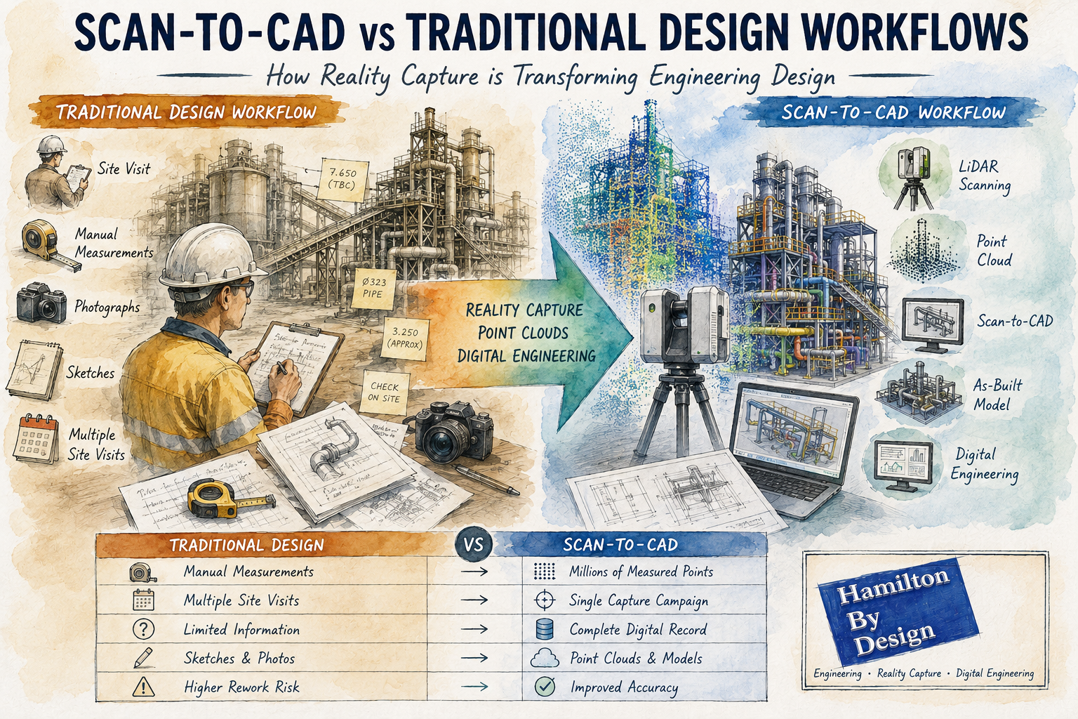
Scan-to-CAD vs traditional design workflows infographic showing LiDAR scanning, point cloud modelling, reality capture and digital engineering for industrial plant design and as-built documentation.

Scan-to-CAD vs Traditional Design Workflows: How Reality Capture is Transforming Engineering Design

For decades, engineering and drafting companies have relied on traditional design workflows to create new assets, modify existing facilities and develop construction documentation. These methods typically involve site visits, manual measurements, photographs, sketches and extensive assumptions about existing conditions.

While traditional design processes have successfully delivered countless projects, modern reality capture technologies are changing how engineering data is collected and utilised.

The introduction of terrestrial LiDAR scanning, engineering-grade reality capture and point cloud modelling has given design companies access to highly accurate representations of existing facilities. Rather than starting with assumptions and limited measurements, engineers can now begin with a digital copy of reality.

This approach is commonly known as Scan-to-CAD.

At Hamilton By Design, we have seen first-hand how Scan-to-CAD workflows can improve project accuracy, reduce site visits and provide better information for engineering decision-making. However, traditional design methods still have an important role to play.

The key is understanding where each approach provides the greatest value.


What is a Traditional Design Workflow?

Traditional design workflows generally begin with a site inspection and manual data collection process.

An engineer, designer or draftsperson visits the facility and records information such as:

  • Dimensions
  • Levels
  • Equipment locations
  • Structural arrangements
  • Pipe routing
  • Building layouts
  • Photographs
  • Sketches

The collected information is then used to develop drawings and 3D models.

A typical workflow may include:

  1. Site visit
  2. Manual measurements
  3. Photographic survey
  4. Sketch preparation
  5. CAD model creation
  6. Design development
  7. Drawing production
  8. Construction issue

This process has been the backbone of engineering design for many years.


Challenges with Traditional Design Methods

Although effective, traditional workflows present several challenges.

Limited Data Collection

No matter how experienced the survey team is, it is impossible to measure everything.

Often only dimensions considered important at the time are collected.

If additional information is required later, another site visit may be necessary.

Human Error

Manual measurements introduce opportunities for error.

Common issues include:

  • Incorrect dimensions
  • Missed measurements
  • Recording errors
  • Inconsistent datum references

These errors can propagate throughout the project.

Access Restrictions

Industrial facilities often contain:

  • Confined spaces
  • Elevated structures
  • Operational equipment
  • Hazardous environments

Obtaining measurements in these areas can be difficult and expensive.

Multiple Site Visits

Many projects require repeated visits to verify dimensions and resolve discrepancies.

This increases:

  • Project costs
  • Travel expenses
  • Programme duration

What is Scan-to-CAD?

Scan-to-CAD is the process of using reality capture technologies to create engineering drawings and models.

The workflow begins with a terrestrial LiDAR scan of the facility.

Millions or billions of measured points are captured to create a highly detailed point cloud.

The point cloud then becomes the foundation for:

  • CAD models
  • BIM models
  • General arrangement drawings
  • Structural models
  • Pipework layouts
  • Reverse engineering projects
  • Asset documentation

Rather than manually measuring selected features, Scan-to-CAD captures the entire environment.


How Scan-to-CAD Works

Step 1 โ€“ Reality Capture

A LiDAR scanner records the existing facility.

This may include:

  • Buildings
  • Process plants
  • Pipework
  • Conveyors
  • Tanks
  • Structural steel
  • Mechanical equipment

Step 2 โ€“ Point Cloud Registration

Individual scans are combined into a unified coordinate system.

The result is a complete digital representation of the site.

Step 3 โ€“ Engineering Review

Engineers review the point cloud and determine project requirements.

Step 4 โ€“ CAD Modelling

Relevant assets are modelled from the point cloud.

Outputs may include:

  • 2D drawings
  • 3D CAD models
  • BIM models
  • Fabrication drawings
  • Construction documentation

Step 5 โ€“ Design Development

The design team develops modifications directly against existing conditions.


Comparing Scan-to-CAD and Traditional Design Workflows

Accuracy

Traditional Workflow

Accuracy depends on:

  • Measurement methods
  • Survey coverage
  • Site conditions
  • Human interpretation

Typically, only selected dimensions are recorded.

Scan-to-CAD

Millions of measured points create a detailed digital representation.

Engineering-grade terrestrial LiDAR scanning can provide highly accurate spatial information across entire facilities.

Winner: Scan-to-CAD


Site Time

Traditional Workflow

Complex facilities may require several site visits.

Scan-to-CAD

Most information is captured during a single scanning campaign.

Winner: Scan-to-CAD


Data Availability

Traditional Workflow

Only measured dimensions are available.

Scan-to-CAD

The entire captured environment remains available for future reference.

Winner: Scan-to-CAD


Upfront Cost

Traditional Workflow

Lower initial survey costs.

Scan-to-CAD

Requires specialised scanning equipment and processing.

Winner: Traditional Workflow


Long-Term Value

Traditional Workflow

Information is often project-specific.

Scan-to-CAD

Point clouds become long-term digital assets.

Winner: Scan-to-CAD


Why Design Companies Are Adopting Scan-to-CAD

Increasingly, engineering consultancies and drafting companies are integrating reality capture into their workflows.

Benefits include:

Reduced Rework

Designs can be developed against actual site conditions.

Improved Clash Detection

Existing assets can be modelled accurately.

Better Stakeholder Communication

Point clouds and digital models improve project visualisation.

Enhanced Project Planning

Engineers can assess access and constructability earlier.

Faster Design Iterations

Additional measurements are often available without returning to site.


Applications Across Industries

Mining

Mining facilities contain extensive:

  • Conveyors
  • Chutes
  • Crushers
  • Tanks
  • Pipework

Scan-to-CAD can significantly improve brownfield modification projects.

Manufacturing

Production facilities frequently evolve over time.

Reality capture provides accurate documentation of current conditions.

Water and Wastewater

Pump stations and treatment plants often contain complex mechanical layouts.

Scan-to-CAD improves upgrade planning and documentation.

Commercial Buildings

Architects and engineers can generate accurate as-built documentation.

Energy

Power stations and industrial utilities benefit from detailed digital asset records.


When Traditional Workflows Still Make Sense

Despite the advantages of reality capture, traditional methods remain valuable.

Examples include:

Concept Design

Early-stage feasibility studies may not require detailed site data.

Greenfield Projects

When designing on vacant land, no existing assets exist to scan.

Small Modifications

Minor changes may not justify scanning costs.

Budget-Constrained Projects

Some projects require a lower-cost approach.

The most successful engineering organisations understand that both approaches have their place.


The Rise of AI-Assisted Scan-to-CAD

Artificial Intelligence is introducing new capabilities into reality capture workflows.

Emerging technologies can:

  • Identify pipework
  • Classify equipment
  • Recognise structural steel
  • Generate preliminary BIM models
  • Accelerate modelling workflows

Although engineering verification remains essential, AI-assisted modelling is expected to become increasingly common.


Digital Twins and Future Design Workflows

The future of engineering design is likely to combine:

  • Reality capture
  • Scan-to-CAD
  • Scan-to-BIM
  • Digital twins
  • Artificial intelligence
  • Cloud collaboration

Rather than creating drawings from limited measurements, engineering teams will increasingly work from comprehensive digital representations of existing assets.

This shift has the potential to improve project quality, reduce risk and accelerate project delivery.


How Hamilton By Design Supports Scan-to-CAD Projects

Hamilton By Design provides engineering-led reality capture and Scan-to-CAD services throughout Australia.

Our capabilities include:

  • Terrestrial LiDAR scanning
  • Engineering-grade reality capture
  • Point cloud registration
  • Scan-to-CAD
  • Scan-to-BIM
  • Reverse engineering
  • Mechanical design
  • Structural drafting
  • Asset documentation
  • Digital engineering support

We work across:

  • Mining
  • Manufacturing
  • Infrastructure
  • Energy
  • Commercial buildings
  • Water and wastewater

Our approach combines practical engineering experience with modern reality capture technology to deliver accurate and usable engineering information.


Hamilton By Design logo displayed on a blue tilted rectangle with a grey gradient background

Traditional design workflows have served the engineering industry well for decades and continue to play an important role in many projects.

However, the emergence of Scan-to-CAD workflows has fundamentally changed how existing facilities can be documented and modelled.

By capturing measured reality rather than relying solely on manual measurements, engineering teams gain access to more complete information, improved accuracy and greater flexibility throughout the design process.

For brownfield projects, industrial facilities and complex infrastructure, Scan-to-CAD is increasingly becoming the preferred method for developing accurate engineering deliverables.

Rather than replacing traditional design workflows, reality capture enhances them, providing engineers and designers with a richer foundation from which to make informed decisions.


Frequently Asked Questions (FAQ)

What is Scan-to-CAD?

Scan-to-CAD is the process of converting LiDAR scan data or point clouds into CAD drawings and 3D models. It allows engineers to develop designs using accurate representations of existing assets.

How accurate is Scan-to-CAD?

Accuracy depends on the scanning equipment and workflow used. Engineering-grade terrestrial LiDAR scanning can provide highly accurate spatial information suitable for engineering and drafting applications.

What industries benefit most from Scan-to-CAD?

Mining, manufacturing, infrastructure, energy, commercial buildings, water treatment facilities and industrial processing plants all benefit from Scan-to-CAD workflows.

Is Scan-to-CAD better than traditional surveying?

Both approaches have value. Scan-to-CAD generally provides more comprehensive site information, while traditional surveying may be appropriate for smaller or less complex projects.

Can point clouds be used directly in CAD software?

Yes. Many CAD platforms can reference point cloud data directly, allowing engineers to model against real-world measurements.

What is the difference between Scan-to-CAD and Scan-to-BIM?

Scan-to-CAD focuses on creating engineering drawings and CAD models, while Scan-to-BIM creates Building Information Models containing both geometry and asset information.

Does Scan-to-CAD reduce site visits?

In many cases, yes. Capturing comprehensive scan data can significantly reduce the need for repeat measurement visits.

Can AI automatically create CAD models from point clouds?

AI-assisted modelling tools are becoming increasingly capable, but engineering review and verification remain essential for accurate project outcomes.

What deliverables can be produced from a Scan-to-CAD project?

Deliverables may include point clouds, CAD models, BIM models, fabrication drawings, as-built drawings, general arrangement drawings and digital twin models.

Why choose Hamilton By Design for Scan-to-CAD projects?

Hamilton By Design combines engineering-led reality capture, practical industry experience and advanced digital engineering workflows to deliver accurate and usable engineering information for industrial and infrastructure projects throughout Australia.


Mechanical Engineering | Structural Engineering


3D LiDAR Scanning Darwin for engineering surveys, laser scanning, reality capture and point cloud modelling services
3D LiDAR Scanning Australia engineering services for laser scanning, reality capture, scan-to-CAD, Scan-to-BIM and as-built documentation across Australia
3D LiDAR scanning services on the Central Coast providing engineering-grade laser scanning, point cloud capture, scan-to-CAD modelling and industrial reality capture for infrastructure and industrial projects.
3D LiDAR Scanning Perth for engineering surveys, laser scanning, reality capture and point cloud modelling services
3D LiDAR Scanning Sydney for engineering surveys, laser scanning, reality capture and point cloud modelling services
3D LiDAR Scanning Brisbane for engineering surveys, laser scanning, reality capture and point cloud modelling services
3D LiDAR Scanning Canberra for engineering surveys, laser scanning, reality capture and point cloud modelling services
3D LiDAR Scanning Newcastle for engineering surveys, laser scanning, reality capture and point cloud modelling services
3D LiDAR Scanning Adelaide for engineering surveys, laser scanning, reality capture and point cloud modelling services

Automated Object Recognition from Point Clouds | AI-Assisted Scan-to-BIM Workflows

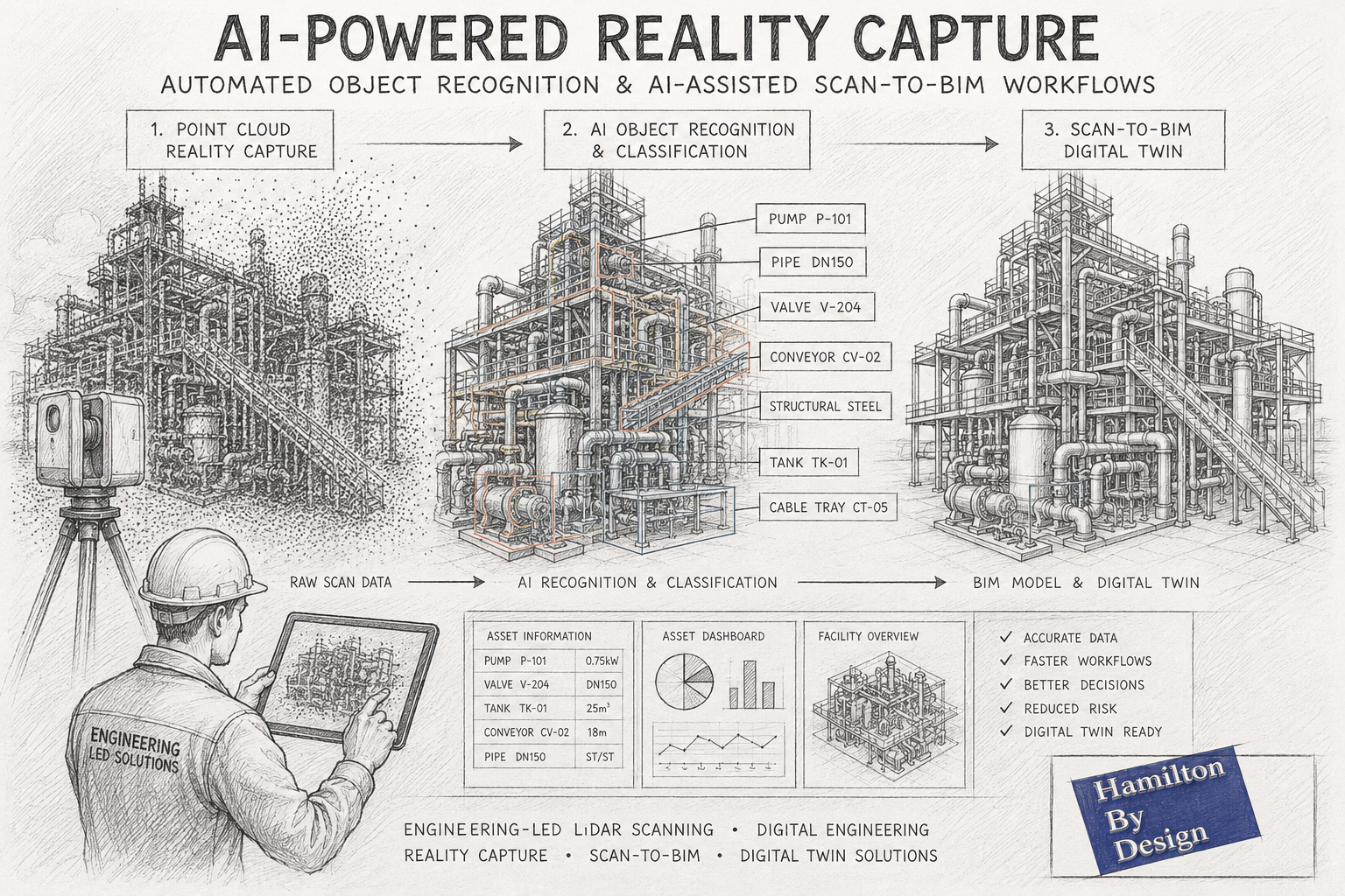
AI-assisted Scan-to-BIM workflow illustrated as a pencil sketch showing an industrial processing plant progressing from LiDAR point cloud capture through automated object recognition to a completed BIM digital twin model.

Automated Object Recognition from Point Clouds and AI-Assisted Scan-to-BIM Workflows

How Artificial Intelligence is Transforming Reality Capture and Digital Engineering

The reality capture industry is experiencing a significant transformation. While terrestrial LiDAR scanning, laser scanning and photogrammetry have been widely adopted across mining, manufacturing, construction and infrastructure sectors for many years, the emergence of Artificial Intelligence (AI) is fundamentally changing how point cloud data is processed and utilised.

Traditionally, converting a point cloud into useful engineering information required substantial manual effort. Engineers, designers and BIM technicians would spend hundreds of hours identifying equipment, tracing pipework, modelling structures and generating asset information from raw scan data.

Today, advances in automated object recognition and AI-assisted Scan-to-BIM workflows are reducing these manual processes and opening new opportunities for asset owners, engineering consultants and project teams.

At Hamilton By Design, we continue to monitor and evaluate emerging AI technologies while combining them with engineering-led reality capture workflows to deliver practical outcomes for industrial and infrastructure projects throughout Australia.


What is Automated Object Recognition?

Automated object recognition refers to the ability of software systems to identify and classify objects within a point cloud automatically.

Instead of manually examining millions or billions of points, AI algorithms analyse geometric patterns, spatial relationships, colours and textures to determine what each object represents.

For example, AI systems may automatically identify:

  • Structural steel members
  • Pipework systems
  • Valves
  • Pumps
  • Conveyors
  • Electrical equipment
  • Cable trays
  • Tanks and vessels
  • Building columns
  • Walls and floors
  • Doors and windows
  • Handrails and platforms
  • Mechanical equipment

The objective is to transform unstructured point cloud data into structured engineering information.

This allows project teams to move from raw scan data to usable digital assets much faster than traditional modelling methods.


Understanding Point Clouds

A point cloud is a collection of millions or billions of measured points captured using:

  • Terrestrial LiDAR scanners
  • Mobile mapping systems
  • Drone LiDAR systems
  • Photogrammetry
  • Structured light scanners
  • Handheld scanning systems

Each point contains spatial coordinates representing a physical location in the real world.

Modern scanners can capture:

  • Plant rooms
  • Industrial facilities
  • Processing plants
  • Mining infrastructure
  • Commercial buildings
  • Manufacturing equipment
  • Transport infrastructure
  • Refineries and smelters

The challenge has never been collecting data.

The challenge is turning that data into engineering information.

This is where AI is beginning to provide significant value.


Why Traditional Point Cloud Processing is Time Consuming

Historically, engineering teams have relied on manual modelling workflows.

A typical process might involve:

  1. Capturing scan data
  2. Registering point clouds
  3. Cleaning noise
  4. Importing into CAD or BIM software
  5. Identifying equipment manually
  6. Modelling structures
  7. Modelling pipework
  8. Generating asset information
  9. Producing drawings and deliverables

For complex facilities such as mines, smelters, power stations and manufacturing plants, this work can require hundreds or even thousands of engineering hours.

Although highly accurate, these workflows can be expensive and time intensive.


How AI is Changing Reality Capture

Artificial Intelligence is introducing a new layer of automation.

Modern AI systems can learn from vast datasets of industrial and architectural objects.

Rather than simply displaying a point cloud, AI attempts to understand what the data represents.

Examples include:

Pipe Recognition

AI algorithms can automatically identify cylindrical features and classify them as pipework.

Software can estimate:

  • Pipe centre lines
  • Pipe diameters
  • Connections
  • Elbows
  • Tees
  • Reducers

Structural Steel Recognition

Machine learning systems can identify:

  • Universal beams
  • Columns
  • Channels
  • Angles
  • Bracing members

This can accelerate structural modelling workflows.

Equipment Classification

AI systems are increasingly capable of identifying:

  • Pumps
  • Motors
  • Gearboxes
  • Tanks
  • Vessels
  • Heat exchangers

Although verification is still required, the process can dramatically reduce manual modelling time.

Building Element Recognition

For architectural and BIM applications, AI can automatically detect:

  • Walls
  • Floors
  • Ceilings
  • Doors
  • Windows
  • Roof systems

This enables faster generation of BIM models.


What is AI-Assisted Scan-to-BIM?

Scan-to-BIM is the process of converting reality capture data into Building Information Models.

Traditionally, BIM technicians manually created geometry based on point cloud information.

AI-assisted Scan-to-BIM introduces automated recognition tools that accelerate this process.

The workflow generally follows:

Step 1 โ€“ Reality Capture

A facility is scanned using terrestrial LiDAR technology.

Hamilton By Design typically captures:

  • Industrial facilities
  • Manufacturing plants
  • Mining infrastructure
  • Commercial buildings
  • Mechanical plant rooms
  • Process facilities

Step 2 โ€“ Point Cloud Registration

Individual scans are combined into a single registered dataset.

The result becomes a complete digital representation of the facility.

Step 3 โ€“ AI Object Recognition

Artificial Intelligence analyses the point cloud.

Potential objects are automatically identified and classified.

Step 4 โ€“ BIM Generation

Recognised objects are converted into BIM components.

This may include:

  • Structural members
  • Architectural features
  • Mechanical equipment
  • Pipework
  • Services

Step 5 โ€“ Engineering Verification

Engineers and BIM specialists verify the results.

This remains one of the most important stages.

AI can accelerate workflows, but engineering judgement remains essential.

Step 6 โ€“ Digital Twin Development

The resulting BIM model can support:

  • Asset management
  • Facility upgrades
  • Maintenance planning
  • Shutdown planning
  • Construction sequencing
  • Digital twin initiatives

Applications in Mining and Heavy Industry

Mining operations generate enormous quantities of asset information.

Facilities often contain:

  • Conveyors
  • Crushers
  • Chutes
  • Screens
  • Tanks
  • Pipework
  • Structural steel
  • Electrical infrastructure

AI-assisted recognition has the potential to significantly improve the efficiency of:

Brownfield Modifications

Existing assets can be scanned and classified more rapidly.

Shutdown Planning

Equipment and access areas can be documented more efficiently.

Asset Registers

Physical assets can be linked to digital asset management systems.

Digital Twin Creation

AI can accelerate the development of operational digital twins.

Condition Assessment

Automated recognition may eventually support condition monitoring and defect identification.


Current Limitations of AI Recognition

Despite impressive progress, AI is not yet capable of fully replacing experienced engineers.

Several challenges remain.

Complex Industrial Environments

Industrial facilities contain:

  • Congested pipework
  • Obstructions
  • Corrosion
  • Dust accumulation
  • Non-standard equipment

These conditions can confuse automated systems.

Unique Equipment

Mining and manufacturing plants often contain custom-built equipment.

AI systems trained on generic datasets may struggle to identify these assets accurately.

Data Quality

Recognition performance depends heavily on:

  • Scan quality
  • Resolution
  • Registration accuracy
  • Coverage

Poor quality input data typically produces poor quality output.

Engineering Intent

AI can identify geometry.

Understanding engineering intent remains much more difficult.

An experienced engineer can determine:

  • Why a system was designed a certain way
  • Potential maintenance issues
  • Access requirements
  • Structural concerns
  • Process constraints

This knowledge is difficult to automate.


Why Engineering Expertise Still Matters

At Hamilton By Design, we believe AI should be viewed as an engineering productivity tool rather than a replacement for engineering expertise.

The highest quality outcomes are achieved when:

  • High-quality scan data is captured
  • AI assists with recognition
  • Engineers validate results
  • Designers refine models
  • Project teams apply practical experience

This hybrid approach combines automation with engineering judgement.

For industrial facilities, this remains the most reliable pathway to accurate digital deliverables.


The Future of AI in Reality Capture

Over the next decade we expect to see:

Faster Model Creation

Many routine modelling tasks will become increasingly automated.

Improved Asset Classification

AI systems will recognise a broader range of industrial equipment.

Automated Drawing Generation

Point clouds may eventually generate engineering drawings automatically.

Predictive Asset Management

Digital twins may combine scan data with operational data to predict failures.

Real-Time Facility Updates

Facilities may continuously update digital models as changes occur.

Intelligent Maintenance Planning

AI systems could identify maintenance requirements before failures occur.


How Hamilton By Design Uses Reality Capture Today

Hamilton By Design provides engineering-led reality capture services throughout Australia.

Our services include:

  • Terrestrial LiDAR scanning
  • Engineering-grade reality capture
  • Point cloud registration
  • Scan-to-CAD
  • Scan-to-BIM
  • Reverse engineering
  • Mechanical design
  • Structural modelling
  • Digital engineering support
  • Asset documentation

We work across:

  • Mining
  • Manufacturing
  • Energy
  • Infrastructure
  • Commercial buildings
  • Water and wastewater facilities

Our focus remains on delivering practical engineering outcomes from accurate measured data.

As AI-assisted workflows continue to mature, we expect these technologies to further enhance project efficiency while maintaining the engineering oversight required for complex industrial environments.


Hamilton By Design logo displayed on a blue tilted rectangle with a grey gradient background

Automated object recognition and AI-assisted Scan-to-BIM workflows represent one of the most exciting developments in the reality capture industry.

The ability to automatically identify equipment, classify assets and accelerate BIM creation has the potential to significantly reduce modelling time while improving access to engineering information.

However, successful implementation still depends on high-quality scan data, robust workflows and experienced engineering oversight.

The future of digital engineering is unlikely to be fully manual or fully automated.

Instead, it will combine advanced reality capture technologies, artificial intelligence and practical engineering expertise to create smarter, more efficient project delivery.

For organisations looking to develop accurate digital representations of existing assets, AI-assisted reality capture is rapidly becoming an important part of the engineering toolkit.


Contact Us – Talk to Us
Name
Would you like us to arrange a phone consultation for you?
Address


Mechanical Engineering | Structural Engineering


3D CAD Modelling Australia service banner for Hamilton By Design
Australian Drafting logo featuring bold white text reading "Australian Drafting" centred on a blue rounded rectangle background.
Engineering Governance title graphic featuring bold white text reading "Engineering Governance" centred on a blue rounded rectangle background.
Mechanical, Structural & Pipework Drafting service banner by Hamilton By Design featuring white text on a blue background.
Mechanical engineering services
Blue rounded button with the text โ€œSolidWorks Designโ€ in white.
Finite Element Analysis (FEA) engineering simulation button
3D LiDAR Scanning Darwin for engineering surveys, laser scanning, reality capture and point cloud modelling services
3D LiDAR Scanning Australia engineering services for laser scanning, reality capture, scan-to-CAD, Scan-to-BIM and as-built documentation across Australia
3D LiDAR scanning services on the Central Coast providing engineering-grade laser scanning, point cloud capture, scan-to-CAD modelling and industrial reality capture for infrastructure and industrial projects.
3D LiDAR Scanning Perth for engineering surveys, laser scanning, reality capture and point cloud modelling services
3D LiDAR Scanning Sydney for engineering surveys, laser scanning, reality capture and point cloud modelling services
3D LiDAR Scanning Brisbane for engineering surveys, laser scanning, reality capture and point cloud modelling services
3D LiDAR Scanning Canberra for engineering surveys, laser scanning, reality capture and point cloud modelling services
3D LiDAR Scanning Newcastle for engineering surveys, laser scanning, reality capture and point cloud modelling services
3D LiDAR Scanning Adelaide for engineering surveys, laser scanning, reality capture and point cloud modelling services
3D LiDAR Scanning Darwin for engineering surveys, laser scanning, reality capture and point cloud modelling services
3D LiDAR Scanning Australia engineering services for laser scanning, reality capture, scan-to-CAD, Scan-to-BIM and as-built documentation across Australia
3D LiDAR scanning services on the Central Coast providing engineering-grade laser scanning, point cloud capture, scan-to-CAD modelling and industrial reality capture for infrastructure and industrial projects.

SolidWorks Point Cloud to CAD Workflow | From LiDAR Scans to Detailed Engineering Drawings

SolidWorks Workflow for Converting Point Cloud Data into Detailed Engineering Drawings

From Reality Capture to Fabrication Documentation

The rapid adoption of terrestrial LiDAR scanning and engineering-grade reality capture technologies has fundamentally changed the way engineering projects are executed. For decades, engineers, designers and BIM specialists have relied on traditional workflows that begin with conceptual layouts, survey control, architectural envelopes or predefined design models. Today, however, many industrial projects start with something entirely different: a point cloud.

Instead of beginning with assumptions about what exists, engineering teams can now begin with measured reality.

This shift has significant implications for how projects are planned, modelled and documented. It also raises an important discussion regarding the role of Building Information Modelling (BIM), top-down modelling techniques and traditional design workflows when accurate point cloud information is available from the outset.

While BIM remains a powerful methodology, reality capture introduces a different way of thinking that is particularly valuable for brownfield, industrial, mining, manufacturing and infrastructure projects.

The reality is that neither approach is universally better than the other.

As with most engineering decisions, it is often a case of horses for courses.


The Rise of Engineering-Grade Reality Capture

Modern terrestrial LiDAR scanners can capture millions of points every second, producing highly accurate three-dimensional representations of existing facilities.

These systems are now routinely used throughout:

  • Mining operations
  • Mineral processing plants
  • Smelters
  • Power stations
  • Water treatment facilities
  • Manufacturing plants
  • Commercial buildings
  • Hospitals
  • Transport infrastructure
  • Refineries

Unlike traditional survey methods that capture selected points, LiDAR scanning captures entire environments.

The resulting point cloud becomes a digital record of reality.

Engineers can then revisit the site virtually, long after the field work has been completed.

This offers significant advantages including:

  • Reduced site visits
  • Improved safety
  • Faster design development
  • Better clash detection
  • Enhanced stakeholder collaboration
  • Improved asset documentation
  • Accurate retrofit design

For industrial facilities where access may be restricted, hazardous or costly, point cloud data often becomes one of the most valuable project assets available.


Understanding Point Clouds

A point cloud is a collection of millions or billions of measured XYZ coordinates.

Each point represents a location in space.

When combined, these points create a highly detailed representation of physical objects including:

  • Structural steel
  • Pipework
  • Equipment
  • Conveyors
  • Tanks
  • Buildings
  • Mechanical components
  • Electrical services
  • Access systems

Modern scanners may also capture colour information, intensity data and imagery, creating a realistic digital twin of the physical environment.

Unlike traditional CAD models, point clouds contain measured information rather than designed information.

This distinction is important.

A CAD model represents what was intended.

A point cloud represents what actually exists.

For brownfield engineering projects this difference can be substantial.


Why Traditional BIM Workflows Can Struggle

Building Information Modelling originated primarily within the architectural and construction sectors.

The traditional BIM process generally follows a sequence such as:

Concept Design โ†’ Schematic Design โ†’ Detailed Design โ†’ Construction โ†’ Asset Management

The model evolves as the project progresses.

In many BIM workflows the process begins with an architectural envelope or predefined design geometry.

Walls, floors, columns and services are created within a structured modelling environment.

This approach works exceptionally well for:

  • New buildings
  • Greenfield developments
  • Commercial construction
  • Architectural projects
  • Civil infrastructure projects

However, industrial facilities rarely fit neatly into these categories.

A mining plant built over 40 years may contain:

  • Multiple undocumented modifications
  • Legacy equipment
  • Inaccurate drawings
  • Informal field changes
  • Missing records
  • Deformed structures
  • Equipment relocations

In these situations the design model is often less accurate than the physical asset itself.

This creates a challenge.

Traditional BIM workflows frequently assume the model is the primary source of truth.

Reality capture reverses that assumption.

The point cloud becomes the source of truth.

The model simply becomes a representation of measured reality.


Reality-First Engineering

A reality-first workflow begins with data acquisition rather than design assumptions.

The process typically follows:

  1. Site Scanning
  2. Point Cloud Registration
  3. Quality Assurance
  4. Point Cloud Optimisation
  5. Model Development
  6. Engineering Analysis
  7. Drawing Production
  8. Construction Documentation

Instead of asking:

“What should this facility look like?”

The workflow asks:

“What does this facility actually look like?”

This subtle change can significantly improve project outcomes.


SolidWorks and Point Cloud Modelling

SolidWorks has evolved into a powerful platform for working with reality capture data.

While originally developed as a mechanical design system, modern versions provide excellent capabilities for integrating scan data into engineering workflows.

Point clouds can be imported through various formats including:

  • E57
  • LAS
  • XYZ
  • PLY
  • STL
  • OBJ
  • Mesh formats

Depending on project requirements, the workflow may involve:

  • Direct point cloud reference
  • Mesh generation
  • Surface modelling
  • Parametric feature creation
  • Reverse engineering
  • Assembly development

The chosen approach depends on the intended deliverable.


The Importance of Top-Down Modelling

Top-down modelling becomes particularly valuable when working from point cloud data.

Traditional bottom-up modelling involves creating individual components separately before assembling them.

Top-down modelling reverses this process.

The assembly becomes the master model.

Individual components are then developed within the context of the larger system.

For industrial facilities this approach offers significant advantages.


Why Top-Down Modelling Works Well with Point Clouds

A point cloud already contains contextual information.

Pipework exists relative to equipment.

Equipment exists relative to structures.

Structures exist relative to buildings.

Everything already has a defined relationship.

Top-down modelling allows engineers to preserve these relationships.

For example:

A conveyor transfer chute may be modelled directly within the context of:

  • Existing conveyor structure
  • Existing walkways
  • Existing pipework
  • Existing electrical services
  • Existing maintenance access

The design develops within the reality captured environment.

This significantly reduces the risk of clashes.


Skeleton Models and Layout Control

One of the most effective top-down approaches involves the use of skeleton models.

A skeleton model contains:

  • Key reference geometry
  • Design planes
  • Centre lines
  • Control sketches
  • Interface locations

When working from point clouds, the skeleton model can be created directly from measured geometry.

This establishes a reliable framework for the remainder of the design.

Individual components then inherit relationships from the skeleton model.

Benefits include:

  • Improved consistency
  • Faster design changes
  • Better design intent control
  • Reduced assembly errors

Scan-to-CAD Workflow

A typical Scan-to-CAD workflow within SolidWorks may follow the following sequence.

Step 1 โ€“ Site Capture

Engineering-grade LiDAR scanning is completed on site.

Data is collected from multiple scanner positions.

The objective is to capture sufficient coverage while maintaining registration quality.


Step 2 โ€“ Registration

Individual scans are registered into a unified coordinate system.

This produces a complete point cloud.

Quality control is performed to verify registration accuracy.

Typical industrial projects may achieve overall accuracies within several millimetres.


Step 3 โ€“ Point Cloud Cleaning

Noise is removed.

Unwanted objects may be filtered.

Temporary equipment can be excluded.

The objective is to create a usable engineering dataset.


Step 4 โ€“ Import into Modelling Environment

The point cloud is imported into the modelling platform.

At this stage the cloud becomes a digital reference.

The cloud itself is generally not modified.

Instead, engineering geometry is created around it.


Step 5 โ€“ Create Reference Geometry

Reference planes, axes and coordinate systems are established.

These form the foundation of the modelling process.

Top-down methodologies become particularly valuable at this stage.


Step 6 โ€“ Build Parametric Models

Engineering components are modelled using parametric features.

Examples include:

  • Structural steel
  • Tanks
  • Pipework
  • Chutes
  • Platforms
  • Conveyors
  • Ductwork

The resulting model remains editable and fully configurable.


Step 7 โ€“ Validation

The model is compared against the point cloud.

Engineers verify fit, alignment and geometry.

Potential clashes are identified early.


Step 8 โ€“ Drawing Production

Detailed drawings are generated directly from the validated model.

Deliverables may include:

  • General arrangements
  • Fabrication drawings
  • Assembly drawings
  • Pipe spool drawings
  • Structural steel details
  • Installation drawings
  • Bill of materials

Reverse Engineering Using Point Clouds

Reverse engineering is one of the most powerful applications of reality capture.

Many industrial facilities contain components with:

  • Missing drawings
  • Obsolete equipment
  • Unknown suppliers
  • Legacy modifications

Point clouds provide a practical starting point.

Engineers can recreate:

  • Mechanical components
  • Structural systems
  • Pipework networks
  • Fabricated assemblies

The resulting CAD models become valuable engineering assets.


Parametric Models versus Mesh Models

A common mistake is assuming that a mesh model is equivalent to a CAD model.

It is not.

A mesh represents geometry.

A parametric model represents engineering intent.

This distinction is critical.

A parametric SolidWorks model allows:

  • Dimension changes
  • Configuration control
  • Design modifications
  • Manufacturing documentation
  • Finite element analysis

For most engineering applications, converting point clouds into intelligent parametric models provides significantly greater value than simply generating meshes.


Producing Detailed Engineering Drawings

Once a validated model exists, drawing production becomes straightforward.

SolidWorks can automatically generate:

  • Orthographic views
  • Sections
  • Detail views
  • Exploded views
  • Bills of materials
  • Weldment cut lists

This dramatically reduces drafting effort.

Because the drawings originate from the model, consistency is maintained throughout the project.


Brownfield Projects Benefit Most

The reality-first workflow delivers the greatest value in brownfield environments.

These include:

  • Operating mines
  • Smelters
  • Refineries
  • Processing plants
  • Manufacturing facilities
  • Water treatment plants

In these environments accurate existing-condition information is often more valuable than historic drawings.

A point cloud provides a measurable record of the asset as it exists today.


BIM versus Point Cloud Driven Engineering

This discussion is sometimes framed as:

“BIM versus Reality Capture.”

In practice this is the wrong question.

Reality capture and BIM should not be viewed as competing technologies.

They solve different problems.

BIM provides:

  • Information management
  • Design coordination
  • Asset lifecycle management
  • Construction planning
  • Facility management integration

Reality capture provides:

  • Existing-condition verification
  • Accurate geometry
  • Retrofit design support
  • Asset documentation
  • Digital twin creation

The most successful projects often combine both approaches.


A Modern Hybrid Workflow

Increasingly, engineering organisations are adopting a hybrid workflow.

The process becomes:

Reality Capture โ†’ Engineering Model โ†’ BIM Integration

Rather than creating BIM models based on assumptions, the BIM environment is populated using measured reality.

This approach improves confidence throughout the project lifecycle.

The BIM system benefits from more accurate geometry.

The engineering team benefits from reliable site information.

The asset owner benefits from better data quality.

Everybody wins.


The Future of Digital Engineering

The future of engineering is likely to become increasingly reality driven.

Advancements in:

  • LiDAR technology
  • Mobile scanning
  • Drone scanning
  • Artificial Intelligence
  • Automated feature extraction
  • Digital twins

will continue to accelerate the adoption of reality capture workflows.

However, traditional engineering principles remain essential.

Engineers still need to understand:

  • Design intent
  • Structural behaviour
  • Manufacturing processes
  • Construction methods
  • Asset management requirements

Technology provides information.

Engineering provides understanding.


SolidWorks provides an exceptionally capable platform for converting point cloud data into detailed engineering models and fabrication drawings. When combined with top-down modelling methodologies, point clouds become far more than visual references; they become the foundation of the engineering workflow.

Traditional BIM methodologies remain highly effective for greenfield projects and building-centric developments where the design model drives project delivery. However, in brownfield industrial environments the reality often differs from the original design documentation. In these situations, a point cloud frequently becomes the most accurate representation of the asset available.

Rather than viewing BIM and reality capture as competing philosophies, modern engineering teams should recognise the strengths of each approach. BIM excels at information management, coordination and lifecycle planning, while point cloud-driven workflows excel at capturing existing conditions and enabling accurate retrofit design.

Ultimately, the most effective solution is often a hybrid approach that combines the strengths of both. By starting with measured reality, developing intelligent parametric models in SolidWorks and integrating those models into broader BIM environments where appropriate, engineers can reduce risk, improve accuracy and deliver higher quality outcomes.

As digital engineering continues to evolve, the question is no longer whether point clouds should be used. The question is how effectively organisations can transform reality capture data into actionable engineering information that supports design, construction, operation and long-term asset management.

Hamilton By Design logo displayed on a blue tilted rectangle with a grey gradient background

Contact Us – Talk to Us
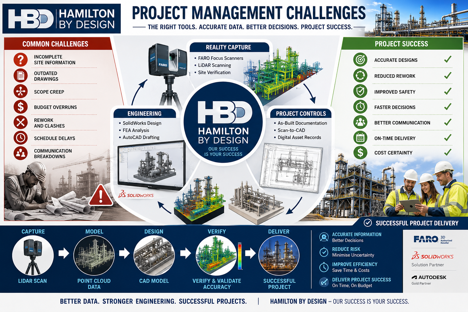
Name
Would you like us to arrange a phone consultation for you?

Address

Our Clients:

3D CAD Modelling Australia service banner for Hamilton By Design
3D LiDAR scanning and 3D modelling service button โ€” laser scanner capturing a point cloud for engineering and CAD modelling
Mechanical engineering services
3D CAD Modelling Australia service banner for Hamilton By Design
Mechanical, Structural & Pipework Drafting service banner by Hamilton By Design featuring white text on a blue background.
Australian Drafting logo featuring bold white text reading "Australian Drafting" centred on a blue rounded rectangle background.
Blue banner graphic displaying the text "Point Cloud to CAD - Australia" in large white lettering, representing point cloud processing, scan-to-CAD conversion and digital engineering services across Australia.
CHPP Engineering title graphic featuring bold white text reading "CHPP Engineering" centred on a blue rounded rectangle background.
Engineering Governance title graphic featuring bold white text reading "Engineering Governance" centred on a blue rounded rectangle background.
Mechanical engineering services
Australian Drafting logo featuring bold white text reading "Australian Drafting" centred on a blue rounded rectangle background.
3D LiDAR Scanning Hunter & Newcastle banner with white text on a blue background promoting engineering-grade laser scanning services for industrial, mining and infrastructure projects across the Hunter Valley and Newcastle region.
Mechanical Engineering Hunter & Newcastle banner promoting mechanical engineering services for mining, industrial plants, power generation, manufacturing and heavy industry throughout the Hunter Valley and Newcastle region.
Structural Drafting Hunter & Newcastle banner promoting structural drafting services for mining, industrial plants, power generation, manufacturing and infrastructure projects across the Hunter Valley and Newcastle region.
Mechanical Engineering Perth WA banner for Hamilton By Design featuring white text on a blue background.
3D Laser Scanning Perth WA banner for Hamilton By Design with white text on a blue background.
SolidWorks Perth WA banner for Hamilton By Design featuring white text on a blue background.
Fabrication and product design services
Finite Element Analysis (FEA) engineering simulation button
3D LiDAR scanning and 3D modelling service button โ€” laser scanner capturing a point cloud for engineering and CAD modelling
Blue rounded button with the text โ€œSolidWorks Designโ€ in white.
Mechanical drafting services button
Structural drafting services button

Mechanical Engineering | Structural Engineering


3D LiDAR Scanning Darwin for engineering surveys, laser scanning, reality capture and point cloud modelling services
3D LiDAR Scanning Australia engineering services for laser scanning, reality capture, scan-to-CAD, Scan-to-BIM and as-built documentation across Australia
3D LiDAR scanning services on the Central Coast providing engineering-grade laser scanning, point cloud capture, scan-to-CAD modelling and industrial reality capture for infrastructure and industrial projects.