AS 3990 Mechanical Equipment Steelwork | Walkways, Platforms & Conveyor Structures

Engineer using LiDAR scanner to capture as-built tank steelwork, transitioning to compliant AS 3990 walkways and access platforms

AS 3990 โ€“ Mechanical Equipment Steelwork

Walkways, Conveyor Structures, Platforms and Gantries

Mechanical equipment steelwork is everywhere in industrial sites โ€” conveyor structures, access walkways, maintenance platforms, gantries and support frames. Over time, these structures are modified, loaded differently, repaired, and upgraded. Thatโ€™s where AS 3990 โ€“ Mechanical equipment โ€“ Steelwork becomes critical: it provides a framework for designing and verifying steelwork that supports mechanical equipment and associated access systems.

At Hamilton By Design, we help asset owners and project teams reduce risk by converting real as-built steelwork into engineering-grade digital models that can be checked, upgraded, and documented with confidence.
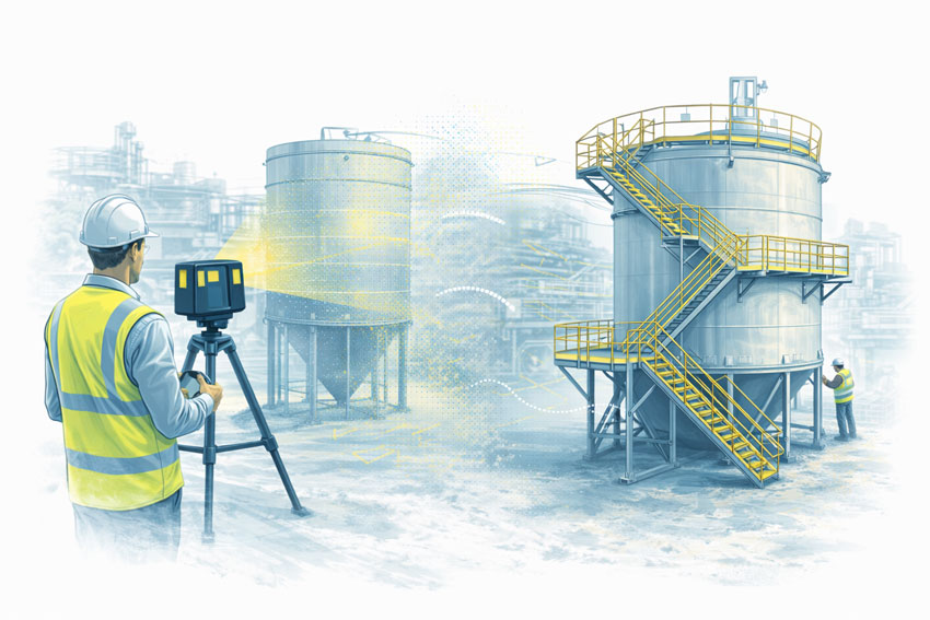

3D LiDAR scanning of industrial tank steelwork showing as-built condition and engineered walkways and stairs designed to AS 3990

When AS 3990 Steelwork Becomes a Problem in the Real World

Steelwork rarely fails because it was โ€œobviously wrongโ€ on day one. The most common issues develop gradually due to changes in loading, upgrades, corrosion, or incomplete documentation.

Common triggers we see on site

  • New conveyor drives, chutes, skirts, guards, or pull-wire systems added after commissioning
  • Extra services added: cable trays, hose reels, water lines, pipework, and supports
  • Walkway changes for access, maintenance, or guarding upgrades
  • Localised damage from impact, vibration, or operational fatigue
  • Corrosion or section loss in wash-down areas, coastal environments, or chemical exposure zones
  • Legacy steelwork with missing drawings or unknown load assumptions

If you canโ€™t prove what exists (accurately), it becomes difficult to prove compliance, fitness-for-purpose, or due diligence.


Key Engineering Risks with Walkways, Platforms, Gantries and Conveyor Structures

1) Design intent vs as-built reality

Many sites have steelwork that differs from drawings due to shutdown modifications or brownfield constraints. Small deviations in member size, connection detailing, or geometry can materially change structural performance.

2) Loads have changed โ€” but the steelwork didnโ€™t

A โ€œsimpleโ€ modification can add significant load: added services, heavier equipment, changed maintenance practices, or multiple personnel working in the same bay. These changes can push members or connections beyond the original assumptions.

3) Conveyor vibration and dynamic effects

Conveyor structures experience cyclic loading, start/stop effects, and vibration. Even if the structure looks acceptable, fatigue and resonance can become a long-term reliability problem โ€” particularly around drive stations, transfer points, and cantilevered platforms.

4) Connection adequacy often governs

Field-welded brackets, modified gussets, bolt slip, corroded fasteners, and non-standard connection geometry can become the weak link. Connection performance is frequently the true limiting factor in older or heavily modified steelwork.

5) Access and safety interfaces

Walkways and platforms often sit at the intersection of multiple requirements: safe access geometry, handrails, toe-boards, gates, and guarding. If access steelwork was modified without a proper verification step, the risk becomes both structural and safety-related.


What โ€œVerificationโ€ Looks Like in Practice

AS 3990 steelwork compliance is not just a box-tick. In a practical project environment, it means you can answer:

  • What steelwork exists right now (as-built)?
  • What loads and operational conditions apply today (not ten years ago)?
  • Are members and connections adequate under realistic scenarios?
  • What upgrades are required, and can they be fabricated to fit first time?
  • Can the asset owner document compliance and risk controls for governance?

Hamilton By Design supports this process by bringing LiDAR scanning + mechanical engineering + fabrication-ready outputs together under one roof.


How Hamilton By Design Helps (Our Typical Deliverables)

1) Engineering-grade 3D LiDAR scanning of steelwork

We capture accurate geometry of:

  • Walkways and access platforms
  • Conveyor stringers, trestles, and transfer towers
  • Gantries, monorails, and maintenance frames
  • Supports, bracing, ladders, stairs, and access interfaces

Related service:
3D Laser Scanning: https://www.hamiltonbydesign.com.au/3d-laser-scanning/

2) As-built CAD model for verification and design

We convert the scan into usable engineering outputs such as:

  • As-built 3D CAD models
  • Key dimensions, levels, and clearances
  • Interference checking and fit-up planning
  • Fabrication-ready drawings for retrofit steelwork

3) Engineering checks and upgrade design

Where required, we support structural verification and upgrade design using engineering workflows suited to brownfield assets.

Related capability:
SolidWorks FEA / simulation workflows: https://www.hamiltonbydesign.com.au/home/solidworks/solidworks-fea-simulation/


Where This Matters Most (Typical Applications)

  • Conveyor upgrades and transfer station modifications
  • Walkway widening, new stair access, and maintenance platform additions
  • Guarding upgrades, pull-wire additions, and access compliance programs
  • Corrosion repairs and local strengthening
  • Brownfield plant modifications with limited shutdown time
  • Audit readiness and engineering documentation clean-up

If youโ€™re working around conveyors, you may also find this relevant:
AS 1755 Conveyor Safety: https://www.hamiltonbydesign.com.au/as-1755-conveyor-safety/

And for safety leadership context:
Machine guarding lessons: https://www.hamiltonbydesign.com.au/machine-guarding-in-australia-a-decade-of-lessons-for-leaders-asset-owners-and-engineers/


Standards and Compliance Context (How AS 3990 Fits In)

AS 3990 typically sits alongside a broader compliance context depending on the asset and scope. In many industrial environments, it may interact with standards and guidance such as:

  • AS 1657 (fixed platforms, walkways, stairways and ladders)
  • AS 4100 (steel structures)
  • AS/NZS 1170 (structural actions / loading)
  • AS 1755 (conveyor safety and associated interfaces)

For official sources and governance context:

(Note: Always confirm the current revision and applicability of standards for your site, scope, and jurisdiction.)


Why Digital As-Built Matters for AS 3990 Steelwork

A verified as-built model reduces:

  • Upgrade risk and fabrication rework
  • Shutdown time lost to unexpected clashes
  • Safety risks from undocumented modifications
  • Compliance gaps during audits and governance reviews

It also supports โ€œfit-first-timeโ€ fabrication because designers, engineers, and fabricators are working from the same geometry โ€” not assumptions.


Talk to an Engineer About Your AS 3990 Steelwork

If youโ€™re planning an upgrade, responding to an audit, or unsure whether existing walkways, platforms, gantries or conveyor structures still meet their intended duty, we can help you quickly establish a reliable baseline.

Start with scanning, modelling, and engineering verification โ€” and build from facts.

Related service pages to explore:

Hamilton By Design logo displayed on a blue tilted rectangle with a grey gradient background
3D LiDAR scanning and 3D modelling service button โ€” laser scanner capturing a point cloud for engineering and CAD modelling
Mechanical engineering services

Our clients:

Name
Would you like us to arrange a phone consultation for you?
Address
https://youtu.be/jOGYoLL1Vro?si=vPkEAPQiFzB9fd6-

Mechanical Engineering | Structural Engineering


AS 3774 โ€“ Loads on Bulk Solids Containers: Why It Matters for Safety and Compliance

Engineer using 3D LiDAR scanner to capture silos, hoppers, bins, and bulk solids containers at an industrial processing plant.

AS 3774 โ€“ Loads on Bulk Solids Containers | Safety & Compliance

AS 3774 Loads on Bulk Solids Containers exists for a simple reason:
bulk solids do not behave like fluids, and incorrect load assumptions can create serious structural and safety risks.

For asset owners, engineers, and project teams involved in mining, mineral processing, manufacturing, and bulk materials handling, AS 3774 provides the framework for understanding how loads actually develop in silos, bins, hoppers, chutes, transfer stations, and surge bins.

Yet despite its long-standing availability, many new installations are still being delivered without full consideration of AS 3774 load cases.

The risks created by this gap are often not immediately visible โ€” but they are very real.


Engineer using 3D LiDAR scanner to capture silos, hoppers, bins, and bulk solids containers at an industrial processing plant.

What AS 3774 Is Designed to Address

AS 3774 recognises that bulk solids behave in complex and sometimes counter-intuitive ways. Unlike liquids, bulk materials:

  • Develop non-uniform wall pressures
  • Apply eccentric and asymmetric loads
  • Change load paths depending on flow behaviour
  • Generate dynamic and cyclic forces during filling and discharge

The standard provides guidance for determining realistic design loads based on how material actually flows and interacts with container geometry.

This applies across all bulk solids containers, including:

  • Silos
  • Bins and surge bins
  • Hoppers
  • Chutes and transfer stations
  • Rail and ship loading structures
  • Feeders integrated with bins

Why Safety and Compliance Depend on AS 3774

The purpose of AS 3774 is not academic. It exists to prevent outcomes such as:

  • Progressive wall deformation
  • Fatigue cracking and bolt failure
  • Local buckling or plate tearing
  • Uncontrolled discharge or blockage release
  • Unexpected load transfer into supporting structures

What makes these issues particularly dangerous is that they often develop over time, not at commissioning.

A structure can appear โ€œfineโ€ on day one โ€” while accumulating damage due to:

  • Cyclic loading
  • Eccentric discharge patterns
  • Inaccurate assumptions about material properties
  • Mixed construction materials behaving differently over time

Common Design Assumptions That Create Hidden Risk

In practice, many bulk solids containers are still designed using simplified or incorrect assumptions, including:

1. Treating Bulk Solids Like Fluids

Uniform hydrostatic pressure assumptions do not reflect real wall loading patterns and can significantly under-predict peak stresses.

2. Ignoring Eccentric Discharge

Off-centre outlets, partial blockages, or asymmetric flow paths can introduce large bending and torsional effects that are not obvious from geometry alone.

3. Incorrect or Assumed Material Properties

Bulk density, cohesion, moisture content, and flow behaviour are often assumed rather than verified โ€” yet small changes can have large load implications.

4. Mixed Materials Without Long-Term Consideration

It is not uncommon to see hoppers fabricated from a combination of stainless steel and mild steel, without adequate consideration of:

  • Differential stiffness
  • Fatigue behaviour
  • Corrosion mechanisms
  • Galvanic interaction

These issues may not present as immediate failures, but they can significantly reduce structural life and reliability.


Why the Risk Is Often Not Evident Today

One of the most concerning aspects of non-compliance with AS 3774 is that failure is rarely immediate.

Instead, risk accumulates quietly through:

  • Repeated filling and discharge cycles
  • Minor operational changes
  • Variations in material condition
  • Small geometric imperfections

By the time visible cracking, deformation, or operational issues appear, the structure may already be compromised.


The Role of Modern Engineering Tools (Briefly)

While AS 3774 is fundamentally about load determination, modern engineering tools can support compliance by helping teams:

  • Verify as-built geometry against design assumptions
  • Identify eccentric discharge paths and flow constraints
  • Review interfaces, wall angles, and structural continuity
  • Support independent engineering assessment without extended shutdowns

These tools do not replace the standard โ€” but they can help reveal whether its principles have been properly applied.


What Asset Owners and Project Managers Should Ask For

To demonstrate that AS 3774 has been adequately considered, asset owners and project managers should expect to see clear answers to questions such as:

  • What load cases were considered under AS 3774?
  • How were discharge conditions defined and assessed?
  • What assumptions were made about material properties?
  • How were eccentric and asymmetric loads addressed?
  • Was fatigue or cyclic loading considered?
  • How were mixed materials and interfaces assessed?
  • Has an independent engineering review been undertaken?

If this information cannot be clearly provided, compliance is difficult to demonstrate, regardless of how new the installation is.


Hamilton By Design logo displayed on a blue tilted rectangle with a grey gradient background
3D LiDAR scanning and 3D modelling service button โ€” laser scanner capturing a point cloud for engineering and CAD modelling
Mechanical engineering services

Why This Matters for New Installations

AS 3774 compliance is not about legacy assets or historical practices.
It is about ensuring that new installations are fit for purpose, safe, and defensible.

Where bulk solids containers are being delivered today without adequate consideration of realistic load behaviour, the risk is being transferred downstream โ€” to operators, maintainers, and asset owners.


Our clients


A Practical Closing Thought

If you are unsure whether AS 3774 has been properly applied to a bulk solids container, an independent engineering review can provide clarity.

The cost of verifying load assumptions and structural adequacy is typically minor compared to the consequences of discovering load-related issues after commissioning.

Hamilton By Design supports asset owners and project teams with engineering review, verification, and redesign of bulk solids containers, helping ensure that safety and compliance are addressed before problems develop.

Name
Would you like us to arrange a phone consultation for you?
Address
Finite Element Analysis (FEA) engineering simulation button
Mechanical engineering services

Mechanical Engineering | Structural Engineering


3D Engineering in Melbourne

Hamilton By Design delivers 3D engineering services in Melbourne that enable designers and engineers to develop solutions based on measured reality, not assumptions.

By combining engineering-grade laser scanning, point cloud modelling, and coordinated 3D CAD environments, we support better decision-making across construction, infrastructure, industrial, and asset-upgrade projects throughout Melbourne and Victoria.


Why 3D Engineering Changes Design Outcomes

Traditional design workflows often rely on:

  • Incomplete as-built drawings
  • Historical documentation of unknown accuracy
  • Assumptions about alignment, levels, and clearances

A 3D engineering model replaces uncertainty with verified spatial data.

When designers work inside a coordinated 3D environment, they gain:

  • Full visibility of existing conditions
  • Early identification of constraints
  • Clear understanding of interfaces
  • Confidence that the proposed design can actually be built

This is especially critical for brownfield sites, upgrades, and staged construction works common across Melbourne.


3D Models Enable Better Scope-Driven Design

Every engineering project is governed by scope โ€” what is changing, what remains, and what must interface correctly.

A 3D model allows designers to:

  • Test multiple design options against real constraints
  • Validate that scope assumptions are correct
  • Adjust layouts before drawings are issued
  • Reduce downstream RFIs and site rework

Instead of designing to drawings, teams design to reality.


Laser Scanning as the Foundation of 3D Engineering

Accurate 3D engineering begins with accurate capture.

Our Melbourne workflows are built on professional LiDAR scanning that produces dense, structured point cloud data suitable for engineering use.

Related service:
3D Laser Scanning & Engineering Services Across Melbourne
https://www.hamiltonbydesign.com.au/home/engineering-services/3d-laser-scanning/3d-laser-scanning-melbourne/

This data provides the spatial foundation upon which all subsequent design decisions are made.


Point Cloud Modelling for Engineering Use

Point clouds are not just visual references โ€” when structured correctly, they become engineering data.

Designers can:

  • Measure directly within the model
  • Verify clearances and tolerances
  • Align new works to existing geometry
  • Confirm plumb, level, and deformation

This approach underpins many Melbourne projects where existing assets must remain operational during upgrades.

Related capability:
Mechanical Engineering & LiDAR Scanning in Melbourne
https://www.hamiltonbydesign.com.au/mechanical-engineering-lidar-scanning-melbourne/


3D Engineering for Construction & Retrofit Projects

For construction and retrofit projects, 3D engineering models support:

  • Constructability reviews
  • Clash detection prior to site works
  • Trade coordination
  • Installation sequencing

Design intent can be validated before materials are fabricated or ordered, reducing cost and schedule risk.

Melbourne scanning and modelling services are coordinated under:
3D Scanning Melbourne
https://www.hamiltonbydesign.com.au/category/engineering-consulting-services/3d-laser-scanning/3d-scanning-melbourne/


Our clients


Better Information = Better Engineering Decisions

A 3D engineering model allows designers to answer critical questions early:

  • Will it fit?
  • Can it be installed?
  • Does it clash with existing services?
  • Is the assumed geometry actually correcting?
  • Can this be built safely and efficiently?

By resolving these questions digitally, engineering teams reduce uncertainty and improve outcomes across the entire project lifecycle.


Hamilton By Design logo displayed on a blue tilted rectangle with a grey gradient background
3D LiDAR scanning and 3D modelling service button โ€” laser scanner capturing a point cloud for engineering and CAD modelling
Mechanical engineering services

Why Hamilton By Design in Melbourne

  • Engineering-led scanning and modelling
  • 3D models built from verified site data
  • Strong integration between capture, CAD, and engineering review
  • Experience with brownfield, retrofit, and complex sites
  • Models that support real design decisions โ€” not just visuals

We donโ€™t just create 3D models.
We create engineering environments that designers can trust.


Discuss Your 3D Engineering Requirements in Melbourne

If your project requires accurate information to support design decisions, Hamilton By Design can assist with 3D engineering in Melbourne from initial capture through to coordinated model delivery.

Contact us to discuss your scope and design requirements.

Name
Would you like us to arrange a phone consultation for you?
Address

3D CAD Modelling Australia service banner for Hamilton By Design


CHPP Engineering title graphic featuring bold white text reading "CHPP Engineering" centred on a blue rounded rectangle background.
Pipework Drafting title graphic featuring bold white text reading "Pipework Drafting" centred on a blue rounded rectangle background.
3D LiDAR Scanning for Engineering Projects title graphic featuring bold white text on a blue rounded rectangle background.


Finite Element Analysis (FEA) engineering simulation button
Structural drafting services button
Mechanical drafting services button


Australian Drafting logo featuring bold white text reading "Australian Drafting" centred on a blue rounded rectangle background.
Engineering Governance title graphic featuring bold white text reading "Engineering Governance" centred on a blue rounded rectangle background.
Engineering-Grade LiDAR Scanning title graphic featuring bold white text on a blue rounded rectangle background.


Mechanical drafting services button
Structural drafting services button


Fabrication and product design services
3D CAD Modelling Australia service banner for Hamilton By Design
Mechanical, Structural & Pipework Drafting service banner by Hamilton By Design featuring white text on a blue background.


3D LiDAR scanning and 3D modelling service button โ€” laser scanner capturing a point cloud for engineering and CAD modelling
Mechanical engineering services

3D CAD Designer in Sydney

An engineer reviews detailed structural steel drawings at a drafting table while an engineering-grade LiDAR scan captures an existing waterfront structure in Sydney, illustrating data-driven structural drafting based on accurate as-built conditions.

3D CAD Designer in Sydney

Structural engineering drafting icon showing a seated engineer working at a drafting table in blue vector style.

Hamilton By Design provides engineering-led 3D CAD design services in Sydney, supporting construction, infrastructure, manufacturing, and industrial projects where accuracy, coordination, and certifiable outcomes matter.

Our Sydney-based 3D CAD services are built on measured reality, using professional laser scanning and point cloud data to ensure that CAD models reflect what truly exists on site โ€” not assumptions taken from legacy drawings or incomplete information.

This approach reduces risk, prevents rework, and supports engineers, builders, and asset owners in delivering reliable outcomes.


Engineering-Grade 3D CAD Design

A 3D CAD designer working on engineering projects must do more than โ€œdraw in 3Dโ€. Engineers rely on CAD models to:

  • Produce certified drawings
  • Verify interfaces and tolerances
  • Coordinate structural and mechanical elements
  • Support construction sequencing and installation
  • Reduce clashes and site modifications

Our CAD designers work as part of an integrated engineering workflow, aligned with how designs are reviewed, approved, and built in Sydney.


CAD Built from Real-World Data

Where projects involve existing buildings, plant, or infrastructure, our CAD models are developed directly from LiDAR scan data, ensuring dimensional accuracy and spatial confidence.

This service is closely linked with:

๐Ÿ‘‰ 3D CAD in Sydney

By working from point clouds rather than assumptions, designers and engineers gain a reliable digital environment for decision-making.


Scan to CAD for Sydney Projects

For brownfield upgrades, refurbishments, and complex construction sites, Scan to CAD is often essential.

Our Sydney Scan-to-CAD workflows support:

  • As-built documentation
  • Retrofit and upgrade design
  • Structural and mechanical coordination
  • Construction planning and verification

Related service:
๐Ÿ‘‰ Scan to CAD Sydney


Supporting Construction & Engineering Teams

Our 3D CAD designers regularly support Sydney construction and engineering teams by delivering models suitable for coordination, shop detailing, and constructability review.

This includes integration with:

  • Structural steel
  • Mechanical equipment
  • Pipework and conveyors
  • Building services and plant layouts

For construction-focused workflows, see:
๐Ÿ‘‰ 3D Construction Scan in Sydney


Point Cloudโ€“Driven CAD Modelling

When accuracy is critical, point cloud data provides the foundation for defensible CAD models.

Our designers work directly with registered engineers and project teams using structured point cloud models that support:

  • Dimensional verification
  • Clearance checking
  • Interface validation
  • Clash detection

Related capability:
๐Ÿ‘‰ 3D Point Cloud Modelling in Sydney


Our clients:


Why Choose Hamilton By Design in Sydney

  • Engineering-led CAD workflows
  • CAD models based on measured reality
  • Strong integration with laser scanning and point clouds
  • Experience across construction, industrial, and infrastructure projects
  • Models suitable for certified and reviewed engineering outcomes

We do not offer generic drafting. We provide 3D CAD design that engineers can rely on.


Hamilton By Design logo displayed on a blue tilted rectangle with a grey gradient background
3D LiDAR scanning and 3D modelling service button โ€” laser scanner capturing a point cloud for engineering and CAD modelling
Mechanical engineering services

Talk to a Sydney-Based 3D CAD Designer

If your project requires accurate CAD models built from real site conditions, Hamilton By Design can support your Sydney project from scan through to CAD delivery.

๐Ÿ“ฉ Contact us to discuss your 3D CAD designer requirements in Sydney.

Name
Would you like us to arrange a phone consultation for you?
Address
3D Scanning Sydney banner promoting engineering-grade 3D laser scanning, LiDAR scanning, and reality capture services by Hamilton By Design.
Mechanical Engineering Sydney banner with white text on a blue background representing Hamilton By Design's mechanical engineering services in Sydney.
Mechanical Drafting and 3D Modelling Sydney banner highlighting Hamilton By Design's CAD drafting, 3D modelling, and engineering design services in Sydney.

Hamilton By Design provides engineering-led 3D scanning, LiDAR scanning, mechanical engineering and digital engineering services throughout Sydney and Greater Sydney.

Explore our related Sydney services:


  • 3D Scanning Sydney โ€“ Engineering-grade terrestrial laser scanning, as-built surveys and point cloud capture for industrial, infrastructure and commercial projects.
  • Reality Capture Sydney โ€“ High-accuracy reality capture, digital twins, asset documentation and engineering-grade site verification.
  • Scan to CAD Sydney โ€“ Convert point cloud data into AutoCAD, SolidWorks, Inventor and other engineering-ready CAD deliverables.
  • Point Cloud Modelling Sydney โ€“ Engineering-grade point cloud processing, clash detection, as-built verification and 3D modelling.
  • Mechanical Engineering Sydney โ€“ Mechanical design, plant upgrades, materials handling systems, conveyors, chutes, platforms and engineering support.
  • Structural Drafting Sydney โ€“ Structural steel drafting, fabrication drawings, GA drawings, workshop detailing and as-built documentation.

Hamilton By Design supports projects throughout Sydney CBD, Parramatta, Liverpool, Penrith, Blacktown, Chatswood, Alexandria, Mascot, Newcastle and the Central Coast.


Blue banner graphic displaying the text "Point Cloud to CAD - Australia" in large white lettering, representing point cloud processing, scan-to-CAD conversion and digital engineering services across Australia.
Blue banner graphic displaying the text "Scan to CAD Sydney" in large white lettering, representing engineering-led point cloud to CAD conversion, LiDAR scanning and digital engineering services in Sydney.
Blue banner graphic displaying the text "Reality Capture Sydney - CBD" in large white lettering, representing engineering-led reality capture, LiDAR scanning and digital engineering services within Sydney CBD commercial buildings and infrastructure.

Mechanical Engineering | Structural Engineering


3D LiDAR Scanning Darwin for engineering surveys, laser scanning, reality capture and point cloud modelling services
3D LiDAR Scanning Australia engineering services for laser scanning, reality capture, scan-to-CAD, Scan-to-BIM and as-built documentation across Australia
3D LiDAR scanning services on the Central Coast providing engineering-grade laser scanning, point cloud capture, scan-to-CAD modelling and industrial reality capture for infrastructure and industrial projects.

AS 4324.1 Brownfield Bulk Handling Assets: Engineering Mobile Equipment for Todayโ€™s Mine Sites

AS 4324.1 Bulk Handling Equipment | Brownfield Stacker & Reclaimer Engineering

Mobile equipment for the continuous handling of bulk materialsโ€”such as stackers, reclaimers, and ship loadersโ€”forms the backbone of Australiaโ€™s mining and export infrastructure. Many of these assets operate continuously in demanding environments, often well beyond their original design life.

Australian Standard AS 4324.1 provides essential guidance for the design and safe operation of this class of equipment. However, on many Australian mine sites, the practical application of the standard is misunderstood or only partially implemented, particularly when dealing with legacy machines and brownfield upgrades.

For asset owners and engineering managers, the challenge is rarely about greenfield compliance. It is about managing risk, extending asset life, and implementing upgrades without unplanned downtime.


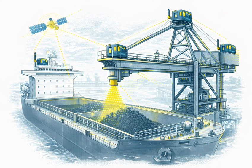
Ship loader and bulk cargo vessel with GPS monitoring units and sensor overlays illustrating controlled loading zones and engineering oversight under AS 4324.1

Understanding AS 4324.1 in a Brownfield Context

AS 4324.1 addresses mobile equipment used for continuous bulk handling, including:

  • Yard stackers and reclaimers
  • Bucket wheel reclaimers
  • Slewing and travelling machines
  • Ship loaders at export terminals

While the standard establishes a strong baseline for design and safety, many operating machines:

  • Pre-date the current revision of the standard
  • Have undergone multiple undocumented modifications
  • Operate under loading conditions that differ from original assumptions

In these situations, engineering judgement is required. Compliance becomes less about box-ticking and more about demonstrating that risks are understood, controlled, and managed over the asset lifecycle.


Common Challenges on Operating Mine Sites

Across coal handling plants, iron ore operations, and port facilities, several recurring issues emerge:

1. Incomplete or Outdated As-Built Information

Accurate geometry, slew limits, clearances, and structural interfaces are often unknown. This creates risk during upgrades and maintenance planning.

2. Fatigue and Structural Degradation

Large mobile machines experience cyclic loading across slewing, luffing, and travel motions. Fatigue cracking and unexpected failures require ongoing monitoring, not one-off assessments.

3. Access, Guarding, and Maintenance Compliance

Requirements evolve over time. Older machines may not meet current expectations for access systems, guarding, or safe maintenance practices.

4. Downtime Sensitivity

Stackers, reclaimers, and ship loaders are often production-critical assets. Upgrade windows are limited, and poor fit-up or rework can have significant commercial consequences.


Technology Supporting Modern Risk Management

While AS 4324.1 remains the foundation, modern technology allows asset owners to manage risk more effectivelyโ€”particularly on brownfield equipment.

GPS Positioning and Controlled Operating Zones

Where GPS positioning is enabled, defined operating zones can be established to:

  • Prevent interaction with stockpiles during rapid translation
  • Automatically reduce slew or travel speed in high-risk zones
  • Limit impact loads on critical components such as slew rings and fluffing gears

These systems are primarily productivity-driven, but they also reduce the likelihood of high-energy impacts that contribute to mechanical damage.


LiDAR Scanning as an Emerging Risk Layer

LiDAR scanning is not a replacement for traditional controls, and it is still evolving in this application. However, it can provide:

  • Accurate spatial awareness of surrounding structures
  • Verification of clearances and exclusion envelopes
  • A secondary risk-management layer supporting operator decision-making

When combined with engineering-led interpretation, LiDAR contributes to a layered risk approach rather than acting as a standalone safety system.


Condition Monitoring and Real Load Understanding

Accelerometers installed across a range of frequencies can deliver valuable insight into:

  • Actual operating loads
  • Dynamic response during slewing, reclaiming, and travel
  • Early indicators of fatigue-related issues

This data supports more informed maintenance decisions and provides evidence of how a machine is truly being usedโ€”often revealing load cases not considered in original designs.


Engineering-Led Compliance and Asset Life Extension

For brownfield assets, compliance with AS 4324.1 is best approached as a continuous engineering process, not a single milestone. This includes:

  • Accurate reality capture and digital models
  • Verification of clearances, interfaces, and structural geometry
  • Informed upgrade design that fits the first time
  • Risk-based decision-making supported by real operating data

This approach helps asset owners extend the life of critical machines while managing risk, performance, and availability.


How Hamilton By Design Supports Bulk Handling Assets

Hamilton By Design works with asset owners and engineering teams to support:

  • Brownfield upgrades of stackers, reclaimers, and ship loaders
  • Engineering-grade LiDAR scanning and as-built documentation
  • Fit-for-purpose mechanical design for modifications and life-extension
  • Independent engineering insight across OEM and site interfaces

Our focus is on engineering clarity, practical risk reduction, and minimising disruption to operations.


Talk to an Engineer About Your Asset

If you are planning a brownfield upgrade, life-extension, or risk review of mobile bulk-handling equipment, talk to an engineer at Hamilton By Design about how accurate data and practical engineering can support your next decision.

Hamilton By Design logo displayed on a blue tilted rectangle with a grey gradient background
3D LiDAR scanning and 3D modelling service button โ€” laser scanner capturing a point cloud for engineering and CAD modelling
Mechanical engineering services

Our clients:

Name
Would you like us to arrange a phone consultation for you?
Address
Finite Element Analysis (FEA) engineering simulation button
Mechanical engineering services

AS 1755 Conveyor Safety

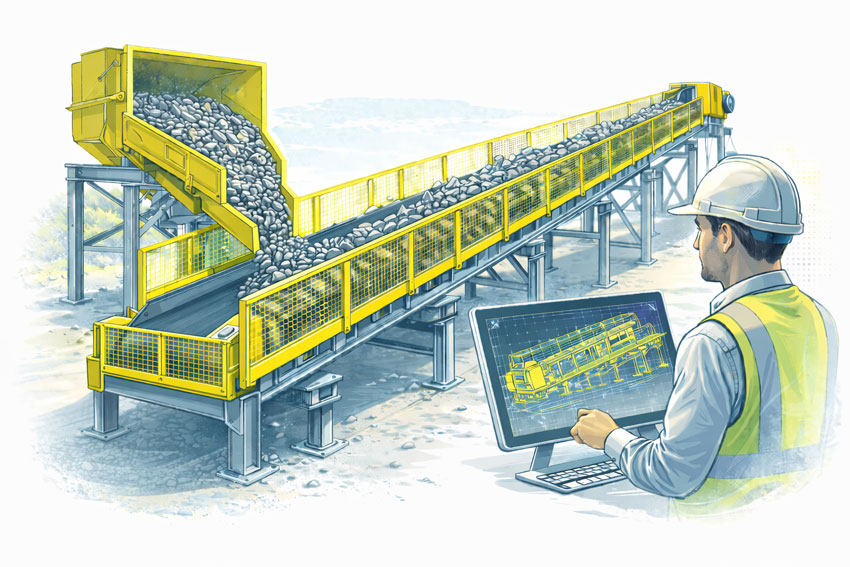
Engineer reviewing a guarded conveyor system with fixed side and nip-point guards designed to prevent access to moving parts.

Designing Conveyor Guarding for Compliance, Safety, and Practical Operation

Conveyors are widely used across processing, manufacturing, and materials-handling environments, but they also present some of the most persistent safety risks in industrial operations. Entrapment, nip points, rotating components, and maintenance access are all recognised hazards that must be managed through proper design and guarding.

In Australia, these risks are addressed through AS 1755 โ€“ Conveyors โ€“ Safety Requirements, which establishes the minimum safety expectations for conveyor systems across their full lifecycle, from design and installation through to operation and maintenance.

This article outlines what AS 1755 requires, why compliant conveyor guarding is critical, and how engineering-led design plays a key role in achieving practical safety outcomes.


Bulk materials conveyor with compliant safety guarding at the hopper, tail end, and along the conveyor, shown with an engineer reviewing guarding design drawings.
3D LiDAR scanning and 3D modelling service button โ€” laser scanner capturing a point cloud for engineering and CAD modelling
Mechanical engineering services

What Is AS 1755?

AS 1755 is the Australian Standard that defines safety requirements for belt conveyors and other conveyor systems. It addresses both new and existing installations and applies to conveyors used in industrial, commercial, and processing environments.

Rather than focusing on individual guarding components in isolation, AS 1755 considers the conveyor system as a whole, including how people interact with it during normal operation, inspection, cleaning, and maintenance.

The standard is referenced by regulators, safety professionals, and engineers as the primary benchmark for conveyor safety in Australia.


Key Safety Principles in AS 1755

AS 1755 is built around a number of core safety principles that influence how conveyor guarding should be designed.

These include eliminating hazards where possible, controlling remaining risks through engineering solutions, and ensuring that guarding does not introduce new risks by restricting access or encouraging unsafe behaviour.

In practice, this means that compliant guarding must be effective, durable, and suitable for the operating environment, while still allowing conveyors to be inspected, cleaned, and maintained safely.


Conveyor Guarding Requirements

A major focus of AS 1755 is the control of access to hazardous areas. This includes guarding of:
  • Drive pulleys and tail pulleys
  • Return rollers and idlers
  • Nip points and shear points
  • Rotating shafts and couplings
  • Chain drives, belt drives, and gearboxes

Guarding must be designed so that body parts cannot access hazardous zones, taking into account reach distances, openings, and the position of the conveyor relative to walkways or platforms.

Importantly, AS 1755 recognises that guarding must be fit for purpose. Poorly designed guards that are difficult to remove, inspect, or maintain are often bypassed or removed altogether, creating new safety risks.


Fixed Guards vs Interlocked Guards

AS 1755 allows for different types of guarding depending on the application and risk profile.

Fixed guards are commonly used where access is not required during normal operation. These guards must be securely fixed and require tools for removal.

Interlocked guards may be required where regular access is necessary. These systems ensure that the conveyor cannot operate while the guard is open or removed, reducing the risk of exposure to moving parts.

Selecting the appropriate guarding strategy requires an understanding of how the conveyor is used in practice, not just how it appears on drawings.


Existing Conveyors and Retrofit Challenges

Many conveyors currently in service were installed before the latest versions of AS 1755 were adopted. In these cases, compliance is often achieved through retrofit guarding rather than full replacement.

Retrofitting guarding to existing conveyors introduces additional challenges, including:

  • Limited space around existing equipment
  • Incomplete or outdated drawings
  • Structural constraints
  • Ongoing operation during upgrades

Engineering-led assessment and accurate documentation of existing conditions are critical when designing retrofit guarding solutions that comply with AS 1755 without disrupting operations.


The Role of Engineering in Conveyor Guarding Design

AS 1755 does not provide prescriptive โ€œone-size-fits-allโ€ guard designs. Instead, it sets performance requirements that must be interpreted and applied by competent professionals.

Engineering input is essential to ensure that conveyor guarding:

  • Addresses all relevant hazards
  • Integrates with existing mechanical and structural systems
  • Can be fabricated and installed accurately
  • Supports safe maintenance and inspection activities

Poorly engineered guarding may appear compliant on paper but fail in real-world use.


Documentation, Verification, and Ongoing Safety

Compliance with AS 1755 is not a one-time activity. Conveyor systems evolve over time as layouts change, equipment is upgraded, and operating practices shift.

Clear documentation of guarding design, installation, and assumptions provides a baseline for future modifications and safety reviews. This documentation is also critical when demonstrating due diligence to regulators or during incident investigations.


Why AS 1755 Matters

AS 1755 exists to prevent serious injuries and fatalities associated with conveyor systems. When applied correctly, it provides a structured framework for identifying hazards, implementing effective controls, and maintaining safe operation over the life of the equipment.

Achieving compliance requires more than installing mesh around moving parts. It requires understanding how people interact with conveyors and designing guarding that supports safe behaviour rather than working against it.


Hamilton By Design logo displayed on a blue tilted rectangle with a grey gradient background

Conveyor guarding designed in accordance with AS 1755 is a critical component of safe industrial operations. Engineering-led design, accurate documentation, and practical consideration of maintenance and operation are essential to achieving compliance that works in practice.

When conveyor safety is treated as an engineering problem rather than a checkbox exercise, the result is safer equipment, fewer incidents, and more reliable operations.

Manufacturing and production services button

Our clients


Name
Would you like us to arrange a phone consultation for you?
Address

3D CAD Modelling Australia service banner for Hamilton By Design


CHPP Engineering title graphic featuring bold white text reading "CHPP Engineering" centred on a blue rounded rectangle background.
Pipework Drafting title graphic featuring bold white text reading "Pipework Drafting" centred on a blue rounded rectangle background.
3D LiDAR Scanning for Engineering Projects title graphic featuring bold white text on a blue rounded rectangle background.


Finite Element Analysis (FEA) engineering simulation button
Structural drafting services button
Mechanical drafting services button


Australian Drafting logo featuring bold white text reading "Australian Drafting" centred on a blue rounded rectangle background.
Engineering Governance title graphic featuring bold white text reading "Engineering Governance" centred on a blue rounded rectangle background.
Engineering-Grade LiDAR Scanning title graphic featuring bold white text on a blue rounded rectangle background.


Mechanical drafting services button
Structural drafting services button


Fabrication and product design services
3D CAD Modelling Australia service banner for Hamilton By Design
Mechanical, Structural & Pipework Drafting service banner by Hamilton By Design featuring white text on a blue background.


3D LiDAR scanning and 3D modelling service button โ€” laser scanner capturing a point cloud for engineering and CAD modelling
Mechanical engineering services

Mechanical Engineering | Structural Engineering