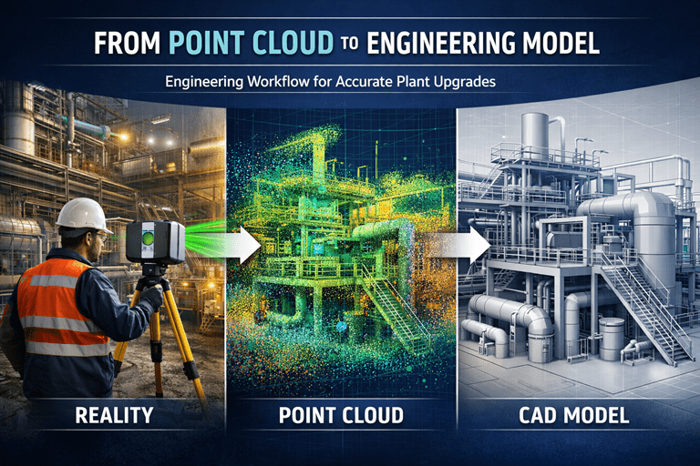
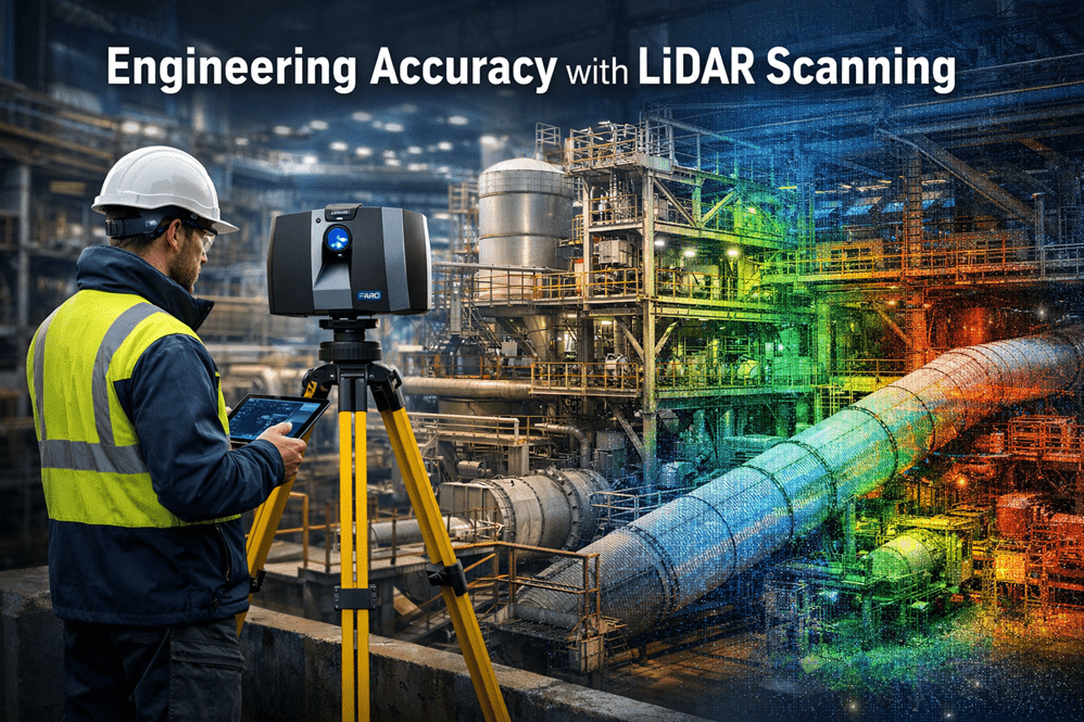
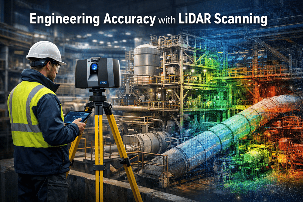
SolidWorks Point Cloud to CAD Workflow | From LiDAR Scans to Detailed Engineering Drawings

SolidWorks Workflow for Converting Point Cloud Data into Detailed Engineering Drawings

From Reality Capture to Fabrication Documentation

The rapid adoption of terrestrial LiDAR scanning and engineering-grade reality capture technologies has fundamentally changed the way engineering projects are executed. For decades, engineers, designers and BIM specialists have relied on traditional workflows that begin with conceptual layouts, survey control, architectural envelopes or predefined design models. Today, however, many industrial projects start with something entirely different: a point cloud.

Instead of beginning with assumptions about what exists, engineering teams can now begin with measured reality.

This shift has significant implications for how projects are planned, modelled and documented. It also raises an important discussion regarding the role of Building Information Modelling (BIM), top-down modelling techniques and traditional design workflows when accurate point cloud information is available from the outset.

While BIM remains a powerful methodology, reality capture introduces a different way of thinking that is particularly valuable for brownfield, industrial, mining, manufacturing and infrastructure projects.

The reality is that neither approach is universally better than the other.

As with most engineering decisions, it is often a case of horses for courses.


The Rise of Engineering-Grade Reality Capture

Modern terrestrial LiDAR scanners can capture millions of points every second, producing highly accurate three-dimensional representations of existing facilities.

These systems are now routinely used throughout:

  • Mining operations
  • Mineral processing plants
  • Smelters
  • Power stations
  • Water treatment facilities
  • Manufacturing plants
  • Commercial buildings
  • Hospitals
  • Transport infrastructure
  • Refineries

Unlike traditional survey methods that capture selected points, LiDAR scanning captures entire environments.

The resulting point cloud becomes a digital record of reality.

Engineers can then revisit the site virtually, long after the field work has been completed.

This offers significant advantages including:

  • Reduced site visits
  • Improved safety
  • Faster design development
  • Better clash detection
  • Enhanced stakeholder collaboration
  • Improved asset documentation
  • Accurate retrofit design

For industrial facilities where access may be restricted, hazardous or costly, point cloud data often becomes one of the most valuable project assets available.


Understanding Point Clouds

A point cloud is a collection of millions or billions of measured XYZ coordinates.

Each point represents a location in space.

When combined, these points create a highly detailed representation of physical objects including:

  • Structural steel
  • Pipework
  • Equipment
  • Conveyors
  • Tanks
  • Buildings
  • Mechanical components
  • Electrical services
  • Access systems

Modern scanners may also capture colour information, intensity data and imagery, creating a realistic digital twin of the physical environment.

Unlike traditional CAD models, point clouds contain measured information rather than designed information.

This distinction is important.

A CAD model represents what was intended.

A point cloud represents what actually exists.

For brownfield engineering projects this difference can be substantial.


Why Traditional BIM Workflows Can Struggle

Building Information Modelling originated primarily within the architectural and construction sectors.

The traditional BIM process generally follows a sequence such as:

Concept Design โ†’ Schematic Design โ†’ Detailed Design โ†’ Construction โ†’ Asset Management

The model evolves as the project progresses.

In many BIM workflows the process begins with an architectural envelope or predefined design geometry.

Walls, floors, columns and services are created within a structured modelling environment.

This approach works exceptionally well for:

  • New buildings
  • Greenfield developments
  • Commercial construction
  • Architectural projects
  • Civil infrastructure projects

However, industrial facilities rarely fit neatly into these categories.

A mining plant built over 40 years may contain:

  • Multiple undocumented modifications
  • Legacy equipment
  • Inaccurate drawings
  • Informal field changes
  • Missing records
  • Deformed structures
  • Equipment relocations

In these situations the design model is often less accurate than the physical asset itself.

This creates a challenge.

Traditional BIM workflows frequently assume the model is the primary source of truth.

Reality capture reverses that assumption.

The point cloud becomes the source of truth.

The model simply becomes a representation of measured reality.


Reality-First Engineering

A reality-first workflow begins with data acquisition rather than design assumptions.

The process typically follows:

  1. Site Scanning
  2. Point Cloud Registration
  3. Quality Assurance
  4. Point Cloud Optimisation
  5. Model Development
  6. Engineering Analysis
  7. Drawing Production
  8. Construction Documentation

Instead of asking:

“What should this facility look like?”

The workflow asks:

“What does this facility actually look like?”

This subtle change can significantly improve project outcomes.


SolidWorks and Point Cloud Modelling

SolidWorks has evolved into a powerful platform for working with reality capture data.

While originally developed as a mechanical design system, modern versions provide excellent capabilities for integrating scan data into engineering workflows.

Point clouds can be imported through various formats including:

  • E57
  • LAS
  • XYZ
  • PLY
  • STL
  • OBJ
  • Mesh formats

Depending on project requirements, the workflow may involve:

  • Direct point cloud reference
  • Mesh generation
  • Surface modelling
  • Parametric feature creation
  • Reverse engineering
  • Assembly development

The chosen approach depends on the intended deliverable.


The Importance of Top-Down Modelling

Top-down modelling becomes particularly valuable when working from point cloud data.

Traditional bottom-up modelling involves creating individual components separately before assembling them.

Top-down modelling reverses this process.

The assembly becomes the master model.

Individual components are then developed within the context of the larger system.

For industrial facilities this approach offers significant advantages.


Why Top-Down Modelling Works Well with Point Clouds

A point cloud already contains contextual information.

Pipework exists relative to equipment.

Equipment exists relative to structures.

Structures exist relative to buildings.

Everything already has a defined relationship.

Top-down modelling allows engineers to preserve these relationships.

For example:

A conveyor transfer chute may be modelled directly within the context of:

  • Existing conveyor structure
  • Existing walkways
  • Existing pipework
  • Existing electrical services
  • Existing maintenance access

The design develops within the reality captured environment.

This significantly reduces the risk of clashes.


Skeleton Models and Layout Control

One of the most effective top-down approaches involves the use of skeleton models.

A skeleton model contains:

  • Key reference geometry
  • Design planes
  • Centre lines
  • Control sketches
  • Interface locations

When working from point clouds, the skeleton model can be created directly from measured geometry.

This establishes a reliable framework for the remainder of the design.

Individual components then inherit relationships from the skeleton model.

Benefits include:

  • Improved consistency
  • Faster design changes
  • Better design intent control
  • Reduced assembly errors

Scan-to-CAD Workflow

A typical Scan-to-CAD workflow within SolidWorks may follow the following sequence.

Step 1 โ€“ Site Capture

Engineering-grade LiDAR scanning is completed on site.

Data is collected from multiple scanner positions.

The objective is to capture sufficient coverage while maintaining registration quality.


Step 2 โ€“ Registration

Individual scans are registered into a unified coordinate system.

This produces a complete point cloud.

Quality control is performed to verify registration accuracy.

Typical industrial projects may achieve overall accuracies within several millimetres.


Step 3 โ€“ Point Cloud Cleaning

Noise is removed.

Unwanted objects may be filtered.

Temporary equipment can be excluded.

The objective is to create a usable engineering dataset.


Step 4 โ€“ Import into Modelling Environment

The point cloud is imported into the modelling platform.

At this stage the cloud becomes a digital reference.

The cloud itself is generally not modified.

Instead, engineering geometry is created around it.


Step 5 โ€“ Create Reference Geometry

Reference planes, axes and coordinate systems are established.

These form the foundation of the modelling process.

Top-down methodologies become particularly valuable at this stage.


Step 6 โ€“ Build Parametric Models

Engineering components are modelled using parametric features.

Examples include:

  • Structural steel
  • Tanks
  • Pipework
  • Chutes
  • Platforms
  • Conveyors
  • Ductwork

The resulting model remains editable and fully configurable.


Step 7 โ€“ Validation

The model is compared against the point cloud.

Engineers verify fit, alignment and geometry.

Potential clashes are identified early.


Step 8 โ€“ Drawing Production

Detailed drawings are generated directly from the validated model.

Deliverables may include:

  • General arrangements
  • Fabrication drawings
  • Assembly drawings
  • Pipe spool drawings
  • Structural steel details
  • Installation drawings
  • Bill of materials

Reverse Engineering Using Point Clouds

Reverse engineering is one of the most powerful applications of reality capture.

Many industrial facilities contain components with:

  • Missing drawings
  • Obsolete equipment
  • Unknown suppliers
  • Legacy modifications

Point clouds provide a practical starting point.

Engineers can recreate:

  • Mechanical components
  • Structural systems
  • Pipework networks
  • Fabricated assemblies

The resulting CAD models become valuable engineering assets.


Parametric Models versus Mesh Models

A common mistake is assuming that a mesh model is equivalent to a CAD model.

It is not.

A mesh represents geometry.

A parametric model represents engineering intent.

This distinction is critical.

A parametric SolidWorks model allows:

  • Dimension changes
  • Configuration control
  • Design modifications
  • Manufacturing documentation
  • Finite element analysis

For most engineering applications, converting point clouds into intelligent parametric models provides significantly greater value than simply generating meshes.


Producing Detailed Engineering Drawings

Once a validated model exists, drawing production becomes straightforward.

SolidWorks can automatically generate:

  • Orthographic views
  • Sections
  • Detail views
  • Exploded views
  • Bills of materials
  • Weldment cut lists

This dramatically reduces drafting effort.

Because the drawings originate from the model, consistency is maintained throughout the project.


Brownfield Projects Benefit Most

The reality-first workflow delivers the greatest value in brownfield environments.

These include:

  • Operating mines
  • Smelters
  • Refineries
  • Processing plants
  • Manufacturing facilities
  • Water treatment plants

In these environments accurate existing-condition information is often more valuable than historic drawings.

A point cloud provides a measurable record of the asset as it exists today.


BIM versus Point Cloud Driven Engineering

This discussion is sometimes framed as:

“BIM versus Reality Capture.”

In practice this is the wrong question.

Reality capture and BIM should not be viewed as competing technologies.

They solve different problems.

BIM provides:

  • Information management
  • Design coordination
  • Asset lifecycle management
  • Construction planning
  • Facility management integration

Reality capture provides:

  • Existing-condition verification
  • Accurate geometry
  • Retrofit design support
  • Asset documentation
  • Digital twin creation

The most successful projects often combine both approaches.


A Modern Hybrid Workflow

Increasingly, engineering organisations are adopting a hybrid workflow.

The process becomes:

Reality Capture โ†’ Engineering Model โ†’ BIM Integration

Rather than creating BIM models based on assumptions, the BIM environment is populated using measured reality.

This approach improves confidence throughout the project lifecycle.

The BIM system benefits from more accurate geometry.

The engineering team benefits from reliable site information.

The asset owner benefits from better data quality.

Everybody wins.


The Future of Digital Engineering

The future of engineering is likely to become increasingly reality driven.

Advancements in:

  • LiDAR technology
  • Mobile scanning
  • Drone scanning
  • Artificial Intelligence
  • Automated feature extraction
  • Digital twins

will continue to accelerate the adoption of reality capture workflows.

However, traditional engineering principles remain essential.

Engineers still need to understand:

  • Design intent
  • Structural behaviour
  • Manufacturing processes
  • Construction methods
  • Asset management requirements

Technology provides information.

Engineering provides understanding.


SolidWorks provides an exceptionally capable platform for converting point cloud data into detailed engineering models and fabrication drawings. When combined with top-down modelling methodologies, point clouds become far more than visual references; they become the foundation of the engineering workflow.

Traditional BIM methodologies remain highly effective for greenfield projects and building-centric developments where the design model drives project delivery. However, in brownfield industrial environments the reality often differs from the original design documentation. In these situations, a point cloud frequently becomes the most accurate representation of the asset available.

Rather than viewing BIM and reality capture as competing philosophies, modern engineering teams should recognise the strengths of each approach. BIM excels at information management, coordination and lifecycle planning, while point cloud-driven workflows excel at capturing existing conditions and enabling accurate retrofit design.

Ultimately, the most effective solution is often a hybrid approach that combines the strengths of both. By starting with measured reality, developing intelligent parametric models in SolidWorks and integrating those models into broader BIM environments where appropriate, engineers can reduce risk, improve accuracy and deliver higher quality outcomes.

As digital engineering continues to evolve, the question is no longer whether point clouds should be used. The question is how effectively organisations can transform reality capture data into actionable engineering information that supports design, construction, operation and long-term asset management.

Hamilton By Design logo displayed on a blue tilted rectangle with a grey gradient background

Contact Us – Talk to Us

Name
Would you like us to arrange a phone consultation for you?
Address

Our Clients:
3D CAD Modelling Australia service banner for Hamilton By Design
3D LiDAR scanning and 3D modelling service button โ€” laser scanner capturing a point cloud for engineering and CAD modelling
Mechanical engineering services
3D CAD Modelling Australia service banner for Hamilton By Design
Mechanical, Structural & Pipework Drafting service banner by Hamilton By Design featuring white text on a blue background.
Australian Drafting logo featuring bold white text reading "Australian Drafting" centred on a blue rounded rectangle background.
Blue banner graphic displaying the text "Point Cloud to CAD - Australia" in large white lettering, representing point cloud processing, scan-to-CAD conversion and digital engineering services across Australia.
CHPP Engineering title graphic featuring bold white text reading "CHPP Engineering" centred on a blue rounded rectangle background.
Engineering Governance title graphic featuring bold white text reading "Engineering Governance" centred on a blue rounded rectangle background.
Mechanical engineering services
Australian Drafting logo featuring bold white text reading "Australian Drafting" centred on a blue rounded rectangle background.
3D LiDAR Scanning Hunter & Newcastle banner with white text on a blue background promoting engineering-grade laser scanning services for industrial, mining and infrastructure projects across the Hunter Valley and Newcastle region.
Mechanical Engineering Hunter & Newcastle banner promoting mechanical engineering services for mining, industrial plants, power generation, manufacturing and heavy industry throughout the Hunter Valley and Newcastle region.
Structural Drafting Hunter & Newcastle banner promoting structural drafting services for mining, industrial plants, power generation, manufacturing and infrastructure projects across the Hunter Valley and Newcastle region.
Mechanical Engineering Perth WA banner for Hamilton By Design featuring white text on a blue background.
3D Laser Scanning Perth WA banner for Hamilton By Design with white text on a blue background.
SolidWorks Perth WA banner for Hamilton By Design featuring white text on a blue background.
Fabrication and product design services
Finite Element Analysis (FEA) engineering simulation button
3D LiDAR scanning and 3D modelling service button โ€” laser scanner capturing a point cloud for engineering and CAD modelling
Blue rounded button with the text โ€œSolidWorks Designโ€ in white.
Mechanical drafting services button
Structural drafting services button

Mechanical Engineering | Structural Engineering


3D LiDAR Scanning Darwin for engineering surveys, laser scanning, reality capture and point cloud modelling services
3D LiDAR Scanning Australia engineering services for laser scanning, reality capture, scan-to-CAD, Scan-to-BIM and as-built documentation across Australia
3D LiDAR scanning services on the Central Coast providing engineering-grade laser scanning, point cloud capture, scan-to-CAD modelling and industrial reality capture for infrastructure and industrial projects.

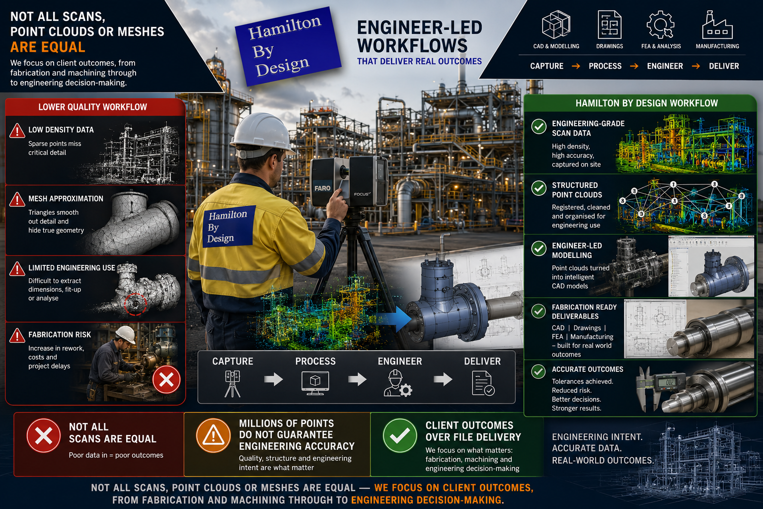
Not All Scans, Point Clouds or Meshes Are Equal โ€“ The Hamilton By Design Philosophy

Hamilton By Design engineer-led LiDAR scanning workflow showing engineering-grade point cloud capture, CAD modelling, fabrication-ready deliverables, and comparison between low-quality scans and structured engineering data

Based on a number of enquiries received this week, we thought it would be useful to clarify and streamline the Hamilton By Design philosophy regarding engineering-grade reality capture, drafting and engineering outcomes.

Not all scans are equal.

Not all point clouds are equal.

Not all meshes are equal.

One of the biggest misconceptions in industry is that once a point cloud has been generated, or once a mesh file or STL model has been created, the engineering work is complete. In reality, capturing a scan is only the beginning of the process.

The value does not come from simply obtaining a file.

The value comes from understanding the required outcome and ensuring the data collected is appropriate for that purpose.

At Hamilton By Design, we are engineer-led and provide engineering-grade scanning and reality capture services designed around the intended engineering outcome.

Whether you require outcomes associated with:

  • Fabrication and steel fit-up
  • Mechanical drafting
  • Reverse engineering
  • Plant modifications
  • Mechanical assemblies
  • Precision machining
  • Toolmaking
  • Engineering studies and analysis

our process begins by understanding the final requirement rather than assuming one scan methodology can satisfy every project.

Because different engineering outcomes require different levels of information.

A Scan Is Not the Final Product

Many discussions begin with questions such as:

“Can you provide a point cloud?”

“Can you create a mesh?”

“Can you provide an STL file?”

These are important questions; however, they often miss the larger engineering discussion.

The better question is:

What are you trying to achieve?

The same scan dataset may be used for several completely different purposes:

  • General plant layouts
  • Fabrication fit-up
  • Reverse engineering
  • Structural modifications
  • Mechanical assemblies
  • Existing condition verification
  • Bearing and shaft measurements
  • Precision tooling

The level of detail required for these outcomes can vary significantly.

A dataset that may be suitable for one application may be completely unsuitable for another.

Drafting Is More Than Drawing Lines

Modern industrial drafting has evolved considerably.

A capable draftsperson or designer should understand:

  • Point cloud datasets
  • Mesh and STL files
  • Scan quality and limitations
  • Measurable geometry development
  • CAD model generation
  • Manufacturing requirements
  • Installation requirements
  • Practical engineering considerations

The objective is not simply creating a drawing.

The objective is converting real-world conditions into useful engineering information.

Drafting Should Understand Manufacturing Reality

At Hamilton By Design we believe drafting extends beyond geometry displayed on a screen.

Strong design outcomes often come from understanding how components are actually manufactured, assembled and maintained.

Experience or understanding in areas such as:

  • Fabrication
  • Machining
  • Toolmaking
  • Manufacturing processes
  • Site installation
  • Plant maintenance

can significantly improve engineering decisions.

Understanding manufacturing realities affects:
  • Material selection
  • Weld access
  • Machining stock allowances
  • Tolerances
  • Assembly methods
  • Maintenance requirements
  • Manufacturing costs

A component may appear correct in CAD while still creating practical manufacturing issues.

Questions still need to be asked:

  • Can the component actually be manufactured?
  • Can welding equipment physically access the location?
  • Is sufficient machining stock available?
  • Can bearings be assembled correctly?
  • Can maintenance personnel access components?

Good drafting is not simply producing drawings.

Good drafting understands the complete journey from concept through to manufacture and operation.

Data Quality In = Data Quality Out

At Hamilton By Design we regularly work with:

  • Engineering-grade point clouds
  • Surface meshes
  • STL datasets
  • Reverse engineered components
  • Existing CAD models

One engineering principle remains consistent:

You cannot create information that was never captured.

Software may improve visual appearance and optimise workflows; however, software cannot accurately create missing information.

Examples include:

  • Higher point density generally captures more geometric detail
  • Lower point density captures less information
  • Reduced mesh resolution removes geometric definition
  • STL files can contain smoothing effects
  • Mesh reduction can remove critical engineering features

Reducing points reduces available information.

At some point, a measured representation becomes an approximation.

Bigger Data Sets Are Not Always Better

Many people assume larger datasets automatically create better outcomes.

The reality is there is a balance between detail and practicality.

Large datasets may increase:

  • Processing time
  • Storage requirements
  • Hardware demands
  • Registration effort
  • Modelling time
  • File management complexity
  • Project delivery time

The objective should not be creating the largest point cloud possible.

The objective should be collecting sufficient information to satisfy the engineering requirement.

Greater Accuracy Usually Comes With Greater Cost

Higher accuracy requirements typically require greater effort.

As required accuracy increases, additional work may include:

  • Increased point density
  • Larger point cloud datasets
  • Higher mesh resolution
  • Additional scan positions
  • Greater registration effort
  • Increased verification requirements
  • Additional modelling effort
  • More engineering review

As detail increases:
  • File sizes increase
  • Processing requirements increase
  • Engineering effort increases
  • Costs may increase

The objective should not be maximum data.

The objective should be the correct data.

One Project Can Contain Multiple Tolerances

One of the most common misunderstandings is assuming an entire project operates under one tolerance requirement.

Real engineering projects rarely operate this way.

Consider a pulley assembly.

The fabricated support structure, guards and mounting arrangement may comfortably operate within fabrication tolerances of:
Approximately ยฑ2 mm

However, the same assembly may also include:

  • Shaft diameters
  • Bearing journals
  • Keyways
  • Bearing fits
  • Machined interfaces

These features may require significantly tighter dimensional control.

Typical examples include:

Fabrication and steel fit-up
Approximately ยฑ2 mm

Machined components and mechanical interfaces
Approximately ยฑ0.1 mm

Precision tooling and specialised manufacturing
Potentially <0.1 mm

A fabricator and a toolmaker are not working to the same expectations.

Applying toolmaking tolerances to general fabrication may unnecessarily increase complexity and cost.

Likewise, applying fabrication assumptions to precision-machined components may create significant issues.

One mesh does not automatically solve every engineering requirement.

The Hamilton By Design Approach

At Hamilton By Design we work backwards from the final outcome.

Questions we commonly ask include:

  • Is the project for fabrication?
  • Is machining required?
  • Is reverse engineering required?
  • Is there a critical bearing or shaft interface?
  • Is this for plant modifications?
  • Is this for a precision component?
  • Is this for engineering studies?

These answers determine:

  • Scan methodology
  • Point cloud density
  • Registration strategy
  • Modelling approach
  • Verification requirements
  • Engineering effort
  • Final deliverables

We focus on providing the right information at the right level for the intended purpose.

Because engineering-grade scanning is not about creating the biggest point cloud.

Engineering-grade scanning is not about creating the largest mesh.

Engineering-grade scanning is about producing reliable information that supports real-world engineering outcomes.

Hamilton By Design logo displayed on a blue tilted rectangle with a grey gradient background

Our clients

3D LiDAR scanning and 3D modelling service button โ€” laser scanner capturing a point cloud for engineering and CAD modelling
Mechanical engineering services
Finite Element Analysis (FEA) engineering simulation button
Mechanical engineering services
Name
Would you like us to arrange a phone consultation for you?
Address
3D CAD Modelling Australia service banner for Hamilton By Design
Australian Drafting logo featuring bold white text reading "Australian Drafting" centred on a blue rounded rectangle background.
Engineering Governance title graphic featuring bold white text reading "Engineering Governance" centred on a blue rounded rectangle background.
Mechanical, Structural & Pipework Drafting service banner by Hamilton By Design featuring white text on a blue background.
Mechanical engineering services
Blue rounded button with the text โ€œSolidWorks Designโ€ in white.
Finite Element Analysis (FEA) engineering simulation button
3D LiDAR Scanning Darwin for engineering surveys, laser scanning, reality capture and point cloud modelling services
3D LiDAR Scanning Australia engineering services for laser scanning, reality capture, scan-to-CAD, Scan-to-BIM and as-built documentation across Australia
3D LiDAR scanning services on the Central Coast providing engineering-grade laser scanning, point cloud capture, scan-to-CAD modelling and industrial reality capture for infrastructure and industrial projects.
3D LiDAR Scanning Perth for engineering surveys, laser scanning, reality capture and point cloud modelling services
3D LiDAR Scanning Sydney for engineering surveys, laser scanning, reality capture and point cloud modelling services
3D LiDAR Scanning Brisbane for engineering surveys, laser scanning, reality capture and point cloud modelling services
3D LiDAR Scanning Canberra for engineering surveys, laser scanning, reality capture and point cloud modelling services
3D LiDAR Scanning Newcastle for engineering surveys, laser scanning, reality capture and point cloud modelling services
3D LiDAR Scanning Adelaide for engineering surveys, laser scanning, reality capture and point cloud modelling services

LiDAR vs Photogrammetry for Industrial Engineering

Engineering comparison of LiDAR scanning and photogrammetry used for capturing industrial plants and infrastructure.

Understanding the Difference Between LiDAR and Photogrammetry

When engineers need to capture accurate measurements of industrial infrastructure, two technologies are commonly considered: LiDAR scanning and photogrammetry.

Both methods allow engineers to create 3D digital models of real-world environments. However, when comparing LiDAR vs photogrammetry, each technology has different strengths depending on the type of engineering project.

For industries such as mining, processing plants, and heavy industrial facilities, choosing the right technology can significantly affect the accuracy, speed, and reliability of engineering design work.

At Hamilton By Design, LiDAR scanning is frequently used to capture existing conditions in complex industrial environments where precision is critical.

Learn more about engineering-grade scanning here:
https://www.hamiltonbydesign.com.au/home/engineering-grade-3d-laser-scanning-mining-industrial/


What is LiDAR Scanning?

LiDAR (Light Detection and Ranging) uses laser pulses to measure the distance between the scanner and surrounding surfaces. A terrestrial laser scanner emits millions of laser pulses per second and records the returned signal to calculate precise spatial coordinates.

The result is a dense 3D point cloud representing the scanned environment.

Engineering-grade LiDAR scanners commonly achieve millimetre-level accuracy, making them well suited for capturing industrial infrastructure such as:

  • pipework systems
  • structural steel
  • conveyors
  • tanks and vessels
  • pump stations
  • processing equipment

LiDAR scanning is widely used for plant upgrades, shutdown planning, and mechanical design where accurate site data is essential.

More information on LiDAR scanning services:
https://www.hamiltonbydesign.com.au/home/engineering-services/3d-laser-scanning/


What is Photogrammetry?

Photogrammetry is a technique that creates 3D models using photographs captured from multiple angles. Specialised software analyses overlapping images and reconstructs a three-dimensional model of the scene.

Photogrammetry is commonly used in:

  • aerial mapping
  • surveying large land areas
  • construction progress monitoring
  • environmental mapping
  • drone-based inspections

Because the technique relies on photographs rather than laser measurements, the accuracy of photogrammetry depends on factors such as image quality, lighting conditions, and camera calibration.


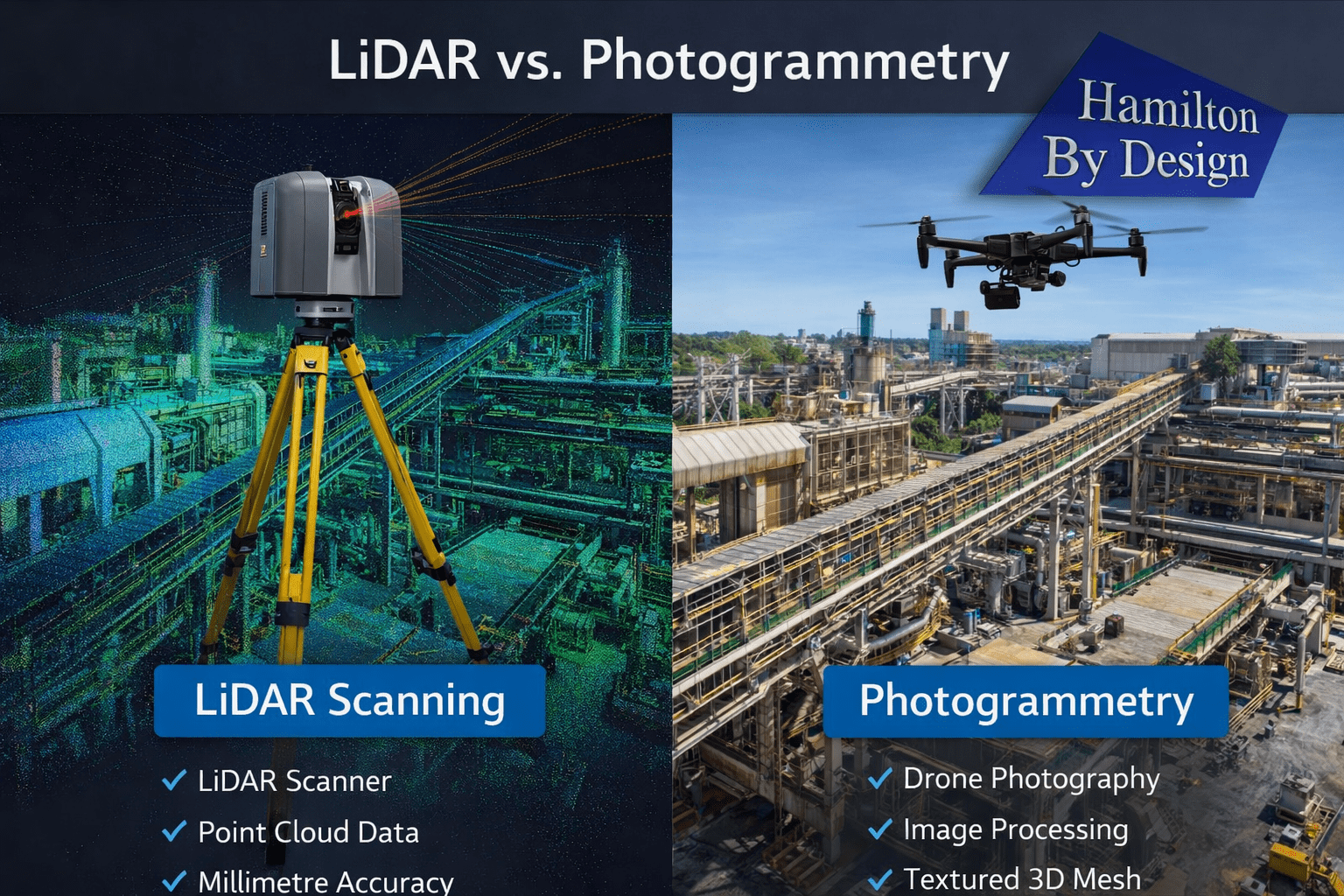
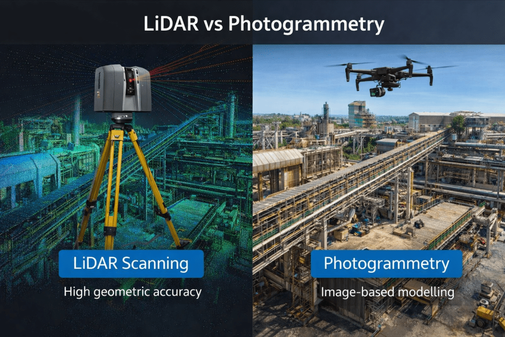
Comparison between LiDAR scanning and photogrammetry capturing an industrial engineering facility for 3D modelling.

LiDAR vs Photogrammetry: Key Differences

When comparing LiDAR vs photogrammetry, the main differences relate to measurement accuracy, speed of data capture, and suitability for complex environments.

FeatureLiDAR ScanningPhotogrammetry
Measurement MethodLaser distance measurementImage-based reconstruction
Typical AccuracyMillimetre-levelCentimetre-level (depending on conditions)
Performance in Low LightExcellentLimited
Surface DetailHigh geometric accuracyHigh visual detail
Performance in Complex PlantVery strongMore challenging
Data Capture SpeedVery fastModerate

For industrial engineering projects, LiDAR scanning typically provides more reliable geometric data, especially when scanning dense plant environments.


When LiDAR is Preferred in Industrial Engineering

LiDAR scanning is often the preferred technology for projects involving complex infrastructure.

Common engineering applications include:

  • plant upgrades and retrofits
  • pipework modifications
  • structural steel design
  • conveyor and materials handling systems
  • pump installations
  • shutdown planning

In these environments, millimetre-level accuracy is required to ensure new components fit correctly within existing structures.

LiDAR scanning is also effective in environments with limited lighting or reflective metal surfaces, which are common in industrial facilities.

You can read more about how engineers capture existing conditions before plant upgrades here:
https://www.hamiltonbydesign.com.au/capture-existing-conditions-before-plant-upgrades/


LiDAR scanning survey across Australia with engineer capturing industrial site data

When Photogrammetry is Useful

Photogrammetry remains a valuable tool for certain types of projects, particularly where large areas must be captured quickly.

Typical applications include:

  • drone-based terrain mapping
  • stockpile measurement
  • topographic surveys
  • construction progress documentation
  • infrastructure inspections

In these situations, photogrammetry provides an efficient method of capturing large datasets using aerial imagery.

However, for detailed industrial modelling, additional processing may be required to achieve the level of precision needed for engineering design.


Combining LiDAR and Photogrammetry

In some projects, engineers combine LiDAR scanning with photogrammetry to capture both accurate geometry and high-quality visual textures.

This approach can be useful when:

  • documenting heritage structures
  • visualising infrastructure for presentations
  • creating digital twins of facilities

However, for most industrial engineering applications, LiDAR scanning remains the primary technology used for accurate measurement.


From Scan Data to Engineering Models

Regardless of the capture method used, the final goal in engineering projects is often to convert the captured data into usable CAD models.

The typical workflow includes:

  1. Site data capture
  2. Data processing and alignment
  3. Point cloud generation
  4. Engineering modelling in CAD software
  5. Design and fabrication documentation

You can learn more about this process here:

Hamilton By Design logo displayed on a blue tilted rectangle with a grey gradient background

Conclusion

When comparing LiDAR vs photogrammetry, both technologies offer valuable tools for capturing real-world environments.

However, for most industrial engineering applications where accuracy and reliability are critical, LiDAR scanning typically provides the best results.

For mining, processing plants, and heavy industrial facilities, engineering-grade LiDAR scanning allows project teams to work from highly accurate digital models of existing infrastructure.

This improves design confidence, reduces installation risk, and helps ensure that new components integrate successfully with existing plant systems.

Hamilton By Design provides engineering-grade LiDAR scanning services to support industrial engineering projects across Australia.

3D LiDAR scanning and 3D modelling service button โ€” laser scanner capturing a point cloud for engineering and CAD modelling
Mechanical engineering services
Name
Would you like us to arrange a phone consultation for you?
Address
3D CAD Modelling Australia service banner for Hamilton By Design

Mechanical Engineering | Structural Engineering

3D LiDAR Scanning Darwin for engineering surveys, laser scanning, reality capture and point cloud modelling services
3D LiDAR Scanning Australia engineering services for laser scanning, reality capture, scan-to-CAD, Scan-to-BIM and as-built documentation across Australia
3D LiDAR scanning services on the Central Coast providing engineering-grade laser scanning, point cloud capture, scan-to-CAD modelling and industrial reality capture for infrastructure and industrial projects.
3D LiDAR Scanning Perth for engineering surveys, laser scanning, reality capture and point cloud modelling services
3D LiDAR Scanning Sydney for engineering surveys, laser scanning, reality capture and point cloud modelling services
3D LiDAR Scanning Brisbane for engineering surveys, laser scanning, reality capture and point cloud modelling services
3D LiDAR Scanning Canberra for engineering surveys, laser scanning, reality capture and point cloud modelling services
3D LiDAR Scanning Newcastle for engineering surveys, laser scanning, reality capture and point cloud modelling services
3D LiDAR Scanning Adelaide for engineering surveys, laser scanning, reality capture and point cloud modelling services

More Reading โ€“ Engineering Articles and Technical Resources

Engineer using a laser scanner capturing an industrial facility, converting scan data into a point cloud and engineering CAD model.

At Hamilton By Design, we regularly publish articles about engineering workflows, plant upgrades, LiDAR scanning, mechanical design, and industrial infrastructure.

We also contribute to technical discussions and engineering blogs that explore topics such as point cloud modelling, SolidWorks design, pipework detailing, and mining infrastructure upgrades.

This page provides a collection of additional technical reading and external resources related to engineering design and digital engineering workflows.

These articles complement the work we do at Hamilton By Design and may be useful for engineers, project managers, designers, and plant operators involved in industrial and mining infrastructure projects.


Industrial engineer operating a LiDAR laser scanner capturing high-accuracy point cloud data of a processing plant for engineering design and infrastructure upgrades.

Pipework Detailing and SolidWorks Design

One area where modern digital workflows are particularly valuable is pipework detailing and fabrication drawing development.

By combining LiDAR scanning with SolidWorks modelling, engineers can capture the true geometry of existing plant infrastructure and develop accurate pipe spool drawings for fabrication and installation.

The following article explores how laser scanning data can be used to support this workflow:

From Laser Scan to Pipe Spool Drawings โ€“ Using SolidWorks and LiDAR Data for Accurate Pipework Design

https://pipeworkdetailing.blogspot.com/2026/03/from-laser-scan-to-pipe-spool-drawings.html

This article discusses how engineering teams can move from capturing plant geometry with LiDAR scanning through to generating pipe spool drawings for fabrication.


LiDAR Scanning and Engineering Design Workflows

Laser scanning is increasingly used across industrial and mining projects to capture existing plant conditions before upgrades or modifications begin.

At Hamilton By Design we use engineering-grade LiDAR scanning to support:

โ€ข Mining infrastructure upgrades
โ€ข Industrial plant modifications
โ€ข Mechanical equipment installations
โ€ข Structural steel design
โ€ข Pipework routing and detailing
โ€ข Shutdown engineering projects

By converting scan data into engineering models, design teams can work directly against the true geometry of the plant environment.


You may also find the following articles useful:

Engineering Grade 3D Laser Scanning for Mining and Industrial Projects
https://www.hamiltonbydesign.com.au/home/engineering-grade-3d-laser-scanning-mining-industrial/

3D Laser Scanning Across Australia
https://www.hamiltonbydesign.com.au/home/engineering-services/3d-laser-scanning/3d-laser-scanning-across-australia/

3D Laser Scanning for Mining Plant Upgrades
https://www.hamiltonbydesign.com.au/engineering-grade-3d-laser-scanning-mining-plant-upgrades/

3D Laser Scanning for Mining Shutdown Projects
https://www.hamiltonbydesign.com.au/3d-laser-scanning-mining-shutdowns/

Capture Existing Conditions Before Plant Upgrades
https://www.hamiltonbydesign.com.au/capture-existing-conditions-before-plant-upgrades/

Point Cloud to Engineering Model Workflow
https://www.hamiltonbydesign.com.au/point-cloud-to-engineering-model-workflow/


Why We Share Additional Engineering Reading

Engineering projects often benefit from a combination of practical field knowledge, digital modelling workflows, and collaboration across the engineering community.

By sharing additional articles and resources, we hope to contribute to ongoing discussions about:

โ€ข Engineering measurement and accuracy
โ€ข Digital engineering workflows
โ€ข Mining infrastructure design
โ€ข Mechanical and structural modelling
โ€ข Industrial plant upgrades

If you are interested in discussing engineering-grade 3D laser scanning, mechanical engineering design, or infrastructure upgrades, please feel free to contact Hamilton By Design.

3D LiDAR scanning and 3D modelling service button โ€” laser scanner capturing a point cloud for engineering and CAD modelling
Mechanical engineering services
Name
Would you like us to arrange a phone consultation for you?
Address
3D CAD Modelling Australia service banner for Hamilton By Design

Accuracy of LiDAR Scanning for Engineering Applications

Industrial engineer operating a LiDAR laser scanner capturing high-accuracy point cloud data of a processing plant for engineering design and infrastructure upgrades.

Modern engineering projects increasingly rely on accurate digital representations of existing infrastructure before design, fabrication, or modification begins. One of the most powerful technologies enabling this is LiDAR scanning (Light Detection and Ranging).

At Hamilton By Design, LiDAR scanning is used to capture engineering-grade point cloud data of industrial facilities, mining infrastructure, processing plants, and mechanical systems across Australia.

Understanding the accuracy of LiDAR scanning is essential for engineers, project managers, and asset owners when planning upgrades or modifications to existing facilities.


LiDAR scanning of industrial infrastructure with a 3D point cloud overlay showing engineering-grade measurement accuracy.

What is LiDAR Scanning?

LiDAR scanning works by emitting thousands of laser pulses per second. These pulses strike surrounding surfaces and return to the scanner, allowing precise calculation of distance.

The result is a dense three-dimensional point cloud that captures the exact geometry of an environment.

This digital dataset can then be used for:

โ€ข Engineering modelling
โ€ข Plant layout verification
โ€ข Clash detection
โ€ข Structural analysis
โ€ข Reverse engineering
โ€ข Retrofit design

At Hamilton By Design, these datasets are commonly converted into engineering models and SolidWorks design geometry using our established workflow.

Learn more about this process here:

Point Cloud to Engineering Model Workflow
https://www.hamiltonbydesign.com.au/point-cloud-to-engineering-model-workflow/


Typical Accuracy of Engineering LiDAR Scanning

The accuracy of LiDAR scanning depends on several factors including the scanner type, range to the object, scanning environment, and control methodology.

Typical engineering-grade terrestrial LiDAR systems achieve:

ParameterTypical Accuracy
Scanner measurement accuracyยฑ1 mm to ยฑ3 mm
Registered scan network accuracyยฑ2 mm to ยฑ6 mm
Large plant scan accuracyยฑ5 mm to ยฑ10 mm

For most industrial engineering applications, this level of accuracy is more than sufficient to support:

โ€ข Structural steel modifications
โ€ข Pipework routing and tie-ins
โ€ข Mechanical equipment installation
โ€ข Conveyor and materials handling upgrades
โ€ข Plant shutdown engineering works


Factors That Affect LiDAR Accuracy

Although LiDAR scanning can achieve extremely high accuracy, several practical factors influence final results.

Scan Resolution

Higher resolution scanning increases the number of measured points and improves detail, but also increases processing time and file size.

Distance to Target

Accuracy decreases slightly as the distance between the scanner and the object increases. Industrial scanning programs typically maintain distances between 5โ€“40 metres.

Scan Registration

Multiple scans must be aligned together to form a complete dataset. Proper registration and survey control ensures that the final point cloud remains accurate across large areas.

Surface Conditions

Highly reflective, transparent, or moving surfaces may introduce noise or missing data within the scan.


Why Accuracy Matters for Engineering Projects

Engineering projects often involve modifying existing assets that may have been constructed decades ago.

Original drawings may be missing, outdated, or inaccurate.

By capturing true existing conditions, LiDAR scanning reduces risk during design and construction.

Benefits include:

โ€ข Reduced site rework
โ€ข Fewer installation clashes
โ€ข Faster shutdown execution
โ€ข Improved fabrication accuracy
โ€ข Reduced project uncertainty

This is why many engineering teams now perform scanning before commencing plant upgrades.

Capture Existing Conditions Before Plant Upgrades
https://www.hamiltonbydesign.com.au/capture-existing-conditions-before-plant-upgrades/


LiDAR Scanning for Mining and Industrial Infrastructure

Industries where LiDAR scanning is particularly valuable include:

โ€ข Mining and mineral processing
โ€ข Water and wastewater facilities
โ€ข Power generation plants
โ€ข Heavy manufacturing facilities
โ€ข Materials handling systems

At Hamilton By Design, scanning is commonly used to support:

โ€ข Shutdown planning
โ€ข Structural modifications
โ€ข Mechanical equipment upgrades
โ€ข Brownfield engineering projects

Learn more about our scanning services across Australia:

Engineering Grade 3D Laser Scanning for Mining and Industrial Projects
https://www.hamiltonbydesign.com.au/home/engineering-grade-3d-laser-scanning-mining-industrial/


From Scan Data to Engineering Design

Once captured, LiDAR data becomes the foundation for digital engineering workflows.

Point clouds can be converted into:

โ€ข SolidWorks models
โ€ข Structural steel models
โ€ข Pipe routing layouts
โ€ข Mechanical equipment models
โ€ข Digital twins of plant infrastructure

This allows engineers to design modifications directly against the existing environment, dramatically reducing project risk.


Hamilton By Design logo displayed on a blue tilted rectangle with a grey gradient background

Conclusion

LiDAR scanning has become an essential tool for modern engineering projects, providing millimetre-level accuracy when capturing existing infrastructure.

When combined with experienced engineering workflows, LiDAR enables faster, safer, and more reliable plant upgrades.

At Hamilton By Design, we specialise in transforming high-accuracy LiDAR data into practical engineering models and design solutions for mining, industrial, and infrastructure projects.


Need LiDAR Scanning for Your Project?

Hamilton By Design provides engineering-grade 3D laser scanning services across Australia to support plant upgrades, shutdown projects, and infrastructure modifications.

Learn more about our services here:

3D LiDAR scanning and 3D modelling service button โ€” laser scanner capturing a point cloud for engineering and CAD modelling
Mechanical engineering services
Name
Would you like us to arrange a phone consultation for you?
Address
3D CAD Modelling Australia service banner for Hamilton By Design
Australian Drafting logo featuring bold white text reading "Australian Drafting" centred on a blue rounded rectangle background.
Engineering Governance title graphic featuring bold white text reading "Engineering Governance" centred on a blue rounded rectangle background.
Mechanical, Structural & Pipework Drafting service banner by Hamilton By Design featuring white text on a blue background.
Mechanical engineering services
Blue rounded button with the text โ€œSolidWorks Designโ€ in white.
Finite Element Analysis (FEA) engineering simulation button
3D LiDAR Scanning Darwin for engineering surveys, laser scanning, reality capture and point cloud modelling services
3D LiDAR Scanning Australia engineering services for laser scanning, reality capture, scan-to-CAD, Scan-to-BIM and as-built documentation across Australia
3D LiDAR scanning services on the Central Coast providing engineering-grade laser scanning, point cloud capture, scan-to-CAD modelling and industrial reality capture for infrastructure and industrial projects.
3D LiDAR Scanning Perth for engineering surveys, laser scanning, reality capture and point cloud modelling services
3D LiDAR Scanning Sydney for engineering surveys, laser scanning, reality capture and point cloud modelling services
3D LiDAR Scanning Brisbane for engineering surveys, laser scanning, reality capture and point cloud modelling services
3D LiDAR Scanning Canberra for engineering surveys, laser scanning, reality capture and point cloud modelling services
3D LiDAR Scanning Newcastle for engineering surveys, laser scanning, reality capture and point cloud modelling services
3D LiDAR Scanning Adelaide for engineering surveys, laser scanning, reality capture and point cloud modelling services

Mining Infrastructure Design Discussions โ€“ SolidWorks and Industrial Engineering

Engineering workflow showing industrial laser scanning, point cloud data, and a CAD model used for plant upgrade design.

Modern mining and industrial infrastructure projects increasingly rely on advanced digital engineering tools to support plant design, equipment upgrades, and infrastructure development. Engineers working in mining environments must often design and model complex systems including materials handling equipment, processing plant infrastructure, and structural steel frameworks.

Engineer using a laser scanner capturing an industrial facility, converting scan data into a point cloud and engineering CAD model.

One of the most commonly used design platforms for mechanical engineering and plant infrastructure modelling is SolidWorks, which allows engineers to develop detailed 3D assemblies and fabrication-ready engineering drawings.

At Hamilton By Design, many projects involve the integration of modern digital engineering workflows with practical industry experience. These workflows often include:

  • Mechanical design for mining infrastructure
  • Bulk materials handling system design
  • Industrial plant layout modelling
  • Point cloud modelling from laser scanning
  • Engineering design for plant upgrades and shutdown projects

Engineering Design in Mining Infrastructure

Mining infrastructure often includes complex systems such as conveyors, transfer stations, processing equipment, and plant structures. Designing or upgrading these systems requires accurate modelling of both existing infrastructure and proposed modifications.

Modern engineering teams frequently combine several technologies during the design process, including:

  • 3D laser scanning to capture existing plant conditions
  • Point cloud modelling to represent real-world infrastructure
  • CAD modelling using platforms such as SolidWorks
  • Engineering drawings and documentation for fabrication and construction

These tools allow engineers to develop more accurate designs and reduce risks when implementing plant modifications or shutdown upgrades.


Engineering Discussions and SolidWorks Design Examples

Engineering professionals often share practical insights, modelling approaches, and design workflows through technical blogs and engineering discussion platforms.

For those interested in SolidWorks modelling techniques, mining infrastructure design concepts, and materials handling engineering, additional discussions can be found on the following engineering blog:

Mining Infrastructure โ€“ SolidWorks Design
https://mininginfrastructuresolidworksdesign.blogspot.com/

The blog explores various topics including mechanical design workflows, industrial equipment modelling, and practical engineering approaches used when designing plant infrastructure.


Supporting Mining Engineering Projects

Hamilton By Design supports mining and industrial operators with engineering services that include mechanical design, infrastructure modelling, and reality capture technologies such as laser scanning.

Learn more about our engineering-grade scanning and modelling services:

Engineering-Grade 3D Laser Scanning for Mining and Industrial Projects
https://www.hamiltonbydesign.com.au/home/engineering-grade-3d-laser-scanning-mining-industrial/

3D Laser Scanning Across Australia
https://www.hamiltonbydesign.com.au/home/engineering-services/3d-laser-scanning/3d-laser-scanning-across-australia/

Capturing Existing Conditions Before Plant Upgrades
https://www.hamiltonbydesign.com.au/capture-existing-conditions-before-plant-upgrades/


3D LiDAR scanning and 3D modelling service button โ€” laser scanner capturing a point cloud for engineering and CAD modelling
Mechanical engineering services

Engineering Knowledge Sharing

Engineering blogs and technical discussion platforms provide an opportunity for engineers, designers, and industry professionals to share knowledge about real-world engineering challenges.

By combining practical industry experience with modern digital engineering tools, the mining and industrial sectors continue to improve the way infrastructure is designed, documented, and upgraded.

For more engineering discussions on SolidWorks design and mining infrastructure modelling, visit:

https://mininginfrastructuresolidworksdesign.blogspot.com

3D CAD Modelling Australia service banner for Hamilton By Design
Australian Drafting logo featuring bold white text reading "Australian Drafting" centred on a blue rounded rectangle background.
Engineering Governance title graphic featuring bold white text reading "Engineering Governance" centred on a blue rounded rectangle background.
Mechanical, Structural & Pipework Drafting service banner by Hamilton By Design featuring white text on a blue background.
Mechanical engineering services
Blue rounded button with the text โ€œSolidWorks Designโ€ in white.
Finite Element Analysis (FEA) engineering simulation button
3D LiDAR Scanning Darwin for engineering surveys, laser scanning, reality capture and point cloud modelling services
3D LiDAR Scanning Australia engineering services for laser scanning, reality capture, scan-to-CAD, Scan-to-BIM and as-built documentation across Australia
3D LiDAR scanning services on the Central Coast providing engineering-grade laser scanning, point cloud capture, scan-to-CAD modelling and industrial reality capture for infrastructure and industrial projects.
3D LiDAR Scanning Perth for engineering surveys, laser scanning, reality capture and point cloud modelling services
3D LiDAR Scanning Sydney for engineering surveys, laser scanning, reality capture and point cloud modelling services
3D LiDAR Scanning Brisbane for engineering surveys, laser scanning, reality capture and point cloud modelling services
3D LiDAR Scanning Canberra for engineering surveys, laser scanning, reality capture and point cloud modelling services
3D LiDAR Scanning Newcastle for engineering surveys, laser scanning, reality capture and point cloud modelling services
3D LiDAR Scanning Adelaide for engineering surveys, laser scanning, reality capture and point cloud modelling services