Prineville, Oregon has a long industrial history built around timber, forestry, sawmills, and manufacturing. While the region is now recognised internationally for technology infrastructure and data centres, the timber and wood processing industries continue to play a major role in the local economy and industrial landscape.
Across sawmills, woodworking facilities, manufacturing plants, and industrial operations, companies are under increasing pressure to improve safety, reduce downtime, modernise aging infrastructure, and maintain accurate engineering documentation.
This is where Hamilton By Design Co. can assist.
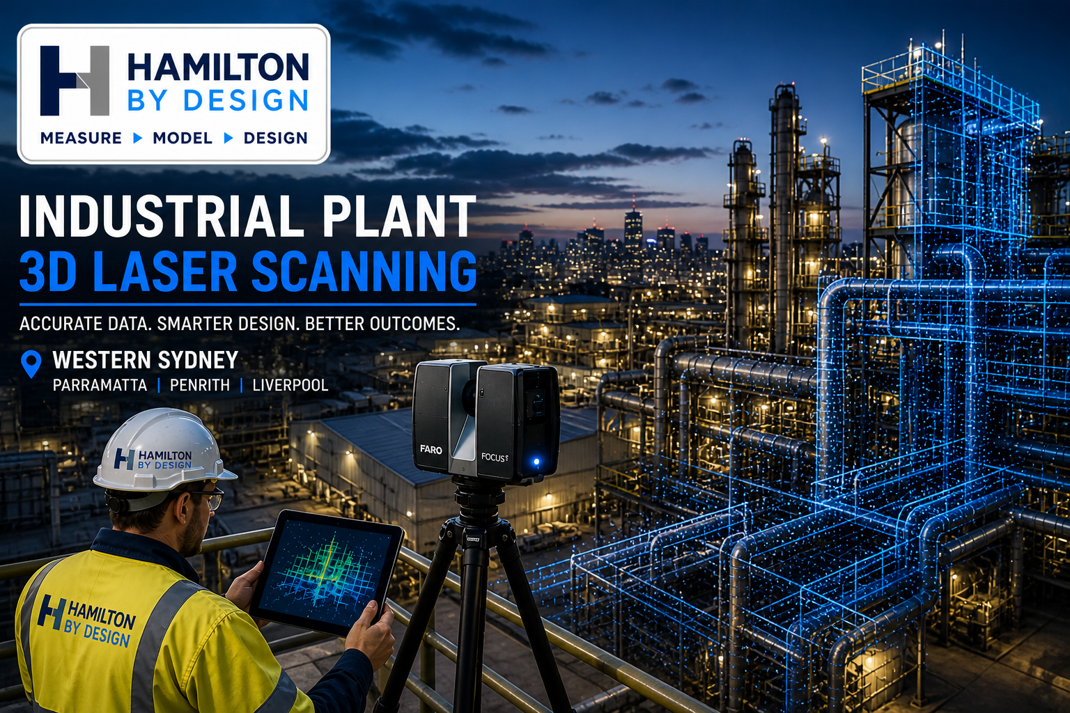
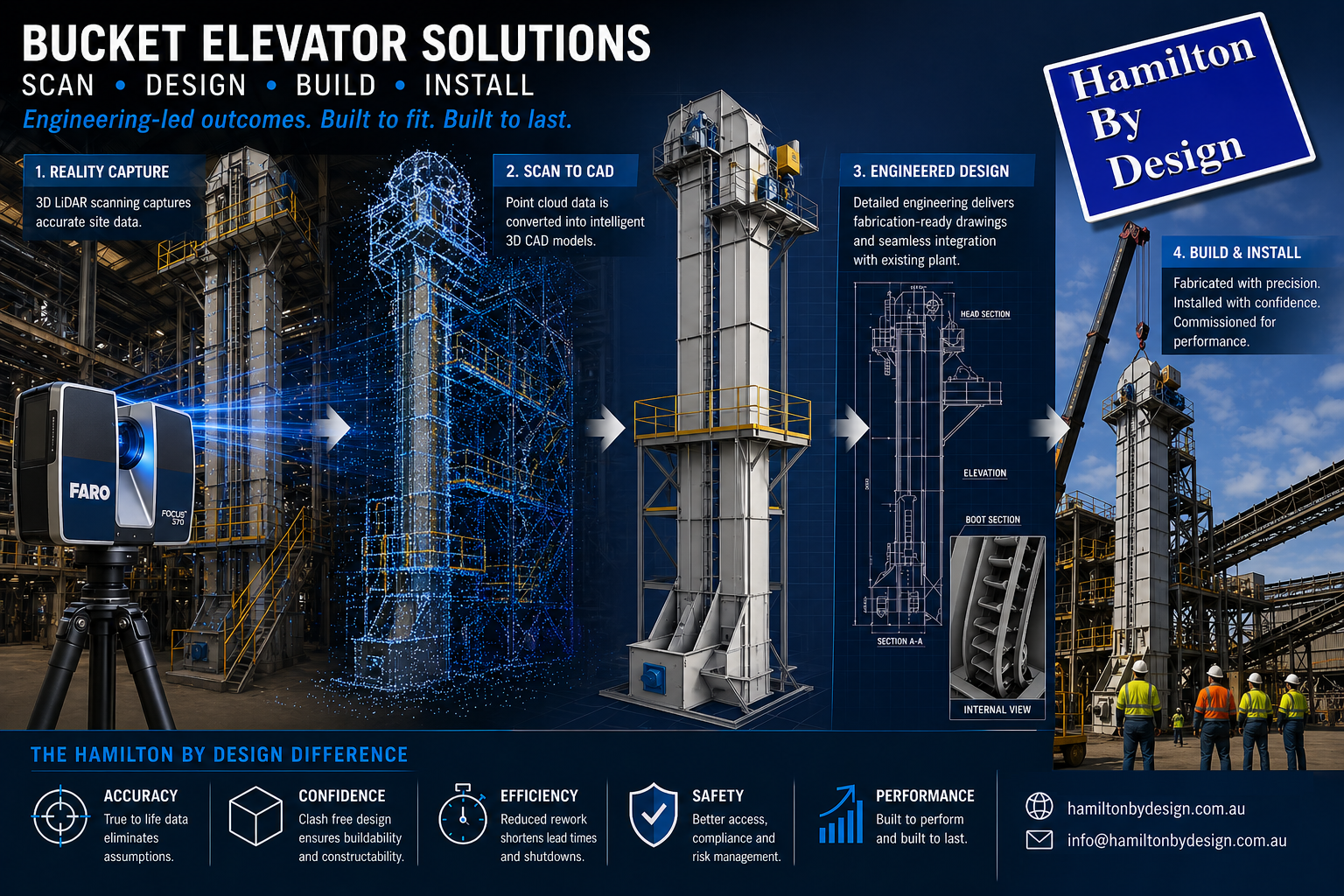
Hamilton By Design Co. provides engineer-led 3D LiDAR scanning, scan-to-CAD services, structural drafting, mechanical engineering support, and industrial digital engineering workflows for timber processing facilities, woodworking operations, industrial plants, and manufacturing infrastructure.
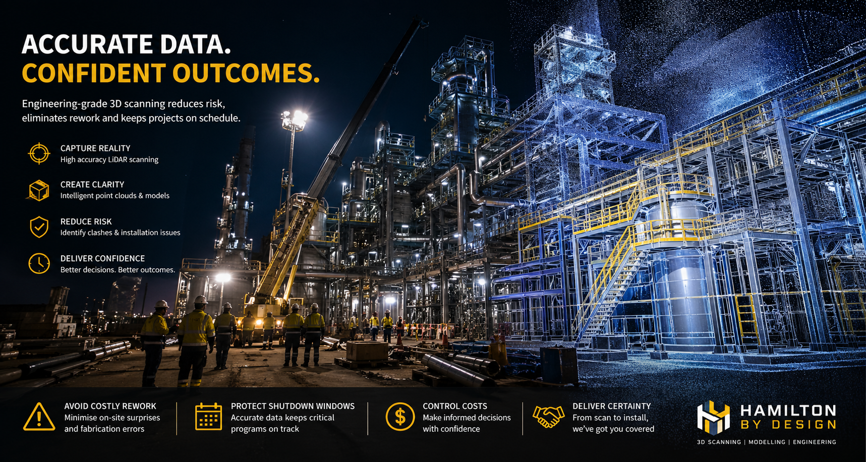
By combining engineering knowledge with high-accuracy terrestrial LiDAR scanning technology, Hamilton By Design helps companies reduce project risk, improve fabrication accuracy, and develop reliable as-built documentation for maintenance, shutdowns, plant upgrades, and future expansion projects.
Many timber mills and woodworking facilities contain highly mechanical environments involving:
- conveyors,
- transfer systems,
- saw lines,
- material handling systems,
- dust extraction infrastructure,
- hydraulic equipment,
- structural steel platforms,
- rotating machinery,
- and processing equipment.
Over decades of operation, many industrial facilities evolve through ongoing modifications, maintenance activities, and equipment replacements. In many cases, original drawings no longer reflect actual onsite conditions.


This creates significant engineering and commercial risks when companies attempt to:
- install new machinery,
- modify conveyors,
- replace structural steel,
- increase production capacity,
- redesign transfer systems,
- or upgrade processing infrastructure.
Outdated or inaccurate drawings can result in:
- fabrication clashes,
- installation delays,
- increased labour costs,
- shutdown overruns,
- safety concerns,
- and costly rework onsite.
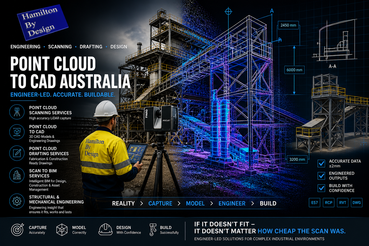
Hamilton By Design assists companies by capturing engineering-grade point cloud data using terrestrial 3D LiDAR scanning systems. Instead of relying on manual measurements or outdated PDFs, industrial facilities can be digitally captured with millimetre-level accuracy before engineering or fabrication work begins.
Unlike low-cost visual-only scanning services, Hamilton By Design operates as an engineer-led organisation focused on practical industrial and fabrication outcomes.
Using engineering-grade terrestrial LiDAR scanning equipment, facilities can be scanned to support:
- sawmill upgrades,
- conveyor redesigns,
- mechanical modifications,
- structural steel alterations,
- equipment replacements,
- dust extraction upgrades,
- and brownfield shutdown projects.
Captured point cloud data can then be converted into:
- 3D CAD models,
- as-built layouts,
- fabrication drawings,
- structural steel models,
- mechanical assemblies,
- engineering sections and elevations,
- and controlled documentation packages.
For timber mills and woodworking facilities, this provides a more reliable engineering foundation for maintenance planning, fabrication, construction, and operational upgrades.
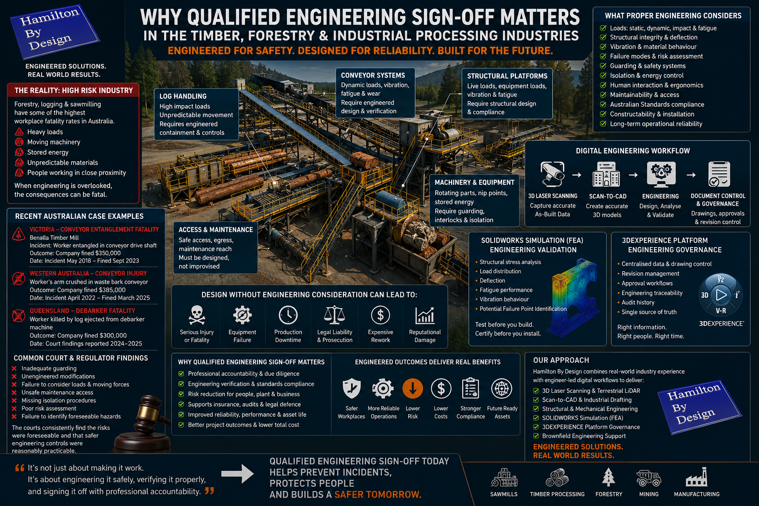
The woodworking and timber industries contain significant operational and mechanical risks. Equipment failures involving conveyors, saw systems, platforms, guarding, lifting systems, or structural supports can create serious safety consequences if engineering design, modifications, or fabrication are not properly managed.
Hamilton By Design supports companies through:
- accurate site measurement,
- engineering-grade scanning,
- structural and mechanical drafting,
- engineering modelling,
- and controlled engineering documentation systems.
Modern engineering workflows increasingly rely on:
- accurate as-built data,
- finite element analysis (FEA),
- controlled revision systems,
- and engineering governance platforms
to ensure modifications are properly documented and validated before installation.
Using technologies such as:
- terrestrial LiDAR scanning,
- SolidWorks 3D modelling,
- engineering simulation tools,
- and the 3DEXPERIENCE platform,
project teams can better understand loading conditions, structural interactions, fabrication requirements, and installation constraints before work proceeds onsite.
This helps reduce engineering uncertainty while improving safety, planning accuracy, and project coordination.
Hamilton By Design can also assist companies operating within brownfield industrial environments where construction and upgrades occur around existing operational equipment.
Brownfield facilities often present challenges including:
- restricted access,
- undocumented modifications,
- tight shutdown windows,
- difficult measurement conditions,
- and limited historical engineering information.
Through engineer-led scanning and digital engineering workflows, Hamilton By Design supports:
- shutdown planning,
- point cloud registration,
- scan-to-CAD conversion,
- equipment modelling,
- and engineering drawing development.
This allows engineers, fabricators, and project managers to work from accurate digital representations of the facility rather than assumptions or incomplete historical records.
For timber mills, woodworking facilities, and industrial plants in Prineville, this can significantly improve:
- fabrication accuracy,
- installation efficiency,
- shutdown coordination,
- and project delivery outcomes.
Hamilton By Design can support industrial facilities with:
- conveyor engineering,
- transfer chute layouts,
- structural steel drafting,
- equipment support structures,
- maintenance platforms,
- pipework drafting,
- access systems,
- and mechanical design support.
By integrating point cloud data directly into the engineering workflow, new infrastructure can be designed within the context of actual site conditions.
This is particularly valuable in older forestry and industrial facilities where:
- tolerances are tight,
- access is restricted,
- and existing drawings may no longer reflect reality.
As industrial facilities continue modernising, engineering governance and drawing control are becoming increasingly important. Many projects now require controlled revision systems, audit-ready documentation, and accurate digital engineering records.
Hamilton By Design supports structured engineering workflows through:
- controlled drawing revisions,
- digital engineering management,
- engineering document governance,
- and coordinated CAD environments.
This assists companies in maintaining:
- accurate as-built drawings,
- traceable engineering changes,
- controlled fabrication information,
- and long-term digital asset records.
For industrial facilities in Prineville, this supports safer operations, improved maintenance planning, and more efficient future expansion projects.
As Prineville continues growing across timber processing, forestry, manufacturing, industrial infrastructure, and technology sectors, the demand for accurate engineering information will continue increasing.
Hamilton By Design combines:
- engineering expertise,
- industrial plant knowledge,
- terrestrial LiDAR scanning,
- 3D CAD modelling,
- and engineering governance systems
to support safer and more efficient industrial project delivery.

Whether assisting with a timber mill upgrade, woodworking facility expansion, conveyor modification, shutdown project, structural steel redesign, or industrial mechanical installation, engineer-led 3D scanning provides a practical pathway toward improved engineering accuracy, reduced project risk, and more reliable long-term infrastructure management.