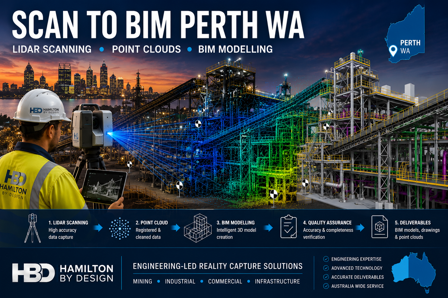
Scan to BIM Perth WA
Engineering-Led Scan to BIM Services Across Perth and Western Australia
Hamilton By Design provides professional Scan to BIM services throughout Perth and Western Australia, helping mining, industrial, commercial, infrastructure and construction organisations transform accurate 3D laser scan data into intelligent Building Information Models (BIM).
Using engineering-grade LiDAR scanning technology and advanced BIM workflows, we capture existing facilities, process plants, buildings and infrastructure assets and convert them into accurate digital models suitable for design, planning, construction and asset management.
Whether your project involves a brownfield mining upgrade in the Pilbara, a commercial building in the Perth CBD, a processing plant in Kwinana or infrastructure works across regional Western Australia, our Scan to BIM services deliver reliable information for better engineering and project outcomes.
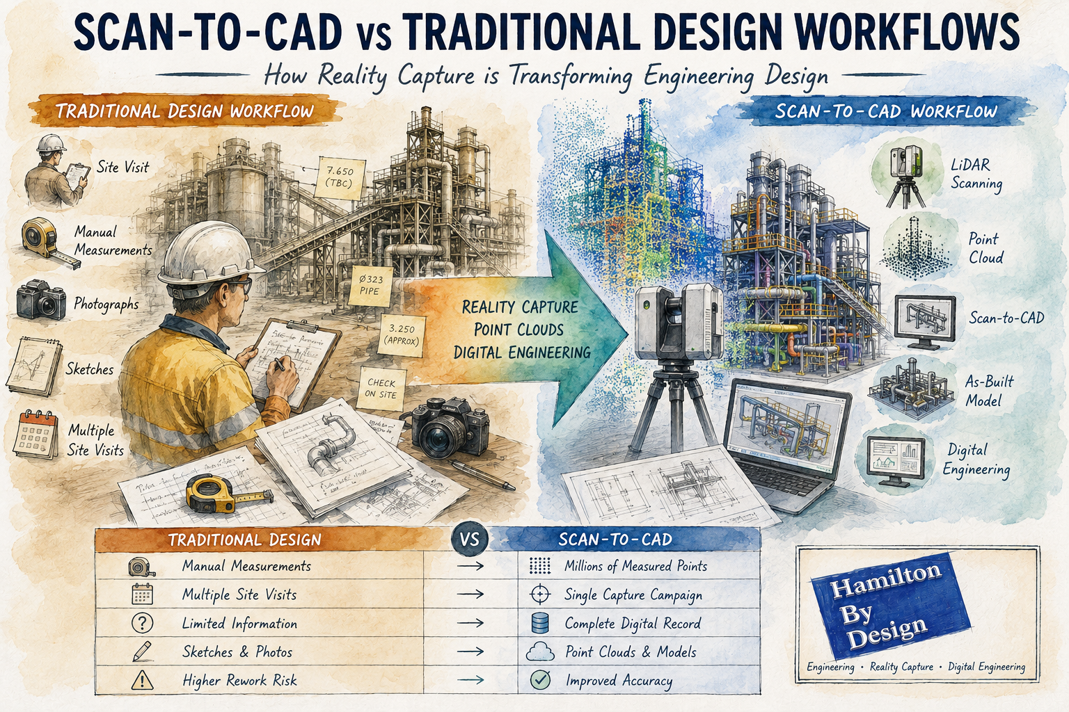
What is Scan to BIM?
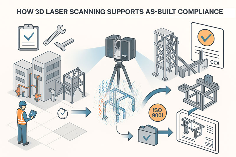
Scan to BIM is the process of converting 3D laser scan data into an intelligent Building Information Model.
The process begins with high-accuracy LiDAR scanning, which captures millions of measurement points across a site. This data forms a point cloud that accurately represents existing conditions.
The point cloud is then used to create a BIM model containing structural, architectural and mechanical information that can be used throughout the project lifecycle.
The result is a highly accurate digital representation of the asset that supports:
- Engineering design
- Construction planning
- Asset management
- Facility upgrades
- Maintenance planning
- Clash detection
- Digital twin development
Engineering-Led BIM Modelling
Unlike many scanning providers that focus only on data capture, Hamilton By Design combines engineering experience with reality capture technology.
This means the final BIM model is developed with an understanding of:
- Mechanical systems
- Structural steel
- Conveyors
- Chutes
- Tanks
- Pipework
- Platforms and access systems
- Process equipment
- Material handling infrastructure
Our engineering background allows us to understand how facilities operate and how accurate models can improve future design decisions.
Perth Industries Using Scan to BIM
Mining and Resources
Western Australia remains one of the world’s largest mining regions.
Scan to BIM supports:
- Iron ore facilities
- Gold processing plants
- Lithium operations
- Rare earth projects
- Bulk material handling systems
- Port infrastructure
Accurate BIM models help engineering teams reduce shutdown durations and improve planning for plant upgrades.
Industrial Manufacturing
Many Perth manufacturers operate facilities that have evolved over decades.
Often existing drawings are incomplete or outdated.
Scan to BIM enables:
- Accurate facility documentation
- Equipment replacement projects
- Structural upgrades
- Capacity expansion projects
- Maintenance planning
Commercial Buildings
Commercial property owners increasingly use BIM models to manage assets.
Applications include:
- Building refurbishment
- Services upgrades
- HVAC replacement
- Tenant fit-outs
- Facility management
Infrastructure Projects
Scan to BIM can support:
- Rail infrastructure
- Ports
- Water treatment facilities
- Pump stations
- Utility corridors
- Government infrastructure
Accurate BIM models reduce project risk by ensuring designs are based on real-world conditions.
Our Scan to BIM Workflow
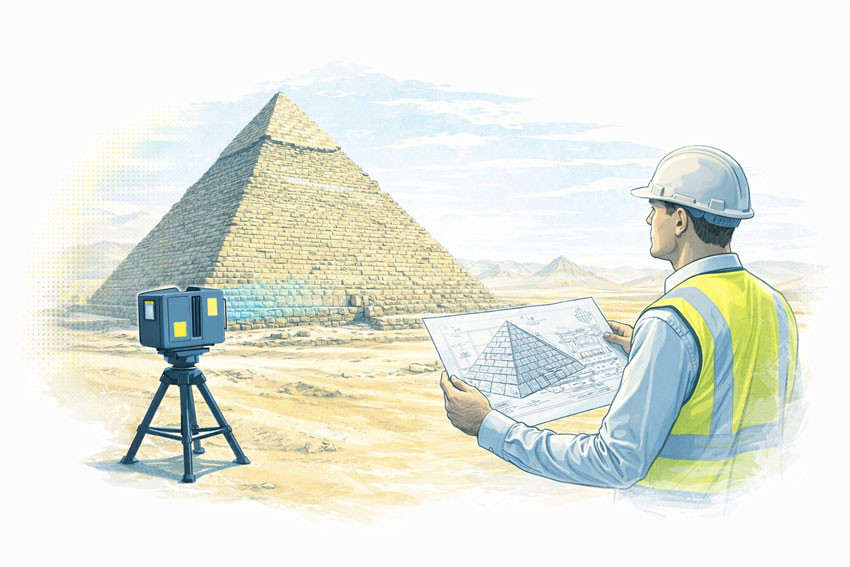
1. Site LiDAR Scanning
We perform engineering-grade laser scanning using professional reality capture equipment.
Millions of measurement points are collected across the facility.
2. Point Cloud Registration
Individual scans are aligned and processed into a unified point cloud.
Typical deliverables include:
- E57
- RCP
- RCS
- LAS
3. BIM Model Development
The point cloud is converted into BIM geometry using industry-standard software.
Models may include:
- Structural steel
- Mechanical equipment
- Pipework
- Buildings
- Platforms
- Access systems
4. Quality Assurance
Models are checked against scan data to verify accuracy and completeness.
5. Deliverables
Typical outputs include:
- Autodesk Revit Models
- Navisworks Models
- IFC Files
- DWG Drawings
- PDF Documentation
- Point Cloud Files
Benefits of Scan to BIM
Improved Accuracy
Laser scanning captures existing conditions with significantly greater accuracy than traditional site measurement methods.
Reduced Design Risk
Design teams can work from verified information rather than assumptions.
Faster Project Delivery
Accurate digital models reduce site revisits and minimise redesign.
Better Asset Management
Facility owners gain an accurate digital representation of their assets.
Improved Collaboration
BIM models provide a common source of information for engineers, designers, contractors and asset owners.
Scan to BIM for Brownfield Mining Projects
Brownfield projects often present unique challenges.
Existing facilities may contain undocumented modifications, ageing infrastructure and limited historical records.
Scan to BIM allows engineering teams to:
- Verify existing conditions
- Identify clashes before construction
- Reduce shutdown risks
- Improve design confidence
- Support future digital twin initiatives
For mining operations throughout Perth, the Pilbara, Goldfields and regional Western Australia, accurate BIM models can significantly improve project outcomes.
Why Choose Hamilton By Design?
Hamilton By Design combines:
✔ Engineering Experience
✔ LiDAR Scanning Expertise
✔ BIM Modelling Capability
✔ Mechanical Design Knowledge
✔ Structural Drafting Experience
✔ Australia-Wide Project Delivery
✔ Mining Industry Experience
We understand both the technology and the engineering requirements behind successful Scan to BIM projects.

Scan to BIM Perth WA
If you require Scan to BIM services in Perth or anywhere across Western Australia, Hamilton By Design can provide engineering-grade reality capture and BIM modelling solutions tailored to your project requirements.
From mining facilities and industrial plants to commercial buildings and infrastructure projects, we help organisations capture existing conditions and create accurate digital models that support safer, more efficient project delivery.
Talk to Us – Contact Us
Our clients: