3D Laser Scanning for Retail Fitouts | Hamilton By Design

3D Laser Scanning for Retail Fitouts
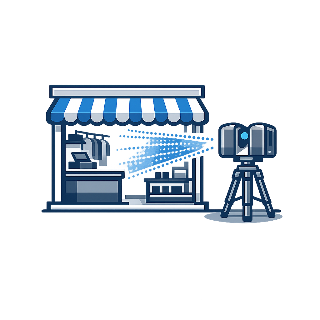
Icon of a retail shop fitout being scanned by a 3D laser scanner on a tripod, showing a storefront with awning, counter, shelving and clothing rack in a blue vector style.

Retail fitout projects often begin with incomplete drawings, outdated tenancy plans or commercial spaces that have been modified several times since their original construction. Even relatively small measurement errors can result in cabinetry that does not fit, services clashes, installation delays and expensive site rework.

Hamilton By Design provides engineer-led 3D laser scanning for retail fitouts, shop refurbishments and tenancy upgrades throughout Australia.

Using terrestrial LiDAR technology, we capture accurate existing-site conditions and convert the registered point-cloud data into practical Scan-to-CAD, as-built and three-dimensional modelling deliverables.

Our services support:

  • Retailers and property owners
  • Interior designers
  • Architects
  • Commercial builders
  • Shopfitters
  • Joinery manufacturers
  • Fitout contractors
  • Project managers
  • Building-services consultants
  • Shopping-centre tenancy coordinators

The objective is to provide dependable existing-condition information before detailed design, manufacturing or construction begins.

Accurate Existing-Condition Capture for Retail Spaces

Retail tenancies are rarely as simple as the original drawings suggest. Walls may be out of square, floors may vary in level, columns may differ from the tenancy plan and existing building services may conflict with the proposed design.

Through engineering-grade 3D laser scanning across Australia, Hamilton By Design can record millions of measured points throughout a shop, tenancy or commercial building.

These measurements form a detailed three-dimensional point cloud representing the visible geometry of the existing environment.

Depending on the agreed scope, scanning can capture:

  • Internal walls and partitions
  • Shopfronts and entry openings
  • Floors, ceilings and bulkheads
  • Columns, beams and structural elements
  • Existing counters and display fixtures
  • Mechanical ductwork and air-conditioning outlets
  • Fire services and sprinkler locations
  • Electrical boards, lighting and cable trays
  • Plumbing fixtures and visible pipework
  • Stairs, ramps and changes in floor level
  • Loading areas and back-of-house spaces
  • Access routes for equipment and installation

The resulting point cloud provides designers and contractors with a reliable digital foundation for the proposed retail fitout.

Reduce Site Rework and Installation Problems

Traditional measurement methods may be suitable for simple rooms, but retail fitouts frequently contain complex geometry, restricted access, congested ceiling services and tightly coordinated architectural finishes.

A manual survey may record selected dimensions without capturing the complete spatial relationship between walls, floors, ceilings, services, shopfronts and structural elements.

Important information can be overlooked, resulting in:

  • Additional site visits
  • Incorrect shop drawings
  • Joinery modifications
  • Delayed installation
  • Services relocation
  • Unplanned building work
  • Programme disruption
  • Increased project costs

A comprehensive laser scan creates a reusable digital record of the tenancy.

The point-cloud data can help the project team:

  • Verify tenancy dimensions before design begins
  • Check whether walls are straight, square and plumb
  • Confirm floor levels and ceiling heights
  • Identify visible building services
  • Coordinate joinery, signage and display systems
  • Review access and installation clearances
  • Detect potential clashes before construction
  • Reduce repeated site-measurement visits
  • Support off-site fabrication
  • Document existing conditions before demolition

This improves design confidence and reduces the likelihood of discovering dimensional problems during installation.

Scan-to-CAD for Retail Fitout Design

Hamilton By Design can convert registered scan data into practical CAD information for use by designers, architects, shopfitters and fabrication contractors.

Our broader engineering and digital design services include point-cloud processing, CAD modelling, drafting, reverse engineering and as-built documentation.

Retail Scan-to-CAD deliverables may include:

  • Existing-condition floor plans
  • Reflected ceiling plans
  • Internal elevations
  • Shopfront elevations
  • Building sections
  • Wall and column locations
  • Floor-level plans
  • Ceiling and bulkhead geometry
  • Visible-services layouts
  • Three-dimensional CAD models
  • Dimensional verification drawings
  • As-built documentation

For projects requiring more detailed digital geometry, our 3D point-cloud modelling services can transform selected point-cloud information into structured CAD models suitable for design coordination and fabrication planning.

Deliverables can be developed to suit the required level of detail and intended downstream use.

Common delivery formats include:

  • DWG
  • DXF
  • PDF
  • STEP
  • SAT
  • Parasolid
  • E57
  • RCP
  • RCS
  • LAS

The registered point cloud may also be supplied directly to the clientโ€™s design team for use in AutoCAD, Revit, Navisworks, SolidWorks, Autodesk ReCap or other compatible software.

Retail Fitout Applications

Hamilton By Design can support a wide range of retail refurbishment, tenancy and commercial fitout projects.

New Retail Fitouts

Before a new tenancy is fitted out, laser scanning can confirm the actual dimensions and condition of the available space.

This provides the design team with accurate information for planning:

  • Internal walls
  • Counters
  • Shelving
  • Product displays
  • Storage areas
  • Signage
  • Lighting
  • Services
  • Customer circulation
  • Accessible routes

Designing from the scan reduces reliance on leasing drawings or older plans that may not accurately represent the current tenancy.

Shop Refurbishments

Existing stores often contain fixtures, structures and services that must remain operational or be incorporated into the new design.

Scanning provides a detailed record of the current shop layout before refurbishment work begins. This can assist with staged works, selective demolition and coordination around retained elements.

Tenancy Upgrades

Tenancy upgrades may involve changes to ceilings, lighting, air conditioning, services, shopfronts, access arrangements or internal layouts.

A registered point cloud helps coordinate the proposed work with the existing building geometry.

Multi-Site Retail Rollouts

Retailers completing similar fitouts across multiple locations can use laser scanning to capture each tenancy through a consistent measurement process.

This can help identify site-specific variations before standard joinery, signage, fixtures and finishes are manufactured.

Shopping-Centre Tenancies

Shopping-centre fitouts must often coordinate with:

  • Base-building structures
  • Common building services
  • Fire-protection systems
  • Centre-management requirements
  • Mall interface levels
  • Loading and access arrangements
  • Restricted working hours

Laser scanning can document the tenancy and its connection to surrounding spaces while helping minimise disruption to adjacent retail operations.

Supermarkets and Large Retail Stores

Supermarkets and larger retail environments may include complex ceiling services, refrigeration equipment, storage areas, loading zones and operational constraints.

Laser scanning can capture substantial areas efficiently and provide information for equipment upgrades, refurbishments, new departments and revised store layouts.

Hospitality and Food Retail

Cafรฉs, restaurants, takeaway outlets and commercial kitchens require careful coordination between equipment, exhaust systems, plumbing, electrical services and existing building geometry.

Retail food projects may benefit from the same accurate existing-condition approach used for 3D laser scanning in hospitality environments.

The scan can assist designers with equipment layouts, exhaust-routing studies, service connections, stainless-steel fabrication and installation clearances.

Retail De-Fits and Make-Good Works

Scanning can document the condition of a tenancy before strip-out, de-fit or make-good works begin.

The dataset may assist with:

  • Demolition planning
  • Scope development
  • Existing-condition records
  • Retained-services identification
  • Base-building reinstatement
  • Contractor coordination
  • Tenancy handover documentation

Support for Joinery and Shopfitting Contractors

Custom retail joinery is frequently manufactured off site before being delivered during a narrow construction or installation window.

Incorrect site dimensions can result in costly workshop alterations or site modifications.

Laser scanning can provide accurate information for:

  • Service counters
  • Reception counters
  • Display cabinets
  • Wall-mounted shelving
  • Feature walls
  • Banquette seating
  • Storage cabinets
  • Retail kiosks
  • Product displays
  • Signage structures
  • Ceiling-mounted features
  • Custom architectural elements

Hamilton By Design can also develop selected existing geometry through its reverse-engineering and 3D scanning services.

This may include modelling surrounding walls, floors, columns, shopfronts or structural interfaces that affect the fit and installation of a custom component.

Shopfront and Faรงade Measurement

Retail shopfronts often require detailed measurement for:

  • Glazing
  • Framing
  • Signage
  • Entry doors
  • Security shutters
  • Architectural finishes
  • Structural connections
  • Mall interfaces

Three-dimensional laser scanning can capture the existing shopfront and surrounding building geometry without relying solely on individual tape or laser-distance measurements.

The captured information may be used to produce:

  • Shopfront elevations
  • Opening dimensions
  • Glazing geometry
  • Structural interface details
  • Signage locations
  • Floor and ceiling relationships
  • Adjacent wall conditions
  • Door and access clearances

This can be especially valuable when replacement shopfront elements must be designed or manufactured before the existing installation is removed.

Ceiling and Building-Services Coordination

The ceiling space is one of the most congested areas in many retail fitouts.

Proposed lighting, signage, bulkheads and architectural features may need to coordinate with existing:

  • Air-conditioning ductwork
  • Supply-air diffusers
  • Return-air grilles
  • Sprinkler heads
  • Fire detectors
  • Emergency lighting
  • Security cameras
  • Speakers
  • Electrical services
  • Ceiling access panels

Laser scanning can record visible ceiling geometry and service locations to support a coordinated reflected ceiling plan.

This information can help identify conflicts involving:

  • New lighting layouts
  • Suspended signage
  • Decorative ceiling features
  • Joinery extending to the ceiling
  • Mechanical-services modifications
  • Fire-services coordination
  • New partitions
  • Access requirements

Laser scanning records visible surfaces and does not replace specialist investigations where concealed services must be located behind walls, ceilings or floors.

Floor Levels and Surface Variations

Retail flooring, cabinetry and shopfront installations may be affected by uneven slabs, ramps, thresholds and changes in floor level.

Laser scanning can provide level information across visible areas of the tenancy and help identify:

  • Sloping floors
  • Localised high and low points
  • Changes between floor finishes
  • Entry thresholds
  • Ramps and steps
  • Existing plinths
  • Raised display areas
  • Interfaces with common mall areas
  • Levels at door openings
  • Potential installation packing requirements

This information can support flooring design, accessibility planning, cabinetry installation and coordination with adjoining spaces.

Point-Cloud and As-Built Deliverables

Following site capture, individual scanning positions are registered together to create a coordinated three-dimensional point cloud.

Depending on the agreed project scope, Hamilton By Design can provide:

  • Registered colourised point clouds
  • E57 point-cloud files
  • Autodesk ReCap RCP or RCS files
  • LAS files
  • Panoramic scan imagery
  • Cropped point clouds for defined work areas
  • CAD drawings developed from the scan
  • Simplified three-dimensional existing-condition models
  • Shopfront elevations
  • Dimensional verification drawings
  • As-built drawing packages

Our engineering services also support projects where legacy drawings are missing, incomplete or no longer reflect the installed condition.

The appropriate deliverables will depend on the tenancy size, proposed design workflow, software platform and level of information required by the project team.

Engineer-Led Retail Fitout Scanning

Hamilton By Design combines laser scanning with practical mechanical engineering, CAD, drafting, fabrication and construction experience.

This engineer-led approach helps identify the information that is likely to matter during design, manufacture and installation.

The objective is not simply to produce a visually impressive point cloud. It is to provide useful existing-condition information that supports project decisions.

This approach is particularly valuable when the retail fitout includes:

  • Custom-fabricated components
  • Mechanical equipment
  • Structural supports
  • Suspended architectural features
  • Access platforms or stairs
  • Commercial kitchen equipment
  • Exhaust and ventilation systems
  • Complex service coordination
  • Restricted installation clearances
  • Equipment replacement or modification

Projects requiring broader mechanical input can also be supported through Hamilton By Designโ€™s mechanical engineering and design services.

Typical Retail Fitout Scanning Process

1. Scope Review

We review the tenancy location, project objectives, required areas, expected accuracy, access conditions and intended deliverables.

Useful information at this stage includes:

  • Site address
  • Approximate tenancy area
  • Available plans
  • Required scan coverage
  • Intended CAD or point-cloud format
  • Access hours
  • Centre-management requirements
  • Proposed construction programme

2. Site Planning

Scan positions are planned to capture the required geometry while working around fixtures, stock, staff, customers and other site restrictions.

For operational shops, scanning may be scheduled before opening, after closing or during a dedicated access period.

3. On-Site Laser Scanning

The tenancy is scanned from multiple positions to capture walls, floors, ceilings, shopfronts, structural elements and visible services.

Overlapping scan positions allow the separate datasets to be registered together.

4. Point-Cloud Registration

The individual scans are processed and aligned into a coordinated three-dimensional dataset.

5. Quality Review

The registered point cloud is reviewed for alignment, coverage and suitability for the agreed deliverables.

6. CAD and Drawing Production

Where requested, the point cloud is interpreted and converted into floor plans, elevations, sections or selected three-dimensional CAD models.

7. Project Delivery

The agreed point-cloud, CAD, drawing and image files are supplied to the client or nominated design consultant.

Scanning Operational Retail Environments

Retail projects often require scanning to be completed while the store, shopping centre or surrounding premises remain operational.

Hamilton By Design can plan scanning around:

  • Restricted trading hours
  • Early-morning access
  • Night works
  • Weekend access
  • Customer exclusion zones
  • Centre-management procedures
  • Loading-dock bookings
  • Security requirements
  • Contractor inductions
  • Short tenancy-access windows

A terrestrial scanner captures measurements remotely and can record substantial areas without physically measuring every individual surface.

Temporary obstructions, stock, displays and moving people can affect visibility. A clear, clean and well-prepared work area generally produces the most complete dataset.

Retail Fitout Projects We Can Support

Hamilton By Design can provide laser scanning for:

  • Clothing stores
  • Supermarkets
  • Shopping-centre tenancies
  • Department stores
  • Pharmacies
  • Medical retail tenancies
  • Jewellery stores
  • Furniture showrooms
  • Automotive showrooms
  • Cafรฉs and restaurants
  • Food-court tenancies
  • Commercial kitchens
  • Banks and financial-service branches
  • Gyms and fitness centres
  • Hair and beauty salons
  • Bottle shops
  • Convenience stores
  • Pop-up stores
  • Retail kiosks
  • Warehouse retail outlets
  • Office and showroom refurbishments

Why Use 3D Laser Scanning for a Retail Fitout?

The principal benefits include:

  • Accurate capture of existing conditions
  • Reduced reliance on outdated tenancy drawings
  • Fewer manual measurement errors
  • Improved coordination between project consultants
  • Reduced risk of fabrication errors
  • Fewer return site visits
  • Better planning before demolition
  • Improved off-site manufacturing confidence
  • Detailed documentation of complex spaces
  • Support for clash detection
  • A reusable digital record of the tenancy

For fast-moving retail fitout projects, dependable site information can help protect the construction programme and reduce costly rework.

3D Laser Scanning for Retail Fitouts Across Australia

Hamilton By Design provides retail and commercial scanning services across Australia.

Our established location services include:

We can also support projects in Newcastle, Canberra, Adelaide, Darwin, regional centres and remote Australian locations.

Travel, inductions, restricted access and after-hours scanning requirements can be incorporated into the project scope.

Frequently Asked Questions

How accurate is 3D laser scanning for retail fitouts?

The achievable result depends on the scanner, scanning distance, surface conditions, registration method, site access and required deliverables.

Terrestrial laser scanning can provide detailed, millimetre-level spatial data suitable for existing-condition capture, fitout coordination and as-built documentation.

Project-specific accuracy requirements should be discussed before scanning begins.

Can you scan a shop while it is still trading?

Scanning may be possible in an operating retail environment. However, customers, stock, displays and moving staff can obstruct important surfaces.

Early-morning, night or weekend access may provide a clearer and more complete dataset.

Can the scan be converted into AutoCAD drawings?

Yes. Registered point-cloud data can be used to prepare:

  • DWG floor plans
  • Reflected ceiling plans
  • Elevations
  • Sections
  • Shopfront drawings
  • Selected services drawings
  • Existing-condition layouts

Can you create a three-dimensional CAD model?

Yes. Selected geometry can be converted into structured CAD models.

The required model content and level of detail should be defined before work begins. Further information is available through our point-cloud modelling and reverse-engineering services.

Can the point cloud be used in Revit?

Point clouds can be supplied in formats suitable for import or linking within Revit and other Autodesk platforms.

Project-specific Scan-to-BIM requirements should be agreed separately, including model elements, level of detail and required outputs.

Can you measure floor levels?

Yes. Laser scanning can record visible floor geometry and level variations throughout the tenancy.

Can scanning locate concealed services?

Laser scanning records visible surfaces. It generally cannot see through walls, floors or ceilings.

Concealed services may require specialist service locating, non-destructive investigation, existing documentation or selective access.

Can you scan only one section of a store?

Yes. The scanning scope can be limited to a specific:

  • Shopfront
  • Ceiling area
  • Joinery interface
  • Equipment zone
  • Commercial kitchen
  • Loading area
  • Back-of-house room
  • Services corridor
  • Installation interface

What information is required for a quotation?

Helpful information includes:

  • Site location
  • Approximate tenancy size
  • Required areas
  • Available drawings or photographs
  • Intended deliverables
  • Access conditions
  • Proposed scanning date
  • Required turnaround
  • Site inductions
  • Restricted working hours

Request a Retail Fitout Scanning Quotation

Hamilton By Design provides 3D laser scanning for retail fitouts, shop refurbishments and tenancy upgrades, supported by practical engineering, CAD and fabrication experience.

Whether your project requires a registered point cloud, existing-condition floor plan, reflected ceiling plan, shopfront elevation or Scan-to-CAD model, the scope can be tailored to suit your design and construction requirements.

Contact Hamilton By Design to discuss your retail tenancy, site-access requirements, required deliverables and proposed project programme.

For more information, visit our main 3D laser scanning services page or review our engineering services.


Hamilton By Design logo displayed on a blue tilted rectangle with a grey gradient background

Contact Us – Talk To Us

Name
Would you like us to arrange a phone consultation for you?
Address

Our clients:


https://www.hamiltonbydesign.com.au/scan-to-bim-services-australia-lidar-point-clouds-cad-modelling

Scan to CAD Port of Brisbane | 3D LiDAR Scanning

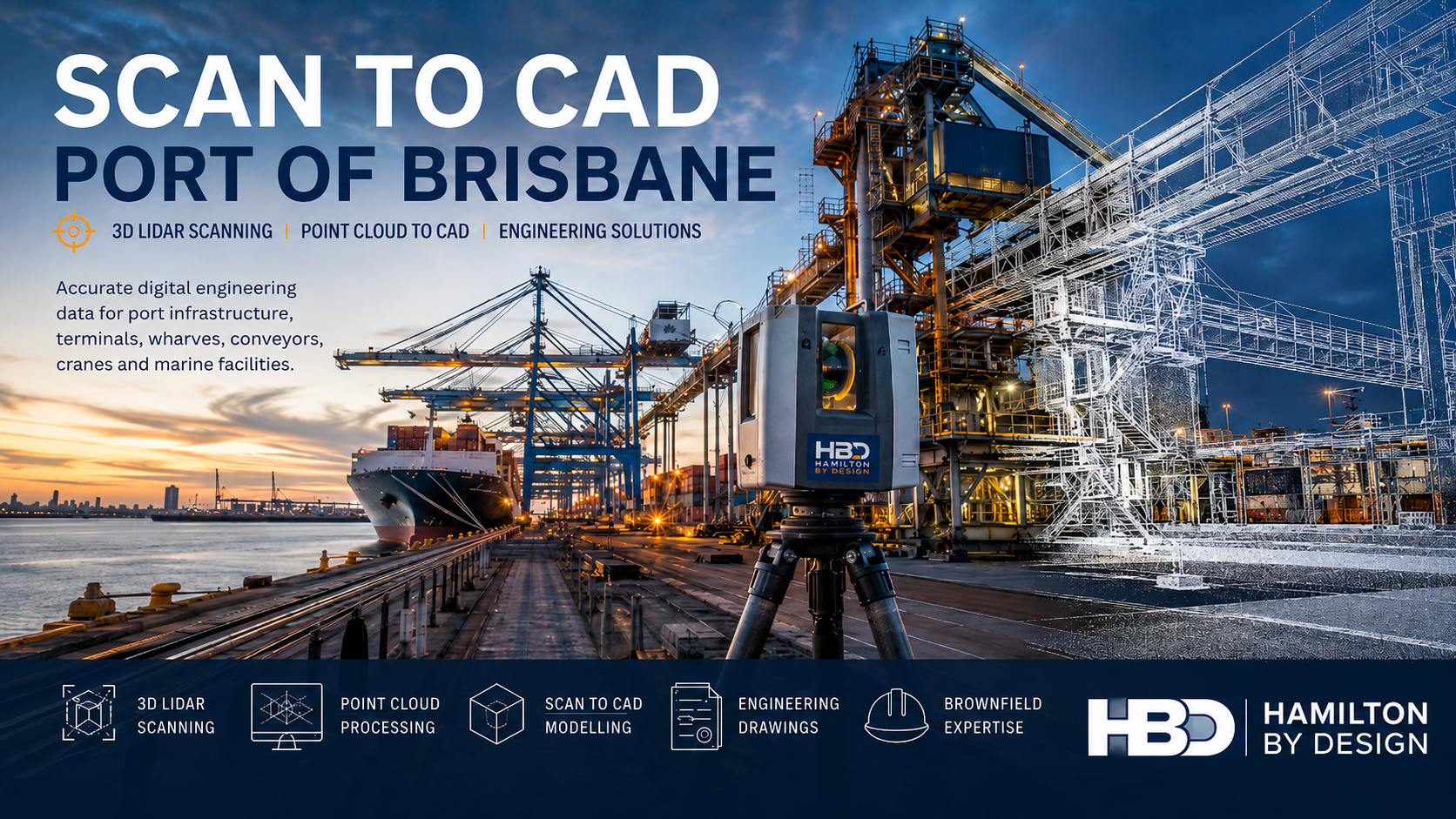
Scan to CAD at the Port of Brisbane showing a 3D LiDAR scanner, container ship, port cranes and point-cloud CAD model of industrial infrastructure.

Scan to CAD Port of Brisbane

Engineering-Grade 3D LiDAR Scanning and CAD Modelling for Port Facilities

Blue 3D LiDAR scanner icon on a tripod with scanning waves

Port facilities are complex industrial environments containing wharves, container terminals, conveyors, ship-loading equipment, cranes, structural steel, pipework, access systems and marine infrastructure.

Over time, port equipment may be repaired, reinforced, relocated, replaced or modified without every change being accurately reflected in the original drawings.

Hamilton By Design provides Scan to CAD services for the Port of Brisbane, converting engineering-grade LiDAR point-cloud data into practical CAD models, drawings and digital engineering information.

Our engineer-led workflow combines LiDAR scanning in Brisbane with point cloud to CAD modelling, mechanical engineering and fabrication-focused drafting.

This enables project teams to design around the actual port facility rather than relying on incomplete drawings, isolated site measurements or assumptions.


What Is Scan to CAD?

Scan to CAD is the process of capturing an existing asset or facility with 3D laser scanning and converting the resulting point cloud into structured CAD geometry.

A typical workflow includes:

Project planning โ†’ Site scanning โ†’ Point-cloud registration โ†’ CAD modelling โ†’ Engineering drawings

The completed models and drawings may be prepared for use in:

  • AutoCAD
  • SolidWorks
  • Autodesk Inventor
  • Navisworks
  • Revit
  • Plant-design software
  • Structural-drafting systems
  • Fabrication and construction documentation

Hamilton By Design provides more than a visual point cloud. Our engineering-led 3D scanning services in Brisbane are structured around the projectโ€™s intended engineering, fabrication, maintenance or construction outcome.


Scan to CAD for the Port of Brisbane

The Port of Brisbane is a major Queensland trade and logistics hub supporting containerised cargo, bulk products, motor vehicles, general cargo and other maritime activities.

Its facilities include container berths, bulk-handling terminals, common-user facilities and the Brisbane Multimodal Terminal, which provides an interface between rail, road and container-terminal operations.

Infrastructure in and around the port may include:

  • Container-handling equipment
  • Ship-to-shore cranes
  • Automated stacking-crane infrastructure
  • Conveyors and transfer stations
  • Ship loaders and unloaders
  • Hoppers and chutes
  • Wharf structures
  • Marine loading equipment
  • Fuel and chemical infrastructure
  • Rail and road interfaces
  • Maintenance workshops
  • Structural-steel platforms
  • Stairs, ladders and handrails
  • Pipe racks and process pipework

The Port of Brisbaneโ€™s container facilities include multiple container berths operated by major stevedores using automated container-handling equipment.

Scan to CAD provides an accurate digital baseline before modification, maintenance or upgrade work begins.


Why Port Facilities Benefit from Scan to CAD

Traditional site measurement usually requires designers to identify every required dimension before attending site.

When another measurement is needed later, another site visit may be required.

This can be difficult within an operating port environment where access may involve:

  • Port or terminal inductions
  • Maritime-security controls
  • Work permits
  • Escort requirements
  • Traffic-management arrangements
  • Crane and mobile-equipment movements
  • Restricted wharf access
  • Work near water
  • Vessel movements
  • Limited shutdown windows
  • Coordination with operations personnel

A coordinated 3D point-cloud scan captures millions of measured points throughout the work area.

Once registered, the point cloud allows engineers and designers to revisit the digital site and review:

  • Dimensions
  • Elevations
  • Clearances
  • Structural interfaces
  • Pipework locations
  • Equipment positions
  • Access constraints
  • Installation routes
  • Surrounding obstructions

This can reduce repeated site attendance while providing a more complete understanding of the existing environment.


Scan Existing Port Infrastructure Once and Use It Repeatedly

A well-planned scan can become a reusable digital reference for engineering, drafting, fabrication and maintenance teams.

The point cloud may be used to support:

  • Concept development
  • Detailed design
  • Equipment replacement
  • Structural modifications
  • Fabrication drawings
  • Clash detection
  • Installation planning
  • Shutdown planning
  • As-built documentation
  • Maintenance-access reviews
  • Future upgrade projects

Hamilton By Designโ€™s reality capture services in Brisbane integrate site capture with Scan to CAD, as-built documentation and engineering design.

This means the scan is planned around what the project team needs to achieve, rather than simply collecting large quantities of unstructured data.


Port Equipment and Infrastructure We Can Capture

Wharves and Marine Structures

LiDAR scanning can capture the accessible and visible geometry of:

  • Wharf decks
  • Structural framing
  • Fender-support structures
  • Bollards
  • Mooring equipment
  • Access ladders
  • Handrails
  • Service trenches
  • Crane rails
  • Wharf-mounted equipment
  • Pipework and services
  • Equipment foundations

The resulting CAD model can support maintenance planning, structural modifications, equipment installation and existing-condition documentation.

For projects involving broader building or infrastructure information, Hamilton By Design can also provide Scan to BIM services in Brisbane.


Container-Terminal Infrastructure

Container terminals contain complex interfaces between cranes, automated equipment, road vehicles, rail infrastructure, barriers, services and maintenance areas.

Scan to CAD can assist with projects involving:

  • Ship-to-shore crane interfaces
  • Automated stacking-crane areas
  • Container-transfer equipment
  • Crane rails
  • Maintenance access
  • Safety barriers
  • Equipment foundations
  • Cable routes
  • Traffic interfaces
  • Structural modifications
  • Services and utilities

The point cloud allows proposed equipment and structures to be reviewed within the measured terminal environment before fabrication or installation.


Conveyors, Chutes and Bulk-Materials Equipment

Bulk-handling equipment is often congested, elevated and difficult to measure manually.

Hamilton By Design can scan:

  • Belt conveyors
  • Transfer stations
  • Chutes
  • Hoppers
  • Bins
  • Feeders
  • Ship loaders
  • Ship unloaders
  • Scrapers
  • Support structures
  • Walkways
  • Maintenance platforms
  • Dust-extraction systems

Our chute design and materials-handling services can combine accurate existing-condition data with CAD modelling and engineering design.

This can support chute replacement, conveyor modification, wear assessment and materials-handling upgrades.


Ship Loaders and Port-Loading Equipment

Ship loaders contain large structural, mechanical and materials-handling systems that can be difficult to document with conventional measurement methods.

Scan to CAD can support:

  • Structural-steel modifications
  • Conveyor replacement
  • Chute upgrades
  • Access-platform design
  • Mechanical-equipment replacement
  • Slew and travel interfaces
  • Maintenance-access studies
  • Pipework and service modifications
  • As-built documentation
  • Installation and shutdown planning

Hamilton By Designโ€™s experience with ship-loader 3D scanning demonstrates how engineering-grade point clouds can support Scan to CAD, port infrastructure modifications and brownfield design.


Mechanical Equipment and Pipework

Scan to CAD can also document:

  • Pumps
  • Valves
  • Pipework
  • Ducting
  • Tanks
  • Mechanical skids
  • Loading systems
  • Hydraulic equipment
  • Equipment supports
  • Service platforms
  • Maintenance-access systems
  • Replacement components

Where existing components must be reproduced or redesigned, the scan can form part of a structured reverse-engineering process.


Rail and Road Interfaces

Port operations depend on coordinated movement between marine, road and rail systems.

LiDAR scanning can capture:

  • Rail alignments
  • Road interfaces
  • Loading areas
  • Transfer zones
  • Traffic barriers
  • Equipment clearances
  • Structures
  • Services
  • Signage supports
  • Access routes
  • Vehicle envelopes

The Brisbane Multimodal Terminal provides a designated interface between rail, road and the Port of Brisbane container terminals.

A coordinated point cloud can help project teams assess how proposed modifications interact with these operating areas.


Scan to CAD for Brownfield Port Upgrades

Most port modification projects are brownfield projects.

New equipment must fit around existing structures, pipework, electrical services, access platforms and operating systems.

Even a relatively small dimensional discrepancy can result in:

  • Fabrication rework
  • Installation delays
  • Site cutting and welding
  • Crane delays
  • Extended shutdowns
  • Access problems
  • Service clashes
  • Additional engineering work
  • Increased safety exposure
  • Higher project costs

Hamilton By Designโ€™s Scan to CAD workflow allows proposed equipment to be developed within the measured site environment.

This helps the project team understand:

  • What is actually installed
  • Where surrounding structures are located
  • Whether sufficient access is available
  • How the equipment may be installed
  • Whether fabricated components can reach their final position
  • Where clashes may occur
  • Which existing assets may require modification

Supporting Port Modification Projects

Scan to CAD can support a wide range of port projects, including:

  • Conveyor replacements
  • Transfer-chute upgrades
  • New maintenance platforms
  • Crane-access modifications
  • Equipment relocations
  • Pipework upgrades
  • Dust-extraction improvements
  • Ship-loader modifications
  • Wharf-service upgrades
  • Structural-steel additions
  • Machine guarding
  • Safety-access improvements
  • Demolition planning
  • Shutdown projects
  • As-built documentation

Hamilton By Design can combine Scan to CAD with broader engineering services, including mechanical design, structural drafting, 3D modelling and fabrication documentation.


Our Port of Brisbane Scan to CAD Workflow

1. Project Scope and Scan Planning

Before attending site, we establish:

  • The project objective
  • The required scan area
  • The required CAD deliverables
  • Critical equipment interfaces
  • Required level of detail
  • Accuracy expectations
  • Site-access conditions
  • Operational restrictions
  • Safety requirements
  • Coordinate-system requirements
  • File-format requirements

Planning the scan around the intended deliverable helps ensure that the required geometry is captured.


2. Site Access and Safety Planning

Port work can involve moving machinery, suspended loads, heavy vehicles, vessel operations, operating conveyors and water-edge hazards.

The scanning methodology may need to consider:

  • Port and terminal inductions
  • Safe Work Method Statements
  • Take 5 risk assessments
  • Exclusion zones
  • Traffic movements
  • Crane operations
  • Work near water
  • Restricted areas
  • Communication requirements
  • Shutdowns and isolations

Scanning positions are selected to capture the required information while minimising interference with port operations.


3. Engineering-Grade LiDAR Capture

Hamilton By Design uses professional terrestrial LiDAR equipment to capture detailed site geometry.

Multiple scan positions are typically established around the work area to reduce shadows and improve coverage around:

  • Structural members
  • Pipework
  • Mechanical equipment
  • Conveyor systems
  • Platforms
  • Services
  • Access routes
  • Equipment interfaces

Further information about our national scanning capability is available through our engineering-grade 3D laser scanning service.


4. Point-Cloud Registration

Individual scans are aligned into a coordinated point-cloud dataset.

The registered point cloud is reviewed for:

  • Alignment quality
  • Site coverage
  • Noise and unwanted data
  • Missing areas
  • Critical interfaces
  • Dimensional consistency
  • Coordinate control

The registered dataset may then be supplied directly or used as the basis for CAD modelling and engineering documentation.


5. CAD Modelling

Required geometry is extracted from the point cloud and converted into fit-for-purpose CAD information.

Depending on the project, this may include:

  • Simplified spatial models
  • Mechanical-equipment models
  • Structural-steel models
  • Pipework models
  • Conveyor models
  • Equipment envelopes
  • Platforms and access systems
  • Existing-condition drawings
  • Fabrication-ready models

Not every visible object needs to be modelled.

The required level of detail should be established according to the engineering purpose of the project.


6. Engineering and Constructability Review

Where required, the scan-derived CAD model can support:

  • Mechanical design
  • Structural-arrangement development
  • Clash detection
  • Access reviews
  • Installation planning
  • Equipment fit checks
  • Maintenance-access studies
  • Fabrication documentation
  • Engineering verification

Hamilton By Designโ€™s SolidWorks services in Brisbane can be used to develop mechanical models, assemblies and drawings from the measured site data.


7. Project Deliverables

Available project deliverables may include:

  • Registered point clouds
  • E57 files
  • RCP files
  • RCS files
  • LAS files
  • AutoCAD DWG drawings
  • DXF files
  • SolidWorks models
  • Autodesk Inventor models
  • STEP files
  • SAT files
  • Parasolid files
  • Navisworks coordination models
  • General-arrangement drawings
  • Plans, sections and elevations
  • Fabrication drawings
  • Existing-condition reports

The final deliverables are agreed during project scoping so the capture, processing and modelling effort remains aligned with the intended use.


Engineer-Led Scan to CAD

The value of a Scan to CAD project depends on more than the scanner being used.

The person planning the capture needs to understand what engineers, designers and fabricators will require from the data.

Hamilton By Design combines:

  • Mechanical-engineering experience
  • Industrial LiDAR scanning
  • Point-cloud registration
  • SolidWorks modelling
  • AutoCAD drafting
  • Structural and mechanical drafting
  • Fabrication knowledge
  • Brownfield-design experience
  • Practical site experience

Our 3D scanning engineering service in Brisbane combines site capture with CAD modelling, mechanical design and fabrication-ready drafting.

This integrated approach helps ensure important interfaces are captured and the final model is appropriate for its intended engineering purpose.


Designing Around Real Port Conditions

Port equipment may have been:

  • Repaired
  • Reinforced
  • Replaced
  • Relocated
  • Modified
  • Distorted
  • Worn
  • Supplemented with additional steelwork
  • Changed without drawing updates

An original drawing should therefore not automatically be treated as a reliable as-built record.

Scan to CAD allows designers to compare physical site conditions against available drawings and establish a more dependable basis for new work.

This is particularly valuable when designing:

  • Replacement components
  • New platforms
  • Conveyor modifications
  • Pipe supports
  • Equipment foundations
  • Structural frames
  • Guards and barriers
  • Maintenance-access systems
  • Retrofit steelwork

Clash Detection Before Fabrication

A scan-derived model can be combined with the proposed design to identify potential clashes before materials are ordered or components are fabricated.

Possible clashes may involve:

  • Existing structural steel
  • Pipework
  • Cable trays
  • Handrails
  • Mechanical equipment
  • Conveyor components
  • Access routes
  • Crane operating envelopes
  • Maintenance-removal paths
  • Vehicle clearances

Identifying these issues during the CAD stage is generally safer and less disruptive than discovering them during installation or a restricted port shutdown.


Installation and Shutdown Planning

Port shutdowns and installation windows may be tightly controlled.

Scan to CAD can assist project teams in reviewing:

  • Component sizes
  • Lift requirements
  • Crane positions
  • Installation sequences
  • Temporary access
  • Removal paths
  • Laydown areas
  • Existing obstructions
  • Required demolition
  • Temporary-support requirements

A coordinated point cloud also allows contractors, fabricators and project stakeholders to review the site remotely before mobilisation.


As-Built Verification

Following installation, selected areas may be rescanned and compared with the design model.

This can help verify:

  • Equipment position
  • Structural alignment
  • Pipe routing
  • Clearances
  • Installed geometry
  • Construction tolerances
  • Differences between design and installation

The resulting model can provide a dependable digital record for future maintenance, modification and asset-management activities.


Scan to CAD Compared with Manual Measurement

Manual measurement remains suitable for simple and accessible assets.

However, conventional measurement becomes more difficult where a project contains:

  • Complex geometry
  • Congested equipment
  • Elevated structures
  • Multiple operating levels
  • Restricted access
  • Large work areas
  • Irregular surfaces
  • Numerous equipment interfaces
  • Limited time on site

LiDAR scanning captures the spatial relationship between assets instead of producing a disconnected collection of individual measurements.

Critical dimensions may still be independently verified where required, but the point cloud provides the broader engineering context.


Benefits for Port Owners and Operators

Scan to CAD can provide:

  • Better existing-condition information
  • Reduced reliance on outdated drawings
  • Fewer repeated site visits
  • Improved design coordination
  • Earlier clash identification
  • Better installation planning
  • Reduced fabrication uncertainty
  • Improved asset documentation
  • A reusable digital record
  • Safer remote project reviews

Benefits for Engineers and Designers

Engineering teams can use the scan-derived model to:

  • Design around measured geometry
  • Check structural and mechanical interfaces
  • Develop accurate layouts
  • Create sections through complex areas
  • Review access and maintainability
  • Coordinate engineering disciplines
  • Produce fabrication drawings
  • Reduce assumptions
  • Communicate proposed modifications clearly

Benefits for Fabricators and Contractors

Fabricators and contractors can benefit from:

  • Better-defined interfaces
  • Clearer fabrication drawings
  • Reduced dimensional uncertainty
  • Improved fit-up confidence
  • Better lift planning
  • Better installation planning
  • Fewer unexpected site modifications
  • Reduced rework
  • Improved communication with the engineering team

Port of Brisbane Areas Serviced

Hamilton By Design can support Scan to CAD projects throughout:

  • Port of Brisbane
  • Fisherman Islands
  • Lytton
  • Pinkenba
  • Bulwer Island
  • Hemmant
  • Murarrie
  • Eagle Farm
  • Brisbane
  • South East Queensland
  • Regional Queensland

Port, wharf and terminal access remains subject to the requirements of the relevant facility owner, operator or tenant.


Why Choose Hamilton By Design?

Hamilton By Design provides an integrated digital-engineering service covering:

Rather than separating scanning, modelling, drafting and engineering between unrelated suppliers, Hamilton By Design can provide a coordinated workflow from physical site capture through to practical engineering documentation.


Frequently Asked Questions

Can Scan to CAD be completed while a port facility remains operational?

In many situations, yes.

LiDAR scanning is a non-contact measurement method and can often be performed around normal operations. However, scanning may need to be coordinated around traffic, cranes, vessels, conveyors, operating machinery and controlled exclusion zones.


Can you scan conveyors and ship-loading equipment?

Yes.

LiDAR scanning can capture conveyors, transfer chutes, hoppers, ship loaders, support structures, access platforms and surrounding equipment.


Can the point cloud be used in AutoCAD?

Yes.

Registered point-cloud data may be supplied in formats such as RCP, RCS and E57. Structured geometry and drawings can also be developed in AutoCAD DWG format.


Can you create SolidWorks models from the scan?

Yes.

Point-cloud information can be used to develop SolidWorks parts, assemblies, structural layouts, equipment envelopes and mechanical designs.


Do you provide the registered point-cloud data?

Registered point-cloud data can be included within the agreed project deliverables.

The required file format, coordinate system, file size and data-transfer method should be confirmed during project scoping.


Can you model only the project area?

Yes.

Targeted modelling is often more economical than modelling an entire port facility. The model can be limited to the structures, equipment and interfaces relevant to the project.


Can the CAD model be used for fabrication?

Yes, where fabrication-ready modelling and drawings are included within the agreed scope.

A raw point cloud should not automatically be treated as fabrication documentation without engineering interpretation and suitable drawing development.


Can you compare the scan with existing drawings?

Yes.

Existing drawings or CAD models can be compared with the measured point cloud to identify differences and support drawing updates.


Can scanning be performed near a wharf edge?

Potentially, subject to site access and project-specific safety controls.

Work near water may require exclusion zones, suitable personal protective equipment, communication arrangements, controlled access and coordination with port operations.


What scanning accuracy can be achieved?

The achievable accuracy depends on scan distance, site geometry, surface condition, environmental conditions, registration control and the required deliverable.

The appropriate scanning and modelling tolerance should be established during project planning.


Discuss Your Port of Brisbane Scan to CAD Project

Accurate engineering starts with a reliable understanding of the existing facility.

Hamilton By Design provides engineer-led Scan to CAD services for the Port of Brisbane, helping port operators, terminal operators, engineering consultants, contractors and fabricators convert existing infrastructure into reliable digital engineering information.

Whether your project involves a conveyor modification, maintenance platform, pipework upgrade, ship loader, wharf structure, crane interface, equipment replacement or broader brownfield upgrade, we can develop a scanning and modelling scope suited to the project.

Contact Hamilton By Design to discuss 3D LiDAR scanning, point-cloud processing and Scan to CAD services for your Port of Brisbane project.

Hamilton By Design logo displayed on a blue tilted rectangle with a grey gradient background

Contact Us – Talk To Us

Name
Would you like us to arrange a phone consultation for you?
Address

Our clients:


LiDAR Scanning and SolidWorks for Kinematic Studies

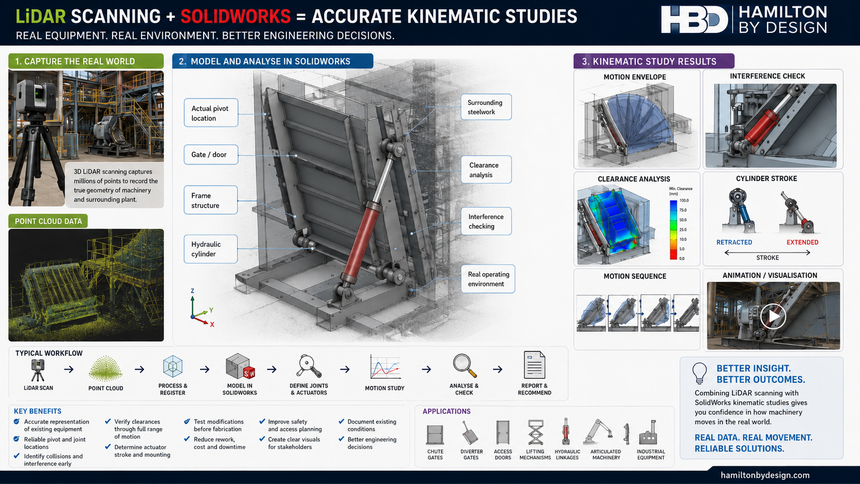
Infographic showing how LiDAR scanning and SOLIDWORKS are combined to create accurate kinematic studies, including point cloud capture, CAD modelling, motion analysis, interference checking, clearance analysis and actuator stroke review.

Combining LiDAR Scanning and SolidWorks for Kinematic Studies

Understanding how machinery moves within an existing industrial environment can be difficult when drawings are unavailable, outdated or do not reflect site modifications.

By combining 3D LiDAR scanning with SolidWorks, engineers can create kinematic studies based on the actual installed geometry of machinery, structures and surrounding plant. This provides a more reliable foundation for assessing movement, clearances, interference risks and proposed mechanical modifications.

What Is a Kinematic Study?

A kinematic study examines the movement of mechanical components without initially focusing on the forces that create that movement.

It may assess:

  • component position;
  • direction of movement;
  • travel distance;
  • angular rotation;
  • velocity;
  • acceleration;
  • linkage behaviour;
  • actuator stroke;
  • motion envelopes;
  • clearances between components;
  • potential collisions or interference.

Kinematic studies are commonly used for mechanical linkages, hydraulic cylinders, access doors, gates, chutes, diverters, lifting systems, articulated equipment and other moving machinery.

Why Existing Geometry Matters

A motion study is only as reliable as the geometry used to create it.

Many industrial machines have been modified, repaired or repositioned over time. Original drawings may no longer represent the actual equipment. Manual measurements may also be difficult where machinery is large, complex, elevated or surrounded by operating plant.

LiDAR scanning provides a detailed three-dimensional record of the equipment and its surroundings. The resulting point cloud can be used as a reference for developing an accurate SolidWorks model.

How LiDAR Scanning Supports the Study

A terrestrial LiDAR scanner records millions of measurement points across the visible surfaces of machinery, structures and plant.

The scan can help establish:

  • shaft and pivot locations;
  • hinge centres;
  • actuator mounting positions;
  • linkage lengths;
  • equipment orientation;
  • machine-frame geometry;
  • surrounding structural steel;
  • guards and access platforms;
  • nearby pipework;
  • operating clearances;
  • fixed obstructions.

This reduces reliance on assumptions and provides an engineering record of the existing condition at the time of capture.

How SolidWorks Is Used

Once the LiDAR data has been processed, the point cloud can be used to develop simplified or detailed SolidWorks models of the relevant machinery.

SolidWorks can then be used to:

  • create individual parts and assemblies;
  • locate pivots, shafts and mounting points;
  • define mechanical mates and joints;
  • simulate rotational and linear movement;
  • represent hydraulic-cylinder extension;
  • evaluate linkage positions;
  • calculate displacement, velocity and acceleration;
  • check component interference;
  • assess minimum clearances;
  • determine the swept path of moving equipment;
  • test proposed modifications before fabrication.

The surrounding plant can also be included as reference geometry so the machinery is analysed within its actual operating environment.

Typical LiDAR-to-SolidWorks Workflow

A typical workflow may include:

  1. Capture the machinery and surrounding plant using a LiDAR scanner.
  2. Register and process the scan data into a coordinated point cloud.
  3. Import or reference the point cloud within the CAD workflow.
  4. Identify the equipment required for the kinematic study.
  5. Create simplified SolidWorks models of the moving components.
  6. Position the models using the scanned geometry.
  7. Define mates, joints, travel limits and actuator movement.
  8. Run the SolidWorks motion study.
  9. Review clearances, collisions and movement envelopes.
  10. Develop recommendations, modifications or fabrication drawings.

Example: Hydraulic Chute Gate

A hydraulic chute gate may include a gate plate, pivot shaft, support frame and hydraulic cylinder.

A LiDAR scan can capture:

  • the existing chute geometry;
  • the gate position;
  • the pivot-shaft location;
  • upper and lower cylinder mounts;
  • surrounding structural steel;
  • platforms, guards and walkways;
  • nearby services and obstructions.

The geometry can then be recreated in SolidWorks to assess:

  • the gate opening angle;
  • the required cylinder stroke;
  • the relationship between cylinder travel and gate rotation;
  • potential dead-centre positions;
  • interference with the chute or surrounding steelwork;
  • clearances through the full operating cycle;
  • whether a proposed replacement cylinder will fit;
  • whether revised mounting points will improve movement.

This allows potential problems to be identified before components are manufactured or installed.

Collision and Interference Assessment

One of the main advantages of combining LiDAR with SolidWorks is the ability to assess moving machinery against the real site environment.

A standalone CAD model may show that a mechanism operates correctly. However, it may not reveal that the moving equipment could contact:

  • an existing handrail;
  • a structural beam;
  • electrical cable trays;
  • nearby pipework;
  • a maintenance platform;
  • machine guarding;
  • adjacent equipment.

By modelling the mechanism within the scanned environment, these conflicts can be identified before shutdown, fabrication or installation.

Evaluating Hydraulic Cylinders and Actuators

SolidWorks motion studies can assist with assessing actuator geometry, including:

  • extended and retracted cylinder lengths;
  • required stroke;
  • cylinder mounting angles;
  • connection-point movement;
  • mechanical advantage;
  • actuator alignment;
  • over-travel;
  • end-of-stroke position;
  • potential side loading;
  • approach to dead-centre conditions.

Where forces and loads must also be evaluated, the kinematic model may be expanded into a dynamic motion or structural assessment using suitable engineering inputs.

Benefits for Brownfield Engineering

LiDAR and SolidWorks are particularly valuable for brownfield projects where machinery must be modified within an existing facility.

The combined workflow can provide:

  • improved confidence in existing dimensions;
  • reduced dependence on outdated drawings;
  • fewer manual site measurements;
  • improved identification of site constraints;
  • better interference detection;
  • more reliable actuator selection;
  • improved design coordination;
  • reduced fabrication rework;
  • better shutdown planning;
  • clearer communication with stakeholders;
  • visual animations of proposed movement;
  • a documented digital record of existing conditions.

Static Scanning and Multiple Equipment Positions

A conventional terrestrial LiDAR scanner generally captures static geometry rather than continuously recording fast mechanical movement.

For this reason, equipment may be scanned in several controlled positions, such as:

  • fully closed;
  • partially open;
  • fully open;
  • maintenance position;
  • parked position.

These positions can be compared and used to confirm the geometry and range of movement.

Where actual operating speed or time-dependent behaviour is required, LiDAR data may be combined with:

  • video footage;
  • shaft encoders;
  • linear displacement sensors;
  • accelerometers;
  • control-system data;
  • hydraulic pressure records;
  • machine operating logs.

From Kinematic Study to Engineering Deliverables

The SolidWorks model developed from the LiDAR data can support more than the motion study itself.

Potential deliverables may include:

  • existing-condition 3D models;
  • kinematic study reports;
  • movement-envelope drawings;
  • interference reports;
  • clearance assessments;
  • actuator-stroke calculations;
  • SolidWorks motion animations;
  • general arrangement drawings;
  • modification concepts;
  • fabrication drawings;
  • installation planning models;
  • shutdown work packs;
  • stakeholder presentation images.

Applications

LiDAR-supported kinematic studies may be suitable for:

  • chute gates;
  • diverter gates;
  • conveyor take-up systems;
  • hydraulic linkages;
  • access doors;
  • lifting mechanisms;
  • maintenance hatches;
  • articulated machinery;
  • robotic systems;
  • positioning equipment;
  • stackers and reclaimers;
  • mobile plant attachments;
  • mechanical dampers;
  • valve-actuation systems;
  • machine guarding;
  • equipment relocation projects.

A More Reliable Basis for Mechanical Design

Combining LiDAR scanning with SolidWorks allows a kinematic study to be developed around the actual machine and the actual site environment.

LiDAR captures the existing geometry. SolidWorks converts that information into an intelligent mechanical model that can be moved, tested and reviewed.

Together, these tools can help engineers identify movement restrictions, confirm actuator requirements, assess clearances and test proposed modifications before work reaches fabrication or site installation.

LiDAR Scanning and SolidWorks Support

Hamilton By Design provides engineer-led 3D LiDAR scanning, point-cloud processing, SolidWorks modelling and mechanical design support for existing industrial machinery and brownfield facilities.

Our services can assist with:

  • existing-condition capture;
  • reverse engineering;
  • SolidWorks assembly modelling;
  • kinematic studies;
  • motion-envelope assessments;
  • interference checking;
  • actuator and linkage reviews;
  • mechanical modifications;
  • fabrication drawings;
  • installation planning.

For assistance with a kinematic study, machinery modification or LiDAR-based SolidWorks model, contact Hamilton By Design to discuss the equipment, required movement and project objectives.

Hamilton By Design logo displayed on a blue tilted rectangle with a grey gradient background

Contact Us – Talk To Us

Name
Would you like us to arrange a phone consultation for you?
Address

Our clients:


LiDAR Scanning for Mining and Industrial Shutdowns

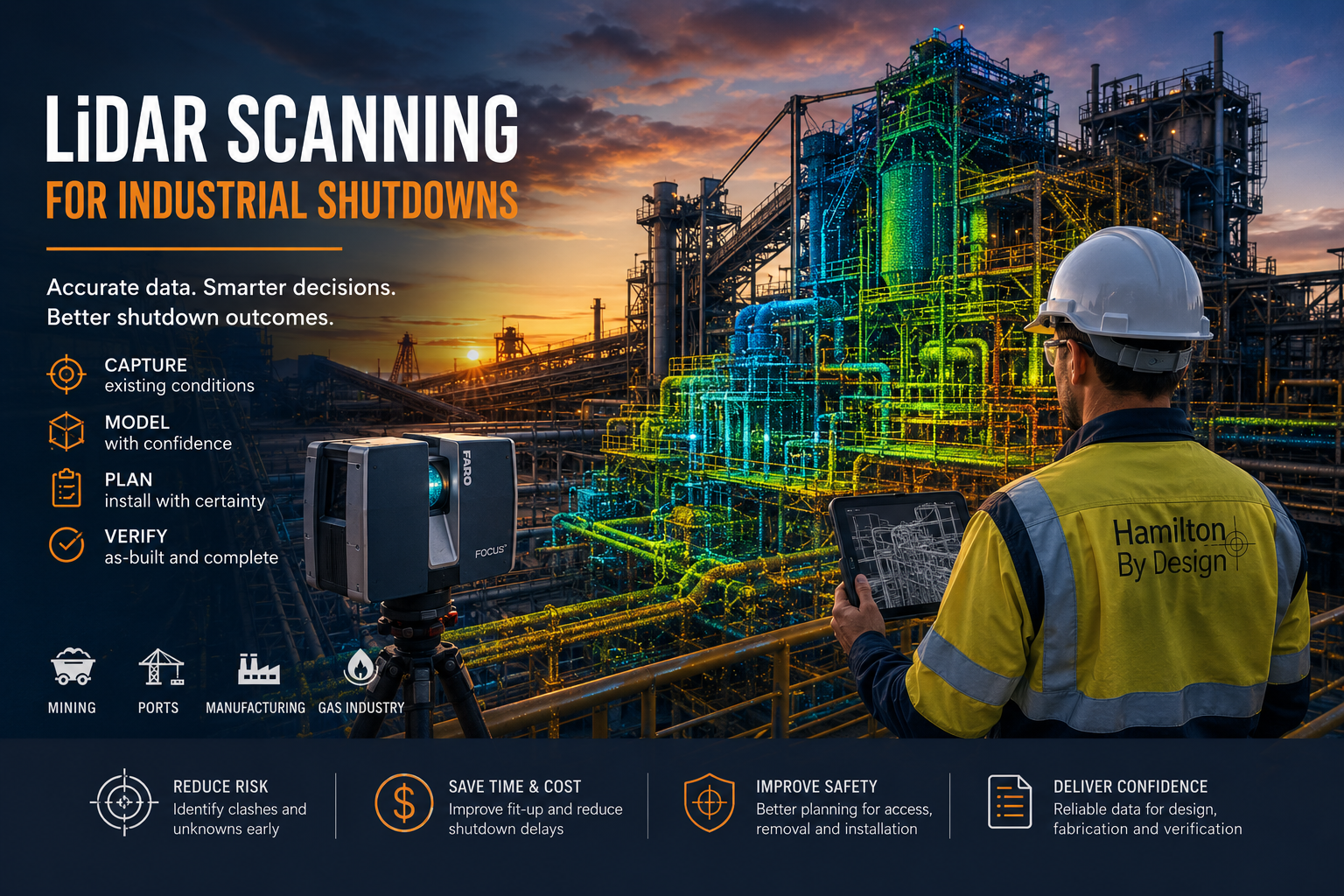
Engineer using a FARO LiDAR scanner to capture an industrial plant during a planned shutdown for design, fabrication and as-built verification.

LiDAR Scanning for Industrial Shutdowns: Reducing Risk Across Mining, Ports, Manufacturing and Gas Facilities

Industrial shutdowns provide a limited opportunity to inspect, modify, repair and replace critical plant and infrastructure. Every activity must be carefully planned because unexpected site conditions, inaccurate drawings or poorly fitting components can delay the restart of an entire operation.

LiDAR scanning can reduce this uncertainty by capturing a detailed three-dimensional record of the plant before or during the shutdown. The resulting point-cloud data can support engineering design, fabrication, installation planning, clash detection and final as-built verification.

Hamilton By Design provides engineering-grade 3D laser scanning for mining and industrial plants, combining site capture with practical mechanical engineering, CAD modelling and fabrication experience.

Rather than treating scanning as a standalone surveying activity, the objective is to collect the right information for the engineering decisions that follow.

Why Accurate Existing-Condition Data Matters During a Shutdown

Shutdown projects often involve brownfield plant that has been modified repeatedly over many years. Existing drawings may be incomplete, outdated or inconsistent with the current installation.

Small dimensional discrepancies can create major problems when replacement equipment, structural steel, pipe spools, platforms or mechanical components arrive on site. Typical problems include:

  • Bolt holes that do not align
  • Pipe flanges with incorrect positions or orientations
  • Structural members that clash with existing services
  • Replacement equipment that cannot pass through the planned access route
  • Platforms or stairs that interfere with nearby plant
  • Insufficient crane, rigging or installation clearances
  • Fabricated components that require modification on site

These problems are particularly costly during a shutdown because labour, cranes, contractors and production schedules have already been committed.

LiDAR scanning helps establish a reliable geometric record of what is actually present. Millions of spatial measurements are collected to form a point cloud representing equipment, structures, pipework, access systems and surrounding plant.

This data can then be referenced during design and reviewed before fabrication begins.

Scanning Before, During and After a Shutdown

LiDAR scanning can be used at several stages of the shutdown lifecycle.

Pre-shutdown scanning

Scanning before the shutdown allows the project team to develop a detailed understanding of the existing plant while there is still time to resolve design issues.

Pre-shutdown scanning can support:

  • Existing-condition verification
  • Scope development
  • Mechanical and structural design
  • Pipework and flange tie-in verification
  • Equipment replacement planning
  • Clash detection
  • Removal and installation studies
  • Crane and rigging access reviews
  • Fabrication of replacement components
  • Constructability reviews

Where the plant remains operational, the scanning plan must consider moving equipment, restricted access, line-of-sight limitations and operational safety requirements.

Scanning during the shutdown

Some areas cannot be captured while the plant is operating. Guards, covers, liners, access panels and equipment components may need to be removed before the relevant geometry becomes visible.

Shutdown scanning can capture:

  • Internal chute geometry
  • Hidden equipment interfaces
  • Wear surfaces
  • Equipment mounting points
  • Flange faces and pipework connections
  • Internal vessel or tank conditions
  • Structural connections
  • Areas normally obstructed by operating equipment

This information can assist with unexpected conditions identified after isolation and disassembly.

Post-installation scanning

A final scan can provide an independent record of completed work. It may be used to verify equipment location, clearances, structural geometry and the final arrangement of modified plant.

Post-installation data can also support drawing updates, asset records and future maintenance planning.

LiDAR Scanning for Mining Shutdowns

Mining and mineral-processing facilities contain complex combinations of conveyors, chutes, crushers, screens, pumps, tanks, pipework and structural steel. These assets may operate continuously, leaving only short periods for major inspections and modifications.

Hamilton By Design provides dedicated 3D scanning for mining shutdown projects where reliable existing-condition information is required for plant upgrades and replacement works.

Typical mining shutdown applications include:

  • Chute and transfer-station replacement
  • Conveyor upgrades and realignment
  • Crusher and screen replacement
  • Pump and piping modifications
  • Hopper and bin refurbishment
  • Wear-liner replacement
  • Structural steel modifications
  • Platform, stair and handrail upgrades
  • Equipment foundation verification
  • Brownfield plant expansions

For a chute replacement, for example, the scan can capture the inlet and discharge interfaces, surrounding structural steel, conveyor geometry, pulley locations, maintenance access and nearby services.

The replacement chute can then be designed within the scanned environment, reducing reliance on isolated manual dimensions or outdated drawings.

LiDAR Scanning for Ports and Bulk Materials Handling

Ports and export terminals often contain large mobile and fixed assets operating around restricted shipping and loading schedules. Access may involve work at height, over water or around active bulk-materials-handling equipment.

LiDAR scanning can support shutdown and maintenance work involving:

  • Ship loaders and unloaders
  • Conveyors and transfer towers
  • Hoppers and loading chutes
  • Gantries and structural frames
  • Wharf infrastructure
  • Rail-mounted equipment
  • Maintenance platforms
  • Access stairs and walkways
  • Hydraulic and mechanical systems
  • Pipework and services

Scanning is particularly useful when a project requires an understanding of the relationship between multiple systems rather than one isolated dimension.

A ship-loader modification, for example, may require verification of structural geometry, conveyor interfaces, maintenance clearances, access routes and the position of nearby equipment. Capturing these elements within one coordinated point cloud gives designers a broader understanding of the installation environment.

It can also reduce repeated site visits and the amount of time personnel need to spend in difficult-access areas.

LiDAR Scanning for Manufacturing Shutdowns

Manufacturing facilities commonly schedule maintenance and installation work over weekends, public holidays or planned production shutdowns. The available period may be extremely limited, and a delayed restart can affect production targets, customers and downstream operations.

Applications include:

  • Production-line modifications
  • New machinery installation
  • Equipment relocation
  • Ducting and extraction upgrades
  • Process-pipework modifications
  • Utility-routing studies
  • Machine guarding
  • Platforms and access systems
  • Equipment foundation verification
  • Factory layout documentation

LiDAR scanning can capture the relationship between machinery, building structures, overhead services, pipework, platforms and access areas.

This is valuable when new equipment is being designed or supplied before the existing machinery is removed. The proposed installation can be modelled within the scanned environment to identify possible clashes and confirm maintenance access.

Scanning can also document areas that become visible only when the production line is shut down, cleaned or partially dismantled.

LiDAR Scanning for Gas and Process Facilities

Gas and process facilities require careful management of brownfield interfaces, hazardous areas, permits, isolation requirements and engineering records.

Common scanning applications include:

  • Pipe-rack documentation
  • Brownfield piping tie-ins
  • Flange-position verification
  • Valve and instrument access studies
  • Vessel and skid replacement
  • Nozzle-position verification
  • Pipe-support modifications
  • Structural framing upgrades
  • Removal and installation-path studies
  • As-built documentation

Where pipe spools are fabricated before a shutdown, accurate tie-in information is essential. The position, angle and orientation of each connection must be correctly understood.

LiDAR scanning can provide a detailed spatial reference for pipework and surrounding plant. However, critical flange faces, bolt patterns and connection details may also require verification using traditional measurement methods or appropriate survey controls.

Scanning should therefore form part of a fit-for-purpose measurement strategy rather than being applied without consideration of the required tolerance.

From Point Cloud to Engineering Deliverables

A point cloud is a valuable source of information, but it is not automatically an engineering solution.

The required deliverables should be established before scanning begins. Hamilton By Design integrates scanning with SMP project delivery and brownfield engineering workflows so that the captured data can be converted into information suited to the project.

Potential deliverables include:

  • Registered E57, RCP, RCS or LAS point clouds
  • Existing-condition CAD models
  • SolidWorks or Inventor assemblies
  • STEP, SAT or Parasolid geometry
  • AutoCAD plans and layouts
  • General arrangement drawings
  • Plans, sections and elevations
  • Fabrication-reference models
  • Pipe and flange interface records
  • Clash-detection models
  • Existing-condition reports
  • Redline and as-built drawing updates

The required modelling level should reflect the intended use. A broad plant-layout study may only require simplified geometry, while a shutdown-critical fabricated component may require more detailed modelling and verification of specific interfaces.

Planning a Fit-for-Purpose Shutdown Scan

A successful scan begins with a clear understanding of the project problem.

Before mobilising, the scanning team should consider:

  • What is being designed, replaced or inspected?
  • Which dimensions and interfaces are critical?
  • What equipment will be operating?
  • What becomes accessible only during the shutdown?
  • What scan density and coverage are required?
  • Are survey controls required?
  • Are there hazardous-area restrictions?
  • Will dust, steam, rain or reflective surfaces affect capture?
  • What file formats are required?
  • What CAD or drawing deliverables will be produced?

The scanning envelope should include more than the immediate component. Surrounding structures, services, access routes and potential clash points may be equally important.

Hamilton By Designโ€™s broader engineering services allow scanning information to be reviewed in the context of mechanical design, plant modifications, constructability and fabrication requirements.

Frequently Asked Questions

Can LiDAR scanning be completed while the plant is operating?

Yes, in many situations. However, moving machinery, mobile equipment, dust, restricted access and safety requirements must be considered. Some areas may need to be captured after isolation or during the shutdown.

How accurate is industrial LiDAR scanning?

Accuracy depends on the scanner, distance, environment, registration method, surface condition and required deliverable. The project tolerance should be established before scanning. Critical interfaces may require additional verification.

Can scanning prevent fabricated components from not fitting?

Scanning can significantly reduce fit-up risk by providing accurate existing-condition geometry. It cannot eliminate every risk, particularly where surfaces are hidden or project tolerances have not been properly defined.

What can be scanned during a mining shutdown?

Typical assets include conveyors, chutes, crushers, screens, hoppers, pipework, tanks, equipment bases, platforms, stairs, handrails and structural steel.

Can point-cloud data be converted into CAD?

Yes. Relevant geometry can be converted into SolidWorks, Inventor or AutoCAD models and drawings. The amount of modelling required depends on the intended engineering use.

Does every part of the point cloud need to be modelled?

No. Modelling the entire environment may add unnecessary cost and time. A fit-for-purpose model should focus on the equipment, structures and interfaces needed for the project.

Can scanning be used for pipework tie-ins?

Yes. It can capture pipe routes, surrounding structures, supports and connection locations. Critical flange and tie-in details should be verified to the accuracy required for fabrication.

When is the best time to complete the scan?

Where possible, an initial scan should be completed early enough to support design and fabrication. Additional scanning may be undertaken during the shutdown when hidden areas become accessible.

Reduce Shutdown Uncertainty with Engineering-Led LiDAR Scanning

The primary value of LiDAR scanning during a shutdown is not simply the speed of measurement. Its value comes from reducing uncertainty before fabrication and installation begin.

By capturing the plant accurately, project teams can identify clashes, verify interfaces, plan access and develop modifications against the actual site environment.

For mining, ports, manufacturing and gas facilities, engineering-led LiDAR scanning can support safer planning, improved fit-up and a more controlled return to operation.

Contact Hamilton By Design to discuss the scanning envelope, required accuracy, site conditions and engineering deliverables for your next shutdown project.

Hamilton By Design logo displayed on a blue tilted rectangle with a grey gradient background

Contact Us – Talk To Us

Name
Would you like us to arrange a phone consultation for you?
Address

Our clients:


3D Laser Scanning for Hunter Valley CHPP Engineering

Infographic titled โ€œ3D Laser Scanning and Existing-Condition Study โ€“ Hunter Valley Coal Handling and Preparation Plant,โ€ showing an industrial CHPP with conveyors, transfer stations, chutes, platforms and pipework, alongside a LiDAR scanner, a colour point-cloud view, key project challenges, deliverables, workflow steps and engineering outcomes.

3D Laser Scanning and Existing-Condition Study for a Hunter Valley CHPP

Project Overview

Blue line icon of a tripod-mounted LiDAR scanner capturing the side profile of a mining haul truck.

Hamilton By Design completed an engineering-grade 3D laser scanning and existing-condition study for a coal handling and preparation plant in the Hunter Valley, New South Wales.

The study was undertaken to capture the installed condition of the plant before proposed mechanical and structural modifications were developed.

The scanning area included conveyors, transfer stations, chutes, structural steelwork, access platforms, pipework and surrounding equipment.

The plant had undergone changes over time, and the available drawings did not fully represent the current installed condition.

The Engineering Challenge

Coal handling and preparation plants contain complex mechanical, structural and materials-handling systems.

Equipment is often installed within congested areas where conveyors, pipework, platforms, structural supports and electrical services pass through the same working space.

The proposed modifications needed to connect accurately with the existing plant.

The main project risks included:

  • incomplete or outdated drawings
  • restricted access around operating equipment
  • complex chute and conveyor geometry
  • elevated plant structures
  • limited shutdown periods
  • difficult-to-measure equipment interfaces
  • uncertainty around existing clearances
  • potential clashes with structural steelwork and services
  • fabrication errors caused by incorrect dimensions

A conventional site measure would have captured only selected dimensions and could have missed important obstructions or plant interfaces.

Scope of Work

Hamilton By Design completed the following work:

  • reviewed the available plant drawings and project information
  • defined the required scanning envelope
  • planned suitable scanner positions
  • completed terrestrial 3D laser scanning throughout the nominated CHPP area
  • captured conveyors, chutes, transfer stations and supporting structures
  • captured platforms, stairs, handrails, pipework and surrounding services
  • registered and quality-checked the scan data
  • prepared a coordinated existing-condition point cloud
  • extracted critical equipment and structural dimensions
  • reviewed clearances and installation constraints
  • supported the development of the proposed mechanical modifications

3D Laser Scanning Methodology

The plant area was reviewed before scanning to identify the most important mechanical, structural and installation interfaces.

Multiple scanner positions were used to capture the plant from different directions and reduce hidden areas within the point cloud.

The scan coverage included:

  • conveyor head and tail sections
  • transfer chutes
  • discharge points
  • hoppers and bins
  • support frames
  • platforms and walkways
  • stairs and handrails
  • pipework and services
  • floor and structural levels
  • surrounding mechanical equipment
  • maintenance-access areas
  • proposed installation paths

The individual scans were registered into a single coordinated point cloud.

The completed dataset was checked for alignment, coverage and suitability for engineering use before detailed design work commenced.

Existing-Condition Information Captured

Blue 3D LiDAR scanner icon on a tripod with scanning waves

The registered point cloud provided a detailed three-dimensional record of the CHPP area.

The scan data allowed the engineering team to confirm:

  • installed conveyor positions
  • chute and hopper geometry
  • structural support locations
  • platform and walkway arrangements
  • pipework routes
  • equipment connection points
  • floor and structural elevations
  • maintenance clearances
  • removal and installation envelopes
  • potential clashes with existing plant

This information provided a reliable basis for developing the proposed modifications.

Engineering Deliverables

The project deliverables included:

  • a registered engineering-grade point cloud
  • E57 point-cloud files
  • Autodesk-compatible point-cloud files
  • extracted site dimensions
  • existing-condition geometry
  • equipment interface locations
  • structural interface locations
  • clearance and clash-review information
  • supporting views for mechanical design and drafting

The point-cloud data could also be used to prepare:

  • SolidWorks models
  • Autodesk Inventor models
  • STEP and SAT files
  • general arrangement drawings
  • sections and elevations
  • fabrication drawings
  • installation drawings
  • demolition drawings
  • shutdown work packs

Engineering Outcome

The completed existing-condition study gave the project team a reliable spatial reference for the proposed CHPP modifications.

Differences between the available drawings and the actual installed plant could be identified before detailed design and fabrication progressed.

The point cloud allowed the mechanical design to be developed around the real plant condition rather than assumed dimensions.

The scan data supported:

  • conveyor modification design
  • chute replacement and redesign
  • transfer-point upgrades
  • structural support modifications
  • new platform and access design
  • pipework rerouting
  • equipment replacement planning
  • clash detection
  • mechanical fit-up verification
  • maintenance-access reviews
  • fabrication planning
  • shutdown installation sequencing

Benefits to the Client

The use of engineering-grade 3D laser scanning provided several practical benefits:

  • reduced reliance on outdated drawings
  • faster capture of complex CHPP geometry
  • fewer manual measurements
  • reduced need for return site visits
  • improved confidence in the mechanical design
  • earlier identification of potential clashes
  • lower risk of fabrication errors
  • reduced risk of shutdown installation delays
  • improved coordination between engineering and site teams
  • better planning of equipment removal and installation
  • creation of a reusable digital record of the plant

Why 3D Laser Scanning Was Suitable

3D laser scanning was well suited to the project because the engineering work depended on an accurate understanding of the existing plant arrangement.

A CHPP can contain hundreds of interacting mechanical, structural and service components within a relatively small area.

The point cloud allowed a large amount of spatial information to be captured during a controlled site visit.

Engineers and designers could then review the plant remotely, inspect equipment interfaces and take additional measurements without repeatedly returning to site.

This provided a more complete engineering reference than a limited set of manually recorded dimensions.

Conclusion

The project demonstrated the value of 3D laser scanning for brownfield engineering within Hunter Valley coal handling and preparation plants.

By capturing the existing plant before detailed design and fabrication, Hamilton By Design reduced uncertainty and improved the quality of the engineering information available to the project team.

Engineering-grade LiDAR can provide a reliable foundation for:

  • conveyor upgrades
  • chute and transfer-station modifications
  • equipment replacement
  • structural modifications
  • platform and access upgrades
  • pipework modifications
  • reverse engineering
  • as-built verification
  • mechanical fit-up
  • shutdown planning
  • digital-twin development

Accurate existing-condition data allows CHPP modifications to proceed with greater confidence and a lower risk of site-related design changes.


Hamilton By Design logo displayed on a blue tilted rectangle with a grey gradient background

Contact Us – Talk To Us

Name
Would you like us to arrange a phone consultation for you?
Address

Our clients:
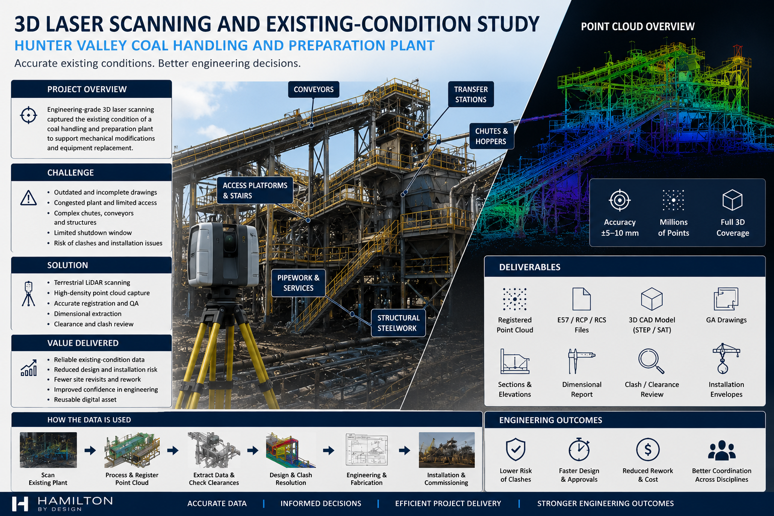

Scan to BIM Services Australia | 3D Laser Scanning

Hamilton By Design engineer using a 3D laser scanner to capture an industrial plant, transitioning from the existing facility through a point cloud into an accurate BIM model.

Scan to BIM Services for Industrial and Engineering Projects

Blue 3D LiDAR scanner icon on a tripod with scanning waves

Hamilton By Design provides engineering-led Scan to BIM services, combining accurate 3D laser scanning, point-cloud processing and BIM modelling to document existing buildings, industrial plants, infrastructure and engineering assets.

Our services help engineers, asset owners, architects, contractors, fabricators and project managers work from reliable existing-condition information rather than relying solely on outdated drawings, incomplete asset records or manual site measurements.

From the initial site survey through to the completed digital model, Hamilton By Design can provide an integrated workflow covering:

  • 3D laser scanning
  • LiDAR reality capture
  • Point-cloud registration and processing
  • Existing-condition surveys
  • Scan to CAD conversion
  • Scan to BIM modelling services
  • Mechanical and structural modelling
  • As-built verification
  • Design coordination
  • Engineering documentation
  • Asset information development

Our practical industrial and engineering experience allows us to capture and model complicated environments where access, safety, accuracy and constructability are critical.

What Are Scan to BIM Services?

Scan to BIM is the process of capturing an existing building, facility or industrial asset using terrestrial LiDAR or 3D laser scanning and converting the resulting point cloud into a structured Building Information Model.

A laser scanner records millions of measurable points across the surfaces visible from each scanning position. These individual scans are registered together to produce a coordinated three-dimensional point cloud representing the existing site.

The point cloud can then be used to develop an appropriate digital model containing architectural, structural, mechanical or building-services elements.

Depending on the requirements of the project, the completed BIM model may include:

  • Building structures and architectural elements
  • Structural steel framing
  • Platforms, stairs and access structures
  • Industrial equipment
  • Conveyors, chutes and transfer stations
  • Tanks, vessels and pump systems
  • Pipework and ductwork
  • Plant rooms and service routes
  • Electrical and mechanical equipment locations
  • Existing penetrations and connection points
  • Access restrictions and physical obstructions

The required model content, accuracy and level of detail should be established before modelling begins. This helps ensure that the final model is suitable for its intended engineering, construction, coordination or asset-management purpose.

Hamilton By Design provides Scan to BIM services across Australia for industrial, infrastructure, commercial and engineering projects requiring accurate existing-condition information.

Engineering-Led 3D Laser Scanning

Our 3D laser scanning services are delivered with an understanding of how the captured information will be used during design, fabrication, installation and maintenance.

A visually impressive point cloud is not enough. The scanning plan must capture the interfaces that matter to the project.

These interfaces may include:

  • Equipment mounting points
  • Structural connections
  • Pipe and duct routes
  • Flange locations and orientations
  • Existing steel members
  • Floor and platform levels
  • Clearances around machinery
  • Fabrication interfaces
  • Potential installation paths
  • Areas where clashes could occur

Scanning from multiple coordinated positions reduces shadows and improves coverage around complicated geometry. The resulting registered point cloud can then be reviewed before modelling begins.

This approach is particularly valuable for brownfield projects, where the existing installation may no longer match the original drawings.

Professional 3D Laser Scanning Services

Professional 3D laser scanning services provide a faster and more comprehensive method of documenting complicated facilities than relying solely on tape measures, photographs and manually recorded dimensions.

Laser scanning can support:

  • Existing-condition documentation
  • Brownfield plant upgrades
  • Equipment replacement
  • Structural modifications
  • Shutdown planning
  • Construction coordination
  • Fabrication verification
  • Clash detection
  • Reverse engineering
  • Asset-management projects
  • Refurbishment and redevelopment
  • Digital engineering workflows

The scanner captures surrounding geometry rather than only the dimensions initially identified during the site visit. This provides a more complete digital record that can be reviewed after the survey and may reduce the need for repeated site measurements.

However, appropriate planning remains important. Areas hidden behind equipment, insulation, cladding or other obstructions cannot automatically be captured. Critical interfaces should therefore be identified during the planning stage so that suitable scanner positions can be selected.

Industrial 3D Scanning Service

Hamilton By Design provides an industrial 3D scanning service for mining, manufacturing, processing, materials-handling, utilities and infrastructure environments throughout Australia.

Industrial sites present different challenges from conventional building surveys. They often contain congested equipment, restricted access, elevated structures, moving machinery, reflective surfaces and complicated interconnecting services.

Our industrial 3D scanning services can be used to capture:

  • Processing plants
  • Manufacturing facilities
  • Conveyor systems
  • Transfer stations
  • Chutes and hoppers
  • Pump stations
  • Tanks and vessels
  • Pipe racks
  • Structural steel
  • Platforms and walkways
  • Plant rooms
  • Workshops and warehouses
  • Ports and terminals
  • Water and wastewater infrastructure
  • Mining and mineral-processing facilities

The captured data can support mechanical engineering, structural modifications, replacement-equipment design, fabrication detailing, site coordination and future maintenance planning.

Because Hamilton By Design combines reality capture with engineering and drafting capability, the point cloud can be developed into practical project deliverables rather than being supplied only as raw scanning data.

Scan to BIM Modelling Services

Our Scan to BIM modelling services convert registered point-cloud information into usable digital models that reflect the existing asset.

The modelling scope can be adjusted to suit the intended project outcome.

For example, a building-services coordination project may require walls, floors, columns, ceilings, ducts, pipes and major equipment. An industrial modification project may instead require detailed modelling around structural steel, mechanical equipment and fabrication interfaces.

Not every visible object needs to be modelled. Creating unnecessary geometry increases cost, model size and processing requirements without necessarily improving the project outcome.

Before beginning the modelling process, we work with the client to establish:

  • The intended use of the model
  • The required project coordinate system
  • Areas to be included
  • Critical interfaces
  • Required model accuracy
  • Required level of information
  • Appropriate level of detail
  • File formats and software requirements
  • Naming and information-management requirements
  • Quality-assurance and verification procedures

This purpose-driven approach helps ensure that the model is detailed where accuracy matters without adding unnecessary information.

Our Scan to BIM Workflow

1. Define the Project Requirements

The first step is to understand how the scan data and BIM model will be used.

The scope should identify the survey area, critical interfaces, accuracy expectations, modelling content and final deliverables.

For industrial projects, it is also important to identify operational restrictions, site-access requirements, shutdown periods and areas containing moving equipment.

2. Plan the Site Survey

Scanner positions are planned around physical access, line of sight, safety requirements and the complexity of the facility.

Additional scan positions may be required around congested machinery, structural connections, pipework and building services.

Where project coordinates or survey control are required, these requirements should be identified before scanning begins.

3. Complete the 3D Laser Scanning

The project area is captured using terrestrial LiDAR scanning equipment.

Site photographs, reference dimensions, survey control or additional field information may also be collected where required.

Scanning can be completed across individual rooms, buildings, industrial equipment, process areas or complete facilities.

4. Register and Process the Point Cloud

Individual scans are aligned into a coordinated point-cloud dataset.

The registration is reviewed, unnecessary information can be removed, and the completed dataset is prepared for modelling or engineering use.

The registered point cloud may also be issued as a standalone project deliverable.

5. Develop the BIM Model

The required architectural, structural, mechanical or building-services elements are modelled from the point cloud.

Model development is focused on the elements and interfaces relevant to the project requirements.

The project may require a complete BIM model or a more targeted model covering only the areas affected by the proposed work.

6. Verify the Model

The completed model is checked against the registered point cloud to identify departures from the captured geometry.

Critical dimensions, connection points and fabrication interfaces can receive additional attention during this stage.

Model verification helps establish confidence that the digital information represents the captured site conditions.

7. Issue the Deliverables

Depending on the project, deliverables may include:

  • Registered point clouds
  • E57 files
  • RCP or RCS files
  • LAS files
  • BIM models
  • Revit models
  • Navisworks coordination files
  • SolidWorks or Inventor models
  • STEP, SAT or Parasolid files
  • AutoCAD drawings
  • General arrangement drawings
  • Sections and elevations
  • As-built documentation
  • Clash-detection reports
  • Equipment and asset layouts

Benefits of Scan to BIM Services

More Reliable Existing-Condition Information

Scan to BIM provides a measurable digital record of the existing asset, reducing dependence on drawings that may no longer reflect site conditions.

Reduced Design Assumptions

Engineering and design teams can review actual geometry before developing new equipment, structures or services.

This can be particularly important where new components must connect to existing steelwork, pipework, ducting or mechanical equipment.

Improved Project Coordination

A coordinated digital model allows architectural, structural, mechanical and building-services teams to review the same existing-condition information.

Proposed designs can be incorporated into the model and reviewed against the captured site conditions.

Lower Rework Risk

Potential clashes, restricted clearances and access problems can be identified before fabrication or site installation begins.

Identifying these issues during the design stage can reduce costly changes during construction or shutdown work.

Better Shutdown Planning

Project teams can remotely review congested areas and prepare installation activities before a shutdown commences.

The point cloud can support planning for demolition, lifting, access, installation sequencing and new equipment positioning.

Improved Asset Information

The completed model can contribute to future maintenance planning, facility management and asset-information systems.

It can also provide a reliable starting point for future modifications and engineering investigations.

Reduced Site Measurement Requirements

Once the site has been captured, designers and engineers can inspect and measure many features remotely from the registered point cloud.

Although additional site verification may still be required for hidden or critical features, the digital dataset can substantially reduce repeated site visits.

Scan to BIM for Brownfield Projects

Brownfield industrial facilities frequently contain equipment and structures installed across several generations of modifications.

Original drawings may not show:

  • Later plant modifications
  • Replacement machinery
  • Rerouted pipework
  • Strengthened structural members
  • Added platforms
  • Temporary alterations
  • Changed access arrangements
  • Existing damage or deformation
  • Equipment installed during previous shutdowns

Using 3D laser scanning before design provides a reliable geometric reference for planning modifications around the facility as it currently exists.

Scan to BIM can be particularly valuable where new equipment must fit between existing structures, connect to existing systems or be installed during a limited shutdown period.

Rather than developing a design around assumed dimensions, the project team can use captured site geometry to improve coordination and constructability.

Scan to BIM for Industrial Facilities

Industrial Scan to BIM projects often require a different modelling approach from conventional architectural projects.

An industrial model may need to represent:

  • Mechanical equipment
  • Structural steel
  • Process pipework
  • Conveyors and chutes
  • Tanks and vessels
  • Platforms and access systems
  • Crane rails
  • Building structures
  • Electrical equipment
  • Ductwork and extraction systems
  • Existing fabrication interfaces

The importance of individual elements will depend on the purpose of the project.

For example, a conveyor modification may require detailed geometry around the conveyor structure, transfer chute, head pulley, supporting steelwork and access platform. Objects elsewhere in the building may only require simplified representation.

Defining the intended use of the model before scanning and modelling helps direct effort towards the areas that will influence the engineering outcome.

Scan to BIM and Point Cloud to CAD

A complete BIM model is not necessary for every engineering project.

For mechanical design, reverse engineering or fabrication work, a point-cloud-to-CAD workflow may be more appropriate.

Hamilton By Design provides Point Cloud to CAD services that convert captured site information into engineering-ready models and drawings.

Point Cloud to CAD deliverables may include:

  • Solid models
  • Surface models
  • Mechanical assemblies
  • Structural models
  • General arrangement drawings
  • Fabrication drawings
  • Interface geometry
  • Two-dimensional CAD documentation
  • Equipment layouts
  • Replacement-component models

Scan to BIM is generally more appropriate where the project requires structured building information, multidisciplinary coordination, model-based construction or lifecycle information management.

Point Cloud to CAD is often more suitable where the primary outcome is mechanical design, fabrication, replacement-equipment modelling or engineering documentation.

Hamilton By Design can help establish which approach is most appropriate for the required project outcome.

Scan to BIM Applications

Our Scan to BIM modelling services can support:

Industrial Plant Upgrades

Capture existing plant, equipment and supporting structures before designing modifications or replacement systems.

Mechanical Equipment Replacement

Record equipment interfaces, mounting points, service connections and available installation clearances.

Structural Modifications

Capture existing structural steel, platforms, access systems and connection locations before new structural elements are designed.

Building Refurbishment

Document existing building geometry, services and structural elements before refurbishment or redevelopment work begins.

Shutdown Projects

Create a digital record of the work area that can be used for remote planning, design coordination and installation preparation.

Fabrication Projects

Capture critical interfaces before fabrication drawings and workshop models are developed.

Asset Documentation

Create accurate existing-condition information to support ongoing maintenance, inspections and future engineering work.

Clash Detection

Coordinate proposed structures, equipment and services against the existing-condition model before construction begins.

Why Choose Hamilton By Design?

Hamilton By Design combines practical engineering experience with advanced reality-capture and three-dimensional modelling capability.

Our services are suitable for projects that require more than a basic visual survey. We focus on producing accurate, usable information that can support engineering decisions, fabrication, construction and asset management.

Our capability includes:

  • Engineering-led site capture
  • Terrestrial LiDAR scanning
  • Industrial point-cloud processing
  • Mechanical and structural modelling
  • Scan to CAD
  • Scan to BIM
  • Reverse engineering
  • SolidWorks and Inventor modelling
  • AutoCAD and engineering drafting
  • As-built verification
  • Fabrication-focused documentation
  • Engineering design support

We support projects throughout Sydney, Newcastle, the Central Coast, Hunter Valley, Brisbane, Melbourne, Perth, Adelaide, Darwin, Mount Isa and regional Australia.

Frequently Asked Questions

What are Scan to BIM services?

Scan to BIM services involve capturing an existing building, industrial facility or infrastructure asset using 3D laser scanning and converting the resulting point cloud into a structured Building Information Model.

The model can include architectural, structural, mechanical and building-services elements according to the requirements of the project.

What is the difference between 3D laser scanning and Scan to BIM?

3D laser scanning captures the existing asset and produces a measurable point cloud.

Scan to BIM takes the point-cloud information and converts the required existing elements into a structured digital model that can support design, coordination, construction or asset management.

What is included in a 3D laser scanning service?

A typical service may include site planning, LiDAR scanning, scan registration, point-cloud processing, data verification and delivery of the registered point cloud.

BIM modelling, CAD modelling, drawings and engineering documentation can be added according to the project requirements.

Can Hamilton By Design provide scanning without BIM modelling?

Yes. Registered point-cloud data can be supplied for use by the clientโ€™s own engineering, architectural, drafting or BIM team.

Point clouds may be provided in formats such as E57, RCP, RCS or LAS, depending on the intended software and workflow.

Can you convert an existing point cloud into a BIM model?

Yes, provided the point cloud has sufficient coverage, suitable accuracy and an accessible coordinate system.

The existing data should be reviewed before the modelling scope, cost and deliverables are confirmed.

What can be included in an industrial BIM model?

Industrial BIM models may include structural steel, platforms, stairs, equipment, conveyors, chutes, tanks, pipework, ductwork, buildings and other elements required for coordination or engineering design.

The modelling scope should focus on the elements that affect the project rather than attempting to model every visible object.

How accurate is Scan to BIM?

Accuracy depends on the scanning equipment, survey control, scan registration, site conditions, line of sight and modelling requirements.

The required accuracy and intended use of the model should be agreed before scanning and modelling commence.

Can Scan to BIM support fabrication?

Yes. Scan-derived models can establish existing interfaces, available clearances, structural locations and connection points.

Fabrication models and drawings can then be developed using verified existing-condition information.

Can Scan to BIM be used for clash detection?

Yes. Proposed equipment, structures, pipework, ductwork and services can be coordinated against the existing-condition model to identify potential spatial conflicts before construction or installation.

Is Scan to BIM suitable for brownfield industrial sites?

Yes. Scan to BIM is particularly useful for brownfield facilities where original drawings may be incomplete or may not reflect later modifications.

The point cloud provides a current geometric record of the accessible and visible site conditions.

Does laser scanning capture hidden objects?

No. Laser scanners capture surfaces that are visible from the scanner positions.

Objects hidden behind equipment, walls, insulation or cladding cannot be directly captured. Additional scanner positions, access openings or supplementary measurements may be required for critical concealed features.

Can the scan data be used in SolidWorks or Autodesk Inventor?

Yes. Point-cloud information can be used to develop mechanical models and assemblies for use in SolidWorks, Autodesk Inventor and other engineering CAD systems.

The most suitable conversion process depends on the type of equipment, the required model detail and the intended engineering outcome.

How long does a Scan to BIM project take?

The timeframe depends on the size and complexity of the site, access conditions, number of scans, required model detail and final deliverables.

A small project area may require a single day of scanning, while a complete industrial facility may require several days of site capture followed by point-cloud processing and modelling.

Do you provide Scan to BIM services throughout Australia?

Yes. Hamilton By Design supports industrial, engineering, infrastructure and commercial projects throughout metropolitan, regional and remote Australia.

Discuss Your Scan to BIM Project

Accurate existing-condition information can reduce uncertainty before design, fabrication and construction begin.

Hamilton By Design provides integrated Scan to BIM services, 3D laser scanning, 3D laser scanning services, industrial 3D scanning services and Scan to BIM modelling services for projects throughout Australia.

Contact Hamilton By Design to discuss:

  • The location and size of the site
  • The areas that need to be captured
  • The intended use of the model
  • Critical equipment and interfaces
  • Accuracy requirements
  • Required file formats
  • Project timeframes
  • Site-access and induction requirements
  • The most appropriate project deliverables

By defining the required outcome before scanning begins, we can develop a practical reality-capture and modelling workflow suited to your engineering, construction or asset-management requirements.

3D Laser Scanning Services

Hamilton By Design provides engineering-grade 3D laser scanning services for industrial plants, buildings, infrastructure and brownfield project environments. Our terrestrial LiDAR scanning captures accurate existing conditions to support design coordination, as-built documentation, fabrication planning and engineering modifications.

Explore our 3D Laser Scanning Services


Industrial 3D Scanning Services

Our industrial 3D scanning services are developed for complicated operational environments, including manufacturing plants, mining facilities, conveyors, chutes, structural steel, pipework, platforms and mechanical equipment. The captured point-cloud data can support plant upgrades, shutdown planning and replacement-equipment design.

Learn More About Industrial 3D Scanning Services


Point Cloud to CAD Australia

Hamilton By Design converts registered point-cloud data into practical engineering models and drawings. Deliverables can include SolidWorks models, Inventor models, AutoCAD drawings, general arrangements, sections, elevations and fabrication-ready interface geometry.

View Our Point Cloud to CAD Services


Mechanical and Digital Engineering Services

Our engineering services connect reality capture with mechanical design, structural modelling, engineering drafting and fabrication documentation. This integrated approach helps ensure that captured site information is converted into useful project deliverables rather than remaining as an isolated point-cloud dataset.

Explore Hamilton By Design Engineering Services

Hamilton By Design logo displayed on a blue tilted rectangle with a grey gradient background

Talk to Us – Contact Us

Name
Would you like us to arrange a phone consultation for you?
Address

Our clients: