


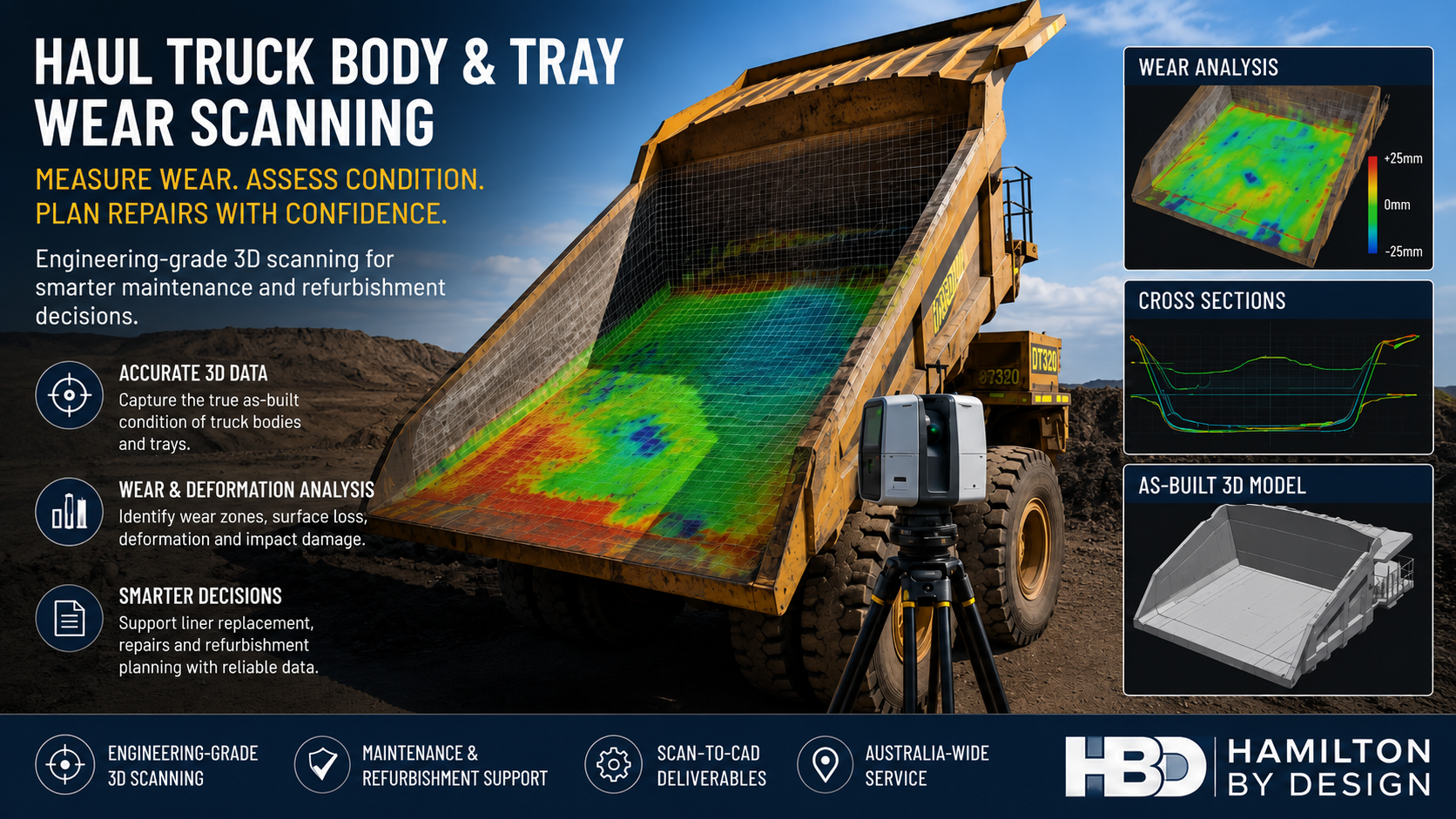
Haul Truck Body and Tray Wear Scanning
Measure Wear, Deformation and Liner Condition Before Repair or Refurbishment
Haul-truck bodies operate under repeated loading, abrasive material flow, impact and demanding mine-site conditions. Over time, the tray, tub or dump body can experience liner wear, localised thinning, deformation, cracking and changes to its original profile.
However, the full extent of this deterioration may be difficult to determine through visual inspection alone.
Hamilton By Design provides engineering-led haul truck body and tray wear scanning to capture the existing geometry of mining truck bodies and support informed maintenance, liner replacement and refurbishment decisions.
Using 3D laser scanning, we can document the internal and external surfaces of the truck body and produce an accurate digital record that can be reviewed, measured and compared against:
- Original equipment geometry
- Manufacturer drawings
- Previous scan data
- A nominal CAD model
- Known reference surfaces
- Adjacent areas of the same truck body
- Other bodies within the fleet
The resulting data helps maintenance teams establish where wear or deformation is occurring and determine whether the body should remain in service, receive local repairs, undergo liner replacement or be scheduled for a more extensive refurbishment.
What Is Haul Truck Tray Wear Scanning?
Haul truck tray wear scanning uses terrestrial 3D laser scanning or LiDAR technology to capture millions of measurement points across the surface of a mining truck body.
These measurements form a detailed point cloud representing the body’s current geometry.
Depending on the project requirements, the scan may include:
- The internal floor
- Sidewalls
- Front wall or headboard
- Canopy and spill protection
- Rear body structure
- External ribs and stiffeners
- Rock deflectors
- Body mounts and pivot areas
- Wear liners and liner interfaces
- Welded repairs and replacement plates
- Areas showing visible distortion or impact damage
The point-cloud data can then be converted into sections, surface models, deviation maps or engineering drawings for inspection and maintenance planning.
Hamilton By Design integrates 3D scanning directly into mechanical engineering and scan-to-CAD workflows, allowing the captured geometry to support practical design, inspection and upgrade decisions rather than remaining as standalone survey data.
The Maintenance Problem
Wear inside a haul truck body does not always occur evenly.
Material characteristics, payload distribution, loading technique, impact zones and material discharge patterns can create highly localised wear. Areas near the floor, transitions, sidewalls and rear discharge region may deteriorate at different rates.
Maintenance teams may know that a body is worn but may not have enough dimensional information to confidently answer questions such as:
- Which areas have experienced the greatest material loss?
- Is the floor still within an acceptable geometric condition?
- Are the sidewalls or front wall deforming?
- Has the tray changed shape due to repeated impact loading?
- Are replacement liners fitting against a distorted parent structure?
- Is the wear localised enough for a patch repair?
- Does the body require partial or complete relining?
- Is a refurbishment economically justified?
- Which areas should be monitored during the next inspection?
- Can the current scan be used as a baseline for future comparison?
Without reliable dimensional data, repairs may be based primarily on visual judgement, isolated thickness readings or assumptions about the original shape of the body.
Three-dimensional scanning provides a broader geometric record that can complement conventional inspection methods and help define the location, extent and pattern of deterioration.
What Can Be Assessed?
Tray Floor Wear
The tray floor is exposed to repeated impact, abrasion and sliding material during loading and discharge.
Scanning can identify:
- Local depressions
- Uneven floor profiles
- Buckling or distortion
- Worn liner zones
- Raised or poorly fitted repair plates
- Changes in floor slope
- Areas where material may hang up
- Differences between the left and right sides of the body
Where suitable reference geometry is available, the scanned floor can be compared with its expected or previous profile.
Sidewall and Front-Wall Deformation
Sidewalls and front walls can deform due to repeated loading, impact events, uneven payloads or structural deterioration.
A scan can help identify:
- Outward or inward bowing
- Localised dents
- Twisting
- Changes in wall angle
- Distortion near stiffeners
- Misalignment between wall sections
- Areas requiring closer structural inspection
Cross-sections can be taken through selected locations to quantify the body profile and assist with repair planning.
Liner Condition and Replacement Planning
Wear liners may become heavily worn, cracked, detached or distorted.
Three-dimensional scanning can document:
- Existing liner layout
- Liner plate boundaries
- Gaps between liner sections
- Raised edges and misalignment
- Localised wear pockets
- Previous replacement areas
- Interfaces between liners and parent structure
- Areas requiring new liner geometry
The scan data may also support the development of replacement liner drawings, templates or CAD models where existing documentation is unavailable or unreliable.
Body Distortion
A haul truck body may appear serviceable while having accumulated broader geometric distortion.
Scanning can be used to assess:
- Symmetry between both sides
- Overall body alignment
- Floor flatness
- Wall straightness
- Relative position of structural features
- Twist across the body
- Changes to discharge geometry
- Alignment of repaired sections
This information can help distinguish between local liner wear and more substantial deformation of the body structure.
Previous Repairs and Modifications
Mining truck bodies often accumulate welded repairs, patches, reinforcement plates and liner changes throughout their operating life.
A complete scan creates a digital record of those modifications and can help maintenance and engineering personnel identify:
- Non-original platework
- Overlapping repairs
- Added stiffeners
- Areas of repeated repair
- Changes from the nominal design
- Interfaces that may complicate future refurbishment
- Existing geometry that must be considered when designing new parts
Typical Scanning Workflow
1. Define the Inspection Objective
Before scanning, Hamilton By Design works with the maintenance or engineering team to establish the purpose of the assessment.
The scope may focus on:
- General condition documentation
- Tray floor wear
- Liner replacement
- Repair planning
- Deformation assessment
- Refurbishment scoping
- Comparison against a previous scan
- Reverse engineering of replacement components
- Investigation following an abnormal event
Defining the objective helps determine the required scan coverage, point density, reference measurements and final deliverables.
2. Prepare the Truck Body
For the clearest scan data, the body should be safely parked, isolated and made accessible.
Where practical, the scanning surfaces should be:
- Free from loose material
- Washed down
- Reasonably dry
- Accessible from several positions
- Presented with liners and repair areas visible
Heavy residual material can obscure the actual surface and may reduce the usefulness of the resulting wear assessment.
Site safety requirements, access conditions and isolation arrangements remain subject to the mine’s procedures.
3. Capture the Existing Geometry
Multiple scan positions are generally used to capture the internal and external geometry while reducing shadows and line-of-sight gaps.
The scanning plan may include:
- Ground-level external scans
- Internal body scans
- Elevated scan positions where safely available
- Detailed scans of critical wear zones
- Reference targets or control points
- Conventional verification measurements
Hamilton By Design provides engineering-grade 3D laser scanning for mining and industrial environments, including scan-to-CAD, structural verification and plant upgrade applications.
4. Register and Process the Point Cloud
The individual scans are registered into a coordinated point cloud.
The dataset can then be cleaned and organised to show:
- The complete body
- Internal wear surfaces
- External structure
- Critical repair areas
- Sections through selected zones
- Areas requiring further review
The point cloud becomes a permanent digital record of the body’s condition at the time of capture.
5. Compare the Geometry
Depending on the available information, the scan can be compared against:
- OEM CAD data
- Manufacturer drawings
- A nominal body profile
- A previously scanned condition
- A mirrored opposite side
- A fitted reference surface
- Another body of the same design
- Selected datums or known dimensions
Comparison outputs may include deviation colour maps, sections, dimensional tables and annotated images.
A colour deviation map can visually highlight where the scanned body lies above or below the chosen reference geometry.
6. Develop Maintenance Deliverables
The final outputs are selected according to the maintenance decision being supported.
These may include:
- Registered point-cloud data
- Existing-condition scan files
- Cross-sectional profiles
- Dimensional inspection drawings
- Surface deviation maps
- Wear-zone diagrams
- Annotated inspection images
- CAD surface models
- Replacement liner geometry
- Repair drawings
- Refurbishment concept models
- Scan-to-CAD models
- Baseline data for future monitoring
Baseline and Repeat Wear Scanning
One of the strongest applications for haul truck body scanning is repeat-condition monitoring.
An initial scan can establish a geometric baseline. A later scan can then be aligned with the baseline to identify changes that have occurred between inspections.
This may support:
- Monitoring of high-wear areas
- Comparison between maintenance intervals
- Review of liner performance
- Identification of changing deformation
- Assessment of repair effectiveness
- Improved refurbishment forecasting
- Comparison of wear patterns between trucks
- Planning of future shutdown work
For meaningful comparison, repeat scans should use a consistent scanning method, coordinate system and assessment procedure.
Where the required reference geometry is available and the scanning conditions are controlled, repeat scanning can provide a more systematic picture of how the body is changing over time.
Scanning Does Not Replace Thickness Testing
Three-dimensional laser scanning records visible surface geometry. It does not directly measure the remaining material thickness of an enclosed steel plate.
For that reason, haul truck body scanning may be combined with conventional inspection methods such as:
- Ultrasonic thickness testing
- Visual weld inspection
- Crack inspection
- Dye penetrant testing
- Magnetic-particle testing
- Structural engineering assessment
- Manufacturer inspection criteria
The strongest assessment may combine surface geometry from 3D scanning with plate-thickness measurements at selected locations.
The point cloud identifies where deformation and surface loss appear to be concentrated, while thickness testing can help establish the remaining plate or liner thickness.
Applications
Hamilton By Design’s haul truck body scanning service can support:
Planned Maintenance
Capture the body condition before a scheduled maintenance period and define the likely extent of liner or plate replacement.
Refurbishment Scoping
Document the existing body before issuing a repair or refurbishment scope to workshops and fabricators.
Liner Replacement
Capture the existing liner layout and supporting geometry before designing or manufacturing replacement liner components.
Repair Verification
Scan the body after repairs to document the completed geometry and verify selected dimensions.
Fleet Condition Comparison
Apply a consistent scanning process across multiple bodies to compare geometry, repairs and wear patterns.
Reverse Engineering
Create CAD geometry where original manufacturing information is missing, incomplete or no longer representative of the body.
Incident or Damage Investigation
Capture the body following an impact, overload event, structural concern or abnormal operating condition to preserve a dimensional record for engineering review.
Why Use Hamilton By Design?
Engineering-Led Data Capture
Hamilton By Design approaches scanning from a mechanical engineering and maintenance perspective.
The objective is not simply to produce a point cloud. The scan coverage is planned around the decision the client needs to make, such as whether to repair, reline, refurbish, redesign or continue monitoring the asset.
Practical Mining and Heavy-Industry Experience
Hamilton By Design supports mining and mineral-processing operations with engineering-grade LiDAR scanning, mechanical design, reverse engineering and drafting for plant, materials-handling equipment and brownfield modifications.
This practical background helps ensure the scan captures relevant interfaces, repair areas and structural features.
Scan-to-CAD Capability
Where required, the point cloud can be developed into:
- 3D CAD models
- Surface geometry
- Replacement components
- General-arrangement drawings
- Sections and profiles
- Fabrication drawings
- Repair concepts
- Refurbishment documentation
This allows the same captured dataset to support inspection, engineering and fabrication activities.
Reduced Reliance on Assumptions
Existing truck bodies may differ from their original drawings because of wear, damage, modifications and previous repairs.
Scanning captures the body as it currently exists, helping reduce reliance on nominal dimensions or outdated records.
Australia-Wide Support
Hamilton By Design provides 3D laser scanning services across Australia, including mining and industrial regions in New South Wales, Queensland, Western Australia, Victoria, South Australia and the Northern Territory.
Mobilisation to regional and remote mining operations can be discussed as part of the project scope.
Information Required for a Quotation
To prepare a scope and quotation, the following information is helpful:
- Haul truck manufacturer and model
- Body, tray or tub manufacturer
- Number of truck bodies to be scanned
- Mine or workshop location
- Whether the body can be washed down
- Internal and external access conditions
- Areas of known wear or deformation
- Available OEM drawings or CAD models
- Previous scan or inspection records
- Required deliverables
- Site-access and induction requirements
- Planned maintenance or shutdown dates
- Whether thickness testing data is available
- Whether replacement liner or repair design is required
Photographs of the body and the surrounding access area can also help define the required scanning setup.
Frequently Asked Questions
Is a haul truck tray also called a tub or dump body?
Yes. Terminology varies across mining operations, manufacturers and regions. The assembly may be described as a haul truck body, dump body, truck body, tray, tub or dump tray.
This page uses these terms where appropriate to cover the broader industry terminology.
Can scanning measure the remaining steel thickness?
Not directly.
Laser scanning measures the visible surface geometry. Ultrasonic thickness testing is generally required to determine the remaining thickness of plate or liner material.
The two methods can be used together to provide a more complete assessment.
Can the scan show where the body has deformed?
Yes. Cross-sections, surface comparisons and dimensional measurements can be used to identify areas where the body differs from a reference profile.
The quality of the comparison depends on the reference data available and the required level of assessment.
Can the truck body be compared against OEM CAD data?
Yes, provided suitable OEM or manufacturer geometry is available and can be aligned with the scan.
Where original CAD data is unavailable, other reference methods may be considered.
Can you compare scans taken at different dates?
Yes. Repeat scans can be aligned and compared to identify geometric changes between inspection periods.
A consistent capture and processing method is recommended for repeat-condition monitoring.
Can the scan be used to design replacement liners?
Yes. The scan can support the reverse engineering and modelling of replacement liner plates, subject to the required design scope and available access to the underlying structure.
How clean does the truck body need to be?
Loose material, mud and heavy buildup should be removed where practical.
The scanner can only capture the visible surface. Material covering a liner or plate will be represented as part of the scanned surface and may prevent an accurate assessment of the underlying geometry.
Does the truck need to be taken out of service?
The truck must be safely positioned and isolated in accordance with the mine or workshop’s requirements.
The required outage duration depends on the truck size, condition, access and scope of scanning.
Plan Haul Truck Body Repairs with Better Existing-Condition Data
Visual inspection can identify obvious damage, but it may not provide a complete dimensional picture of tray wear, liner deterioration or body deformation.
Hamilton By Design provides engineering-led haul truck body and tray scanning to help mining maintenance teams:
- Document the current body condition
- Locate significant wear zones
- Assess geometric deformation
- Plan liner replacement
- Define repair and refurbishment scopes
- Develop replacement geometry
- Establish a baseline for future inspections
- Reduce uncertainty before maintenance work begins
Request a Haul Truck Body Scanning Quotation
Send Hamilton By Design the truck model, site location, photographs, available drawings and the maintenance outcome you need to support.
We can review the proposed scanning envelope, access conditions, required point density and final deliverables before preparing a project scope.

Contact Us – Talk To Us
Our clients:

























Contact Hamilton By Design to discuss haul truck tray wear scanning, dump-body inspection, liner replacement planning or mining truck body refurbishment.