


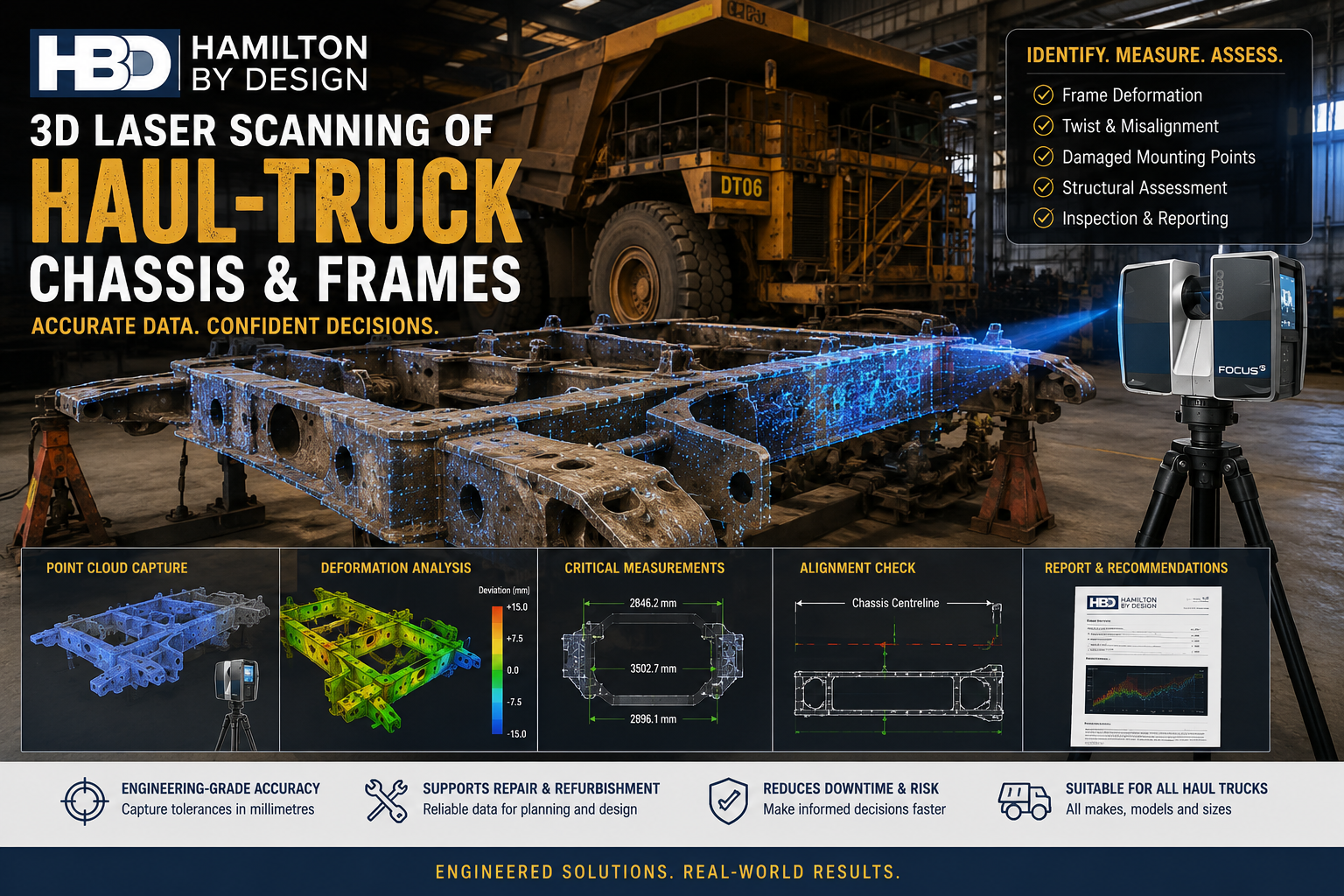
3D Laser Scanning of Haul-Truck Chassis and Frames
Haul-truck chassis and frames operate under severe loading conditions across mining and bulk-material-handling environments. Repeated loading, uneven haul roads, collisions, fatigue, component failures and previous repairs can contribute to localised distortion, damaged mounting points and broader structural misalignment.
Hamilton By Design provides engineer-led 3D laser scanning of haul-truck chassis and frames to capture the existing geometry of the truck structure. The resulting point-cloud data can support dimensional assessment, repair planning, component replacement, refurbishment projects and further engineering investigation.
Unlike isolated tape, level or straight-edge measurements, 3D laser scanning records millions of measurable points across the accessible truck structure. This creates a detailed digital record that can be reviewed from multiple directions and compared against reference geometry, design information or previous scans.
Quantify Haul-Truck Frame Deformation
Chassis distortion can be difficult to confirm using manual measurements alone.
A truck may show visible signs of damage while the full extent of the deformation remains unclear. In other cases, maintenance teams may suspect frame movement because components no longer align correctly, mounting holes do not match, or assemblies are difficult to reinstall.
Three-dimensional scanning can help assess:
- chassis rail straightness;
- frame twist and racking;
- cross-member alignment;
- localised deformation;
- damaged or displaced mounting points;
- deck and platform alignment;
- suspension mounting geometry;
- body or tray mounting locations;
- engine, transmission and equipment mounts;
- repaired structural areas;
- differences between the left- and right-hand sides of the truck; and
- changes between current and historical scan data.
The scan provides a measurable existing-condition record rather than relying solely on visual observations or a limited number of manually selected dimensions.
Why Scan a Mining Truck Chassis?
A haul-truck frame is a large and complex structure. Access restrictions, uneven surfaces and the number of interconnected components can make conventional dimensional inspection time-consuming.
Manual measurements remain valuable for critical checks, but they may not provide enough information to understand the overall geometry of the chassis.
A haul-truck chassis scan can capture the wider structural relationship between frame rails, brackets, cross-members, mounting points and attached equipment.
The information may assist maintenance and engineering teams when investigating:
- abnormal tyre wear;
- uneven suspension behaviour;
- recurring component misalignment;
- damaged body or tray mounts;
- cracking near brackets or cross-members;
- poor component fit-up;
- difficulties installing replacement assemblies;
- accident or impact damage;
- suspected frame twist;
- previous structural repairs;
- structural modification requirements; or
- refurbishment and life-extension decisions.
Engineer-Led 3D Laser Scanning
Hamilton By Design combines terrestrial 3D laser scanning with mechanical engineering, reverse engineering and industrial drafting experience.
The purpose is not simply to produce a point cloud. The scanning scope is developed around the engineering question being investigated.
Before scanning, we seek to understand:
- what issue has been observed;
- where damage or misalignment is suspected;
- which mounting locations are critical;
- whether design drawings or CAD models are available;
- whether the truck can be positioned on a level or controlled surface;
- what components will remain installed;
- which areas must be exposed for scanning; and
- what information is required for repair, design or investigation.
This helps establish an appropriate scanning envelope, scan density and deliverable format.
Typical Haul-Truck Chassis Scanning Process
1. Scope and Investigation Planning
The project begins by identifying the truck model, the suspected problem and the required outcome.
Relevant drawings, repair records, photographs, incident details and previous survey information can be reviewed where available.
The scan plan is then developed around the required structural areas and critical interfaces.
2. Site Preparation
For the clearest possible capture, accessible chassis areas should be cleaned of excessive mud, coal, iron ore, grease and loose material.
Depending on the investigation, removable guards, covers or components may need to be taken away before scanning.
The truck should be isolated and positioned in accordance with the mine site’s safety and maintenance procedures.
Where geometry is being assessed against level or alignment references, the condition and position of the truck should also be documented.
3. Three-Dimensional Data Capture
Multiple terrestrial laser-scanner positions are established around and beneath the accessible areas of the truck.
These scan positions are registered together to create a coordinated three-dimensional point cloud.
Additional manual verification may be completed for selected critical dimensions where practical.
4. Point-Cloud Processing
The captured scans are processed and registered to form a measurable digital representation of the haul-truck chassis and frame.
The point cloud may then be cleaned, segmented and aligned to a project-specific coordinate system.
5. Geometry Assessment
Depending on the agreed scope, the processed data may be used to review:
- centreline alignment;
- chassis rail position;
- frame twist;
- cross-member locations;
- bracket positions;
- mounting-hole centres;
- equipment interface points;
- relative elevations;
- left-to-right symmetry;
- local deformation; and
- clearance between structural and mechanical components.
6. Reporting and Engineering Deliverables
The final deliverables are selected according to the maintenance or engineering objective.
These may include point-cloud files, dimensional drawings, comparison images, deviation maps, sections, CAD geometry or an engineering findings report.
Comparison Against Design Geometry
Where reliable original-equipment-manufacturer drawings or three-dimensional CAD models are available, the scan data may be compared against the intended geometry.
This can help identify areas where the existing frame differs from the nominal design.
Potential comparisons include:
- chassis rail position;
- mounting-point locations;
- cross-member spacing;
- bracket alignment;
- centreline deviation;
- relative height differences;
- localised structural displacement; and
- component interface alignment.
The quality of the comparison depends on the accuracy and revision status of the reference information supplied.
Older drawings, repaired equipment and undocumented modifications should be considered when interpreting any scan-to-design comparison.
Comparison Against a Baseline Scan
Where no reliable design model exists, a baseline scan may still provide significant value.
The truck can be scanned after refurbishment, repair or confirmation of acceptable condition. Future scans can then be compared against the baseline dataset.
Repeat scanning may assist with:
- monitoring known deformation;
- assessing whether movement is continuing;
- reviewing the effectiveness of repairs;
- documenting structural condition over time;
- investigating recurring alignment problems; and
- supporting planned maintenance decisions.
For meaningful repeat comparisons, the truck position, loading condition, suspension condition and scanning methodology should be documented and controlled as far as reasonably practical.
Mounting-Point and Interface Assessment
Damaged or displaced mounting points can create problems well beyond the immediate frame area.
A relatively small movement may affect the alignment of:
- body or tray pivots;
- hoist-cylinder mounts;
- suspension components;
- engine and transmission mounts;
- cooling assemblies;
- access platforms;
- guards;
- hydraulic equipment;
- fuel tanks; or
- replacement structural modules.
Three-dimensional scanning captures the relationship between multiple mounting points rather than treating each point as a separate measurement.
This can help determine whether the issue relates to a single damaged bracket or broader chassis deformation.
Support for Repair and Refurbishment Planning
Scan information can support the development of repair and refurbishment scopes by giving engineers, fabricators and maintenance teams a clearer understanding of the existing condition.
The data may be used to assist with:
- defining damaged areas;
- developing repair drawings;
- designing replacement brackets;
- checking replacement-component fit-up;
- planning temporary supports;
- confirming existing clearances;
- preparing workshop fabrication information;
- assessing alignment before reassembly; and
- recording the completed repair.
The scan does not replace structural engineering judgement, material testing, crack inspection or non-destructive testing.
Instead, it provides dimensional evidence that can be used alongside those investigation methods.
Incident and Failure Investigations
Following an impact, component failure or abnormal operating event, 3D scanning can create a time-stamped geometric record of the haul truck’s condition.
This information may assist an engineering investigation or ICAM-style investigation by helping establish observable facts.
The scan may document:
- displaced structural members;
- damaged brackets;
- relative component positions;
- impact-related deformation;
- altered clearances;
- equipment alignment;
- areas of contact; and
- the geometry before repairs commence.
The resulting data can be reviewed after the truck has been moved, disassembled or repaired, subject to the limitations of the captured scanning envelope.
Haul-Truck Types and Manufacturers
The scanning methodology can be adapted to different haul-truck sizes, configurations and manufacturers.
Applications may include trucks manufactured by:
- Caterpillar;
- Komatsu;
- Liebherr;
- Hitachi;
- Volvo;
- BelAZ; and
- other mining and off-highway equipment manufacturers.
The exact scope will depend on the truck arrangement, site access, exposed structural areas and the engineering issue being investigated.
Typical Deliverables
Depending on the project requirements, deliverables may include:
- registered point-cloud data;
- E57, RCP, RCS, LAS or other agreed scan formats;
- AutoCAD DWG or DXF drawings;
- sectional views through the chassis;
- mounting-point coordinate schedules;
- centreline and alignment information;
- deviation or comparison maps;
- scan-to-CAD overlays;
- SolidWorks, Inventor, STEP, SAT or Parasolid geometry;
- repair-design reference models;
- annotated inspection images; and
- an engineering findings or dimensional-assessment report.
The deliverable should be agreed before site work begins so that the scan density and capture locations suit the intended use.
Important Measurement Considerations
A haul-truck chassis is influenced by its support and loading condition.
Suspension position, tyre pressure, ground level, component loading, tray position and the presence of installed equipment may affect the measured geometry.
For this reason, scan results should be interpreted in the context of:
- how the truck was supported;
- whether the truck was loaded or unloaded;
- the condition of the suspension;
- the levelness of the inspection area;
- which components were installed;
- accessibility and line of sight;
- the condition of the reference drawings; and
- the required measurement tolerance.
Hamilton By Design can assist with developing a practical scanning methodology around the available site and maintenance conditions.
Benefits of Haul-Truck Structural Scanning
Three-dimensional scanning provides several practical advantages:
- broad geometric capture;
- reduced reliance on isolated manual dimensions;
- measurable evidence of frame condition;
- improved communication between site and off-site engineers;
- support for repair and refurbishment planning;
- digital records for future comparison;
- reduced need to repeatedly access the truck;
- improved understanding of mounting relationships;
- support for reverse engineering; and
- clearer information for maintenance decisions.
Australia-Wide Mining Support
Hamilton By Design provides 3D laser scanning, mechanical engineering and reverse-engineering services for mining operations across Australia.
Project support may be available in:
- the Hunter Valley;
- Central Queensland;
- the Bowen Basin;
- the Pilbara;
- Kalgoorlie and the Goldfields;
- Perth;
- Mount Isa;
- Darwin;
- Adelaide;
- Melbourne;
- Sydney;
- regional New South Wales; and
- other Australian mining locations.
Site mobilisation, inductions, access requirements and travel arrangements can be addressed during project planning.
Arrange a Haul-Truck Chassis Scan
Where chassis distortion, damaged mounting points or structural misalignment is suspected, a three-dimensional scan can provide a detailed geometric record of the existing truck condition.
Hamilton By Design can review photographs, drawings, repair information and the suspected issue before proposing an appropriate scanning scope.
Contact Hamilton By Design to discuss haul-truck chassis scanning, mining-truck frame inspection, deformation assessment or structural scanning for repair and refurbishment planning.
Contact Hamilton By Design to discuss engineering-grade 3D laser scanning for your mining haul trucks.

Contact Us – Talk To Us
Our clients:
























