


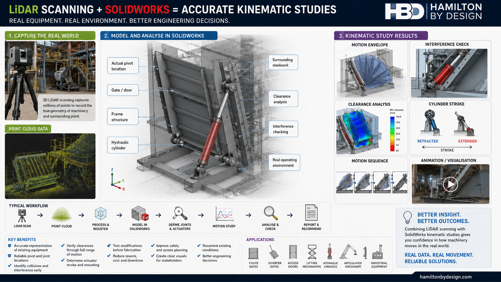
Combining LiDAR Scanning and SolidWorks for Kinematic Studies
Understanding how machinery moves within an existing industrial environment can be difficult when drawings are unavailable, outdated or do not reflect site modifications.
By combining 3D LiDAR scanning with SolidWorks, engineers can create kinematic studies based on the actual installed geometry of machinery, structures and surrounding plant. This provides a more reliable foundation for assessing movement, clearances, interference risks and proposed mechanical modifications.
What Is a Kinematic Study?
A kinematic study examines the movement of mechanical components without initially focusing on the forces that create that movement.
It may assess:
- component position;
- direction of movement;
- travel distance;
- angular rotation;
- velocity;
- acceleration;
- linkage behaviour;
- actuator stroke;
- motion envelopes;
- clearances between components;
- potential collisions or interference.
Kinematic studies are commonly used for mechanical linkages, hydraulic cylinders, access doors, gates, chutes, diverters, lifting systems, articulated equipment and other moving machinery.
Why Existing Geometry Matters
A motion study is only as reliable as the geometry used to create it.
Many industrial machines have been modified, repaired or repositioned over time. Original drawings may no longer represent the actual equipment. Manual measurements may also be difficult where machinery is large, complex, elevated or surrounded by operating plant.
LiDAR scanning provides a detailed three-dimensional record of the equipment and its surroundings. The resulting point cloud can be used as a reference for developing an accurate SolidWorks model.
How LiDAR Scanning Supports the Study
A terrestrial LiDAR scanner records millions of measurement points across the visible surfaces of machinery, structures and plant.
The scan can help establish:
- shaft and pivot locations;
- hinge centres;
- actuator mounting positions;
- linkage lengths;
- equipment orientation;
- machine-frame geometry;
- surrounding structural steel;
- guards and access platforms;
- nearby pipework;
- operating clearances;
- fixed obstructions.
This reduces reliance on assumptions and provides an engineering record of the existing condition at the time of capture.
How SolidWorks Is Used
Once the LiDAR data has been processed, the point cloud can be used to develop simplified or detailed SolidWorks models of the relevant machinery.
SolidWorks can then be used to:
- create individual parts and assemblies;
- locate pivots, shafts and mounting points;
- define mechanical mates and joints;
- simulate rotational and linear movement;
- represent hydraulic-cylinder extension;
- evaluate linkage positions;
- calculate displacement, velocity and acceleration;
- check component interference;
- assess minimum clearances;
- determine the swept path of moving equipment;
- test proposed modifications before fabrication.
The surrounding plant can also be included as reference geometry so the machinery is analysed within its actual operating environment.
Typical LiDAR-to-SolidWorks Workflow
A typical workflow may include:
- Capture the machinery and surrounding plant using a LiDAR scanner.
- Register and process the scan data into a coordinated point cloud.
- Import or reference the point cloud within the CAD workflow.
- Identify the equipment required for the kinematic study.
- Create simplified SolidWorks models of the moving components.
- Position the models using the scanned geometry.
- Define mates, joints, travel limits and actuator movement.
- Run the SolidWorks motion study.
- Review clearances, collisions and movement envelopes.
- Develop recommendations, modifications or fabrication drawings.
Example: Hydraulic Chute Gate
A hydraulic chute gate may include a gate plate, pivot shaft, support frame and hydraulic cylinder.
A LiDAR scan can capture:
- the existing chute geometry;
- the gate position;
- the pivot-shaft location;
- upper and lower cylinder mounts;
- surrounding structural steel;
- platforms, guards and walkways;
- nearby services and obstructions.
The geometry can then be recreated in SolidWorks to assess:
- the gate opening angle;
- the required cylinder stroke;
- the relationship between cylinder travel and gate rotation;
- potential dead-centre positions;
- interference with the chute or surrounding steelwork;
- clearances through the full operating cycle;
- whether a proposed replacement cylinder will fit;
- whether revised mounting points will improve movement.
This allows potential problems to be identified before components are manufactured or installed.
Collision and Interference Assessment
One of the main advantages of combining LiDAR with SolidWorks is the ability to assess moving machinery against the real site environment.
A standalone CAD model may show that a mechanism operates correctly. However, it may not reveal that the moving equipment could contact:
- an existing handrail;
- a structural beam;
- electrical cable trays;
- nearby pipework;
- a maintenance platform;
- machine guarding;
- adjacent equipment.
By modelling the mechanism within the scanned environment, these conflicts can be identified before shutdown, fabrication or installation.
Evaluating Hydraulic Cylinders and Actuators
SolidWorks motion studies can assist with assessing actuator geometry, including:
- extended and retracted cylinder lengths;
- required stroke;
- cylinder mounting angles;
- connection-point movement;
- mechanical advantage;
- actuator alignment;
- over-travel;
- end-of-stroke position;
- potential side loading;
- approach to dead-centre conditions.
Where forces and loads must also be evaluated, the kinematic model may be expanded into a dynamic motion or structural assessment using suitable engineering inputs.
Benefits for Brownfield Engineering
LiDAR and SolidWorks are particularly valuable for brownfield projects where machinery must be modified within an existing facility.
The combined workflow can provide:
- improved confidence in existing dimensions;
- reduced dependence on outdated drawings;
- fewer manual site measurements;
- improved identification of site constraints;
- better interference detection;
- more reliable actuator selection;
- improved design coordination;
- reduced fabrication rework;
- better shutdown planning;
- clearer communication with stakeholders;
- visual animations of proposed movement;
- a documented digital record of existing conditions.
Static Scanning and Multiple Equipment Positions
A conventional terrestrial LiDAR scanner generally captures static geometry rather than continuously recording fast mechanical movement.
For this reason, equipment may be scanned in several controlled positions, such as:
- fully closed;
- partially open;
- fully open;
- maintenance position;
- parked position.
These positions can be compared and used to confirm the geometry and range of movement.
Where actual operating speed or time-dependent behaviour is required, LiDAR data may be combined with:
- video footage;
- shaft encoders;
- linear displacement sensors;
- accelerometers;
- control-system data;
- hydraulic pressure records;
- machine operating logs.
From Kinematic Study to Engineering Deliverables
The SolidWorks model developed from the LiDAR data can support more than the motion study itself.
Potential deliverables may include:
- existing-condition 3D models;
- kinematic study reports;
- movement-envelope drawings;
- interference reports;
- clearance assessments;
- actuator-stroke calculations;
- SolidWorks motion animations;
- general arrangement drawings;
- modification concepts;
- fabrication drawings;
- installation planning models;
- shutdown work packs;
- stakeholder presentation images.
Applications
LiDAR-supported kinematic studies may be suitable for:
- chute gates;
- diverter gates;
- conveyor take-up systems;
- hydraulic linkages;
- access doors;
- lifting mechanisms;
- maintenance hatches;
- articulated machinery;
- robotic systems;
- positioning equipment;
- stackers and reclaimers;
- mobile plant attachments;
- mechanical dampers;
- valve-actuation systems;
- machine guarding;
- equipment relocation projects.
A More Reliable Basis for Mechanical Design
Combining LiDAR scanning with SolidWorks allows a kinematic study to be developed around the actual machine and the actual site environment.
LiDAR captures the existing geometry. SolidWorks converts that information into an intelligent mechanical model that can be moved, tested and reviewed.
Together, these tools can help engineers identify movement restrictions, confirm actuator requirements, assess clearances and test proposed modifications before work reaches fabrication or site installation.
LiDAR Scanning and SolidWorks Support
Hamilton By Design provides engineer-led 3D LiDAR scanning, point-cloud processing, SolidWorks modelling and mechanical design support for existing industrial machinery and brownfield facilities.
Our services can assist with:
- existing-condition capture;
- reverse engineering;
- SolidWorks assembly modelling;
- kinematic studies;
- motion-envelope assessments;
- interference checking;
- actuator and linkage reviews;
- mechanical modifications;
- fabrication drawings;
- installation planning.
For assistance with a kinematic study, machinery modification or LiDAR-based SolidWorks model, contact Hamilton By Design to discuss the equipment, required movement and project objectives.

Contact Us – Talk To Us
Our clients:
























