Reverse Engineering West Gosford NSW

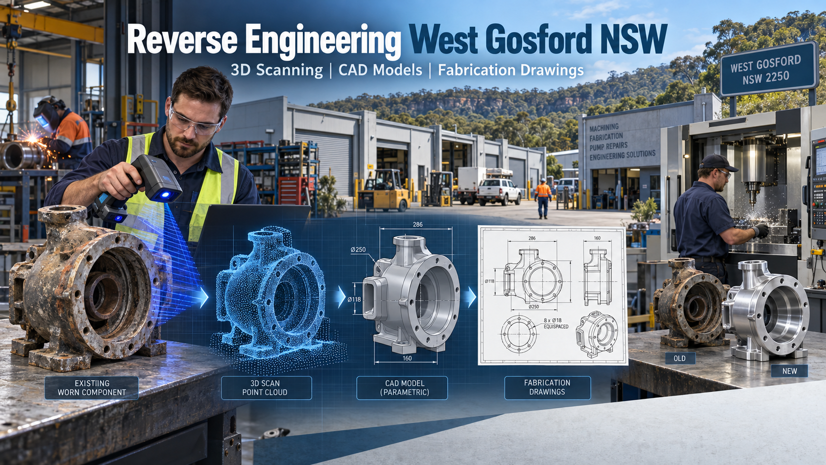
Reverse engineering in West Gosford showing a worn pump component progressing through 3D scanning, CAD modelling and fabrication drawings to a locally manufactured replacement.

Local 3D Scanning, Mechanical Engineering and Manufacturing Support

Blue 3D LiDAR scanner icon on a tripod with scanning waves

West Gosford is one of the Central Coastโ€™s most established industrial precincts. The area supports CNC machining, metal fabrication, pump repairs, vehicle modifications, machinery servicing, electrical manufacturing, industrial supply and other specialist trades.

Many of these businesses work with equipment that has remained in service for years or even decades. Original drawings may have been lost, suppliers may no longer support the equipment, or previous modifications may not have been documented. When a critical component wears out or fails, the only available reference may be the existing physical part.

Hamilton By Design provides reverse engineering in West Gosford for machinery, industrial components and fabricated assemblies. We combine metrology 3D scanning, direct measurement, practical mechanical engineering, 3D CAD modelling and fabrication drawings to help clients recover important engineering information.

Our Central Coast head office is located at Wyong, and we provide mobile site services throughout West Gosford, Gosford, North Gosford, Point Clare, Kariong, Somersby, Lisarow, Tuggerah and surrounding areas.

The objective is not simply to copy a worn component. It is to understand what the component does, identify its important interfaces and produce useful engineering information for local manufacturing.


Supporting Local Manufacturing in West Gosford

West Gosford has a valuable network of machine shops, fabricators, repair workshops and industrial service businesses. These local businesses often have the equipment and practical skills required to machine, weld, cut, fold, repair and assemble replacement components.

However, even an experienced workshop needs reliable information before manufacture begins.

Hamilton By Design can provide the link between the existing physical component and the local manufacturer. We inspect and capture the component, reconstruct it as a controlled CAD model and prepare the drawings or digital files required for production.

Our services can support:

  • CNC machine shops
  • Metal fabricators
  • Pump and rotating-equipment repairers
  • Machinery-maintenance companies
  • Vehicle and trailer manufacturers
  • Marine and generator specialists
  • Production facilities
  • Industrial electrical manufacturers
  • Maintenance contractors
  • Equipment owners
  • Councils and infrastructure operators
  • Manufacturers operating legacy machinery

We can work directly for the equipment owner or collaborate with the clientโ€™s preferred West Gosford or Central Coast workshop.

This approach supports local manufacturing by giving fabricators and machinists clearer information before material is ordered or machining begins.


What Is Reverse Engineering?

Reverse engineering is the process of examining an existing component or machine and recreating the design information needed to understand, reproduce or improve it.

The process may be required when:

  • Original drawings are unavailable
  • The manufacturer no longer supplies the part
  • A replacement component has a long delivery time
  • The equipment has been modified
  • Existing drawings do not match the machinery
  • A worn component must be reconstructed
  • A local workshop needs manufacturing information
  • A spare part is required before the original fails
  • A component needs to be redesigned
  • An existing asset must be documented for future maintenance

Reverse engineering may begin with a physical component, but the final deliverable is usually a controlled engineering record. This could include a 3D CAD model, a machining drawing, a fabrication drawing, an inspection report or a complete assembly model.

Hamilton By Designโ€™s reverse engineering and 3D scanning service combines measurement technology with engineering and manufacturing knowledge.


Metrology 3D Scanning and Direct Measurement

Different components require different measurement methods.

Hamilton By Design can use portable metrology 3D scanning for suitable machinery components and complex surfaces. Larger machines, workshop environments and surrounding plant can be captured using terrestrial LiDAR scanning.

Direct measurement may also include:

  • Vernier calipers
  • Micrometers
  • Bore gauges
  • Tape measurements
  • Angle measurements
  • Bolt-pattern checks
  • Shaft and hole measurements
  • Flange and mounting-face verification

A scanner should not automatically replace conventional measurement. Critical diameters, bearing fits, sealing surfaces and machined interfaces may still require direct checking.

Metrology 3D scanning is particularly useful for:

  • Cast components
  • Irregular shapes
  • Curved surfaces
  • Covers and guards
  • Pump components
  • Worn machinery parts
  • Fabricated assemblies
  • Vehicle components
  • Patterns and moulds
  • Parts with limited drawings

The scan creates a detailed digital representation of the visible surface. This information can then be used as a reference when developing the CAD model.

For larger equipment and surrounding environments, Hamilton By Design also provides 3D scanning services across the Central Coast.


From Scan Data to a 3D CAD Model

A scan mesh or point cloud is not automatically a manufacturing model.

Raw scan data may contain surface texture, wear, damage, corrosion, dirt and small variations that should not be reproduced in the finished part. Engineering interpretation is needed to distinguish useful design geometry from the condition of the component as found.

The development of 3D CAD models may require consideration of:

  • Symmetry
  • Original design intent
  • Bearing and shaft centres
  • Bolt circles
  • Sealing faces
  • Machined surfaces
  • Wall thicknesses
  • Clearances
  • Manufacturing methods
  • Assembly sequence
  • Mating components
  • Maintenance requirements

Hamilton By Design develops CAD models using SolidWorks and other appropriate engineering systems. The model can be constructed with controlled features and nominal dimensions rather than being treated as an uncontrolled surface copy.

This provides a more useful basis for future modifications, manufacturing drawings and engineering review.

Our 3D CAD modelling and mechanical drafting services can convert sketches, measurements, scans and legacy drawings into organised engineering models.


Reverse Engineering Worn Components

One of the greatest risks in reverse engineering is copying wear or damage.

A used component may no longer represent its original geometry. It may have experienced:

  • Abrasive wear
  • Corrosion
  • Impact damage
  • Distortion
  • Fatigue cracking
  • Previous welding repairs
  • Repeated machining
  • Heat damage
  • Misalignment
  • Uneven loading

If the part is scanned and copied without interpretation, the replacement may reproduce the same defect.

A worn shaft may no longer indicate its original bearing fit. A pump casing may have lost material. A fabricated bracket may have bent under load. A previously repaired hole may no longer be in its intended position.

Hamilton By Design reviews the componentโ€™s function, interfaces and condition before finalising the replacement geometry. Where possible, information is gathered from mating parts, maintenance records, old drawings, photographs, catalogues and operating personnel.

Some components may also require material testing, hardness testing, non-destructive examination or specialist analysis. A scan can establish visible geometry, but it cannot identify material grade, heat treatment or internal condition.


Fabrication Drawings for Local Workshops

Once the design has been reconstructed and reviewed, the 3D model can be converted into practical fabrication drawings or machining information.

Depending on the project, deliverables may include:

  • Part drawings
  • Assembly drawings
  • General arrangement drawings
  • Machining drawings
  • Welded fabrication drawings
  • Plate-development drawings
  • DXF cutting profiles
  • STEP files
  • Parasolid files
  • Bills of materials
  • Cutting lists
  • Inspection dimensions
  • Material notes
  • Weld symbols
  • Surface-finish requirements
  • Revision-controlled drawing packages

The required level of detail should be agreed before work begins. A simple laser-cut plate does not require the same documentation as a shaft, pump component or safety-critical machinery assembly.

Hamilton By Design can communicate with the nominated manufacturer during the drawing process. This allows the design to consider available machines, preferred materials and practical workshop methods.

Our role is to provide information that can be understood and used by the people making the component.


Dimensional Inspection Reports

Reverse engineering can also support dimensional inspection and quality assurance.

A dimensional inspection report can compare selected measurements from an existing or newly manufactured part against the nominated CAD model or drawing.

The report may record:

  • Overall dimensions
  • Hole sizes and positions
  • Bolt-pattern geometry
  • Shaft diameters
  • Flange dimensions
  • Mounting locations
  • Alignment measurements
  • Selected tolerances
  • Deviations from the nominated model
  • Inspection limitations

Dimensional inspection reports can be useful when:

  • Checking whether a manufactured component matches the drawing
  • Comparing a spare part with the installed component
  • Investigating repeated fit-up problems
  • Recording the dimensions of an undocumented part
  • Confirming important interfaces before installation
  • Supporting discussions between the client and manufacturer

The report should clearly state what was measured, how it was measured and what tolerances or acceptance criteria were applied.

Not every feature visible in a scan requires inspection. The priority should be the dimensions that control fit, function, alignment or assembly.


Common West Gosford Engineering Problems

Obsolete machinery parts

A machine may remain productive even though the original manufacturer no longer supports it. Reverse engineering can help create the information required for local manufacture.

Missing drawings

The client may have no drawings or only an old sketch. The existing component can be measured and converted into a controlled digital record.

Drawings that do not match the equipment

Machinery may have been changed without corresponding drawing updates. Scanning the actual equipment reduces reliance on outdated information.

Replacement components that do not fit

A component can be accurately manufactured to an incorrect drawing. Capturing the mating equipment and surrounding interfaces can reduce this risk.

Production downtime

Waiting for an overseas part can extend a shutdown. Where technically and legally appropriate, local reverse engineering and manufacturing may provide another pathway.

Limited maintenance records

Creating CAD models, drawings and inspection data gives the asset owner a more reliable record for future maintenance and replacement.

Uncertain original geometry

Wear, corrosion and previous repairs can make the original shape difficult to establish. Engineering judgement and supporting information are needed before the replacement is defined.


Pump and Rotating-Equipment Applications

West Gosford has a strong history of pump, motor, generator, diesel and machinery-repair services. This makes reverse engineering particularly relevant to rotating and fluid-handling equipment.

Potential applications include:

  • Pump casings
  • Pump covers
  • Baseplates
  • Motor adaptor plates
  • Coupling guards
  • Bearing housings
  • Shaft sleeves
  • Pipe and flange interfaces
  • Equipment mounts
  • Service tools
  • Maintenance fixtures
  • Protective covers

Rotating equipment requires careful assessment. Operating speed, balance, materials, fatigue, alignment, fits and clearances may all influence whether a replacement component is suitable.

Hamilton By Design can connect reverse engineering with our industrial pump rebuild and water-engineering services.

Where specialist balancing, metallurgical testing, pressure assessment or certification is required, the relevant specialist should be included in the project.


A Practical Reverse-Engineering Process

A typical project may follow these stages.

1. Define the problem

We establish what has failed, what information is available and whether the client requires a copy, an improved part or a long-term engineering record.

2. Inspect the component

The component is reviewed for wear, damage, corrosion, repairs and features that may affect measurement.

3. Capture the geometry

The item is measured using the most appropriate combination of 3D scanning and direct measurement.

4. Review the interfaces

Mating components, mounting faces, surrounding equipment and installation clearances are checked where practical.

5. Develop the CAD model

A controlled model is created using the scan data, measurements and available engineering information.

6. Review the design

The client, maintainer and proposed manufacturer can review the model before the drawings are finalised.

7. Prepare manufacturing information

The approved model is converted into the required fabrication drawings, machining drawings or digital manufacturing files.

8. Support manufacture and installation

Hamilton By Design can respond to workshop queries, review approved changes and update the final records.

This process keeps responsibility connected from the initial inspection through to the manufacturing documentation.


Engineering Standards and Responsibilities

Applicable Australian Standards depend on the component, machinery and operating environment.

Standards that may be relevant include:

  • AS 1100 series for technical drawing
  • AS/NZS 4024 series for machinery safety
  • AS 3990 for mechanical equipment steelwork
  • AS/NZS 1554 series for structural welding
  • AS 1657 for fixed platforms, walkways, stairs and ladders
  • AS 4991 for lifting devices
  • AS 4041 for pressure piping
  • AS 1210 for pressure vessels

Standards should be selected according to the actual scope. Reverse engineering an existing part does not automatically establish that the original design complied with current requirements.

The client should also confirm that it has the legal right to reproduce proprietary equipment or components. Intellectual-property and licensing requirements may apply.

Hamilton By Design provides mechanical engineering, 3D scanning and drafting. Where specialist electrical, structural, pressure-equipment or other certification is required, an appropriately qualified practitioner should be engaged.


Why Choose Hamilton By Design?

Hamilton By Design has operated since 2001 and has been based on the Central Coast since 2010.

Our capability combines:

  • Mechanical engineering
  • Trade experience as a fitter and turner
  • CNC machining knowledge
  • Mechanical drafting
  • Metrology 3D scanning
  • Terrestrial LiDAR scanning
  • SolidWorks CAD modelling
  • Fabrication-drawing experience
  • Manufacturing knowledge
  • Industrial maintenance experience
  • Controlled engineering documentation

This combination is particularly useful for reverse engineering. We understand the complete workflow from the physical component through measurement, modelling, drawing, manufacturing and installation.

Unlike a scan-only provider, we can convert captured geometry into engineering models and practical drawings. Unlike a remote drafting provider, we can inspect the component, discuss the problem with the workshop and remain involved as the project develops.


Frequently Asked Questions

Do you provide reverse engineering in West Gosford?

Yes. Hamilton By Design provides mobile inspection, scanning, modelling and drafting services throughout West Gosford and the wider Central Coast.

Can you scan a single machinery component?

Yes, where the component is suitable and there is a defined engineering outcome. Photographs and approximate dimensions help us determine the most appropriate approach.

Can you copy a worn or broken part?

Often, but it should not be copied blindly. Wear, distortion and previous repairs must be considered before defining the replacement geometry.

Can a scan determine the material?

No. A scan records visible geometry. Material grade, hardness and heat treatment must be established from records, testing or an appropriate engineering specification.

Can you prepare fabrication or machining drawings?

Yes. We can prepare manufacturing drawings, general arrangements, assemblies, DXF profiles and suitable 3D CAD files according to the agreed scope.

Can you work with our preferred West Gosford manufacturer?

Yes. We can communicate with the clientโ€™s selected machinist or fabricator to help align the drawings with the proposed manufacturing process.

Can you inspect a newly manufactured part?

Yes. Selected dimensions can be compared with the approved drawing or CAD model and recorded in a dimensional inspection report.

What file formats can you supply?

Typical formats include PDF, DWG, DXF, STEP, Parasolid, native SolidWorks files, E57, RCP, RCS and LAS.

How long does reverse engineering take?

The timeframe depends on the size and complexity of the component, required accuracy, available information and level of engineering assessment.

What information is required for a quotation?

Useful information includes photographs, approximate dimensions, equipment function, known materials, failure history, required deliverables, location and target completion date.


Local Engineering Supporting Local Manufacturing

West Gosford has the workshops, trades and practical manufacturing capability needed to support a wide range of industrial equipment.

Hamilton By Design adds the engineering and digital-information layer required to turn an existing component into a controlled manufacturing package.

We can inspect the part, capture its geometry, develop the 3D CAD model, prepare fabrication drawings and assist with dimensional inspection. We can then work with the clientโ€™s preferred local workshop to help move the project from an existing physical asset to a practical replacement.

Contact Hamilton By Design through our online contact page to discuss reverse engineering, metrology 3D scanning or manufacturing drawings for your West Gosford project.

Hamilton By Design โ€“ local engineering supporting local manufacturing on the Central Coast.


Hamilton By Design logo displayed on a blue tilted rectangle with a grey gradient background

Contact Us – Talk To Us

Name
Would you like us to arrange a phone consultation for you?
Address

Our clients:


Related Hamilton By Design Resources

Gosford-3d-scanning-engineering-services/

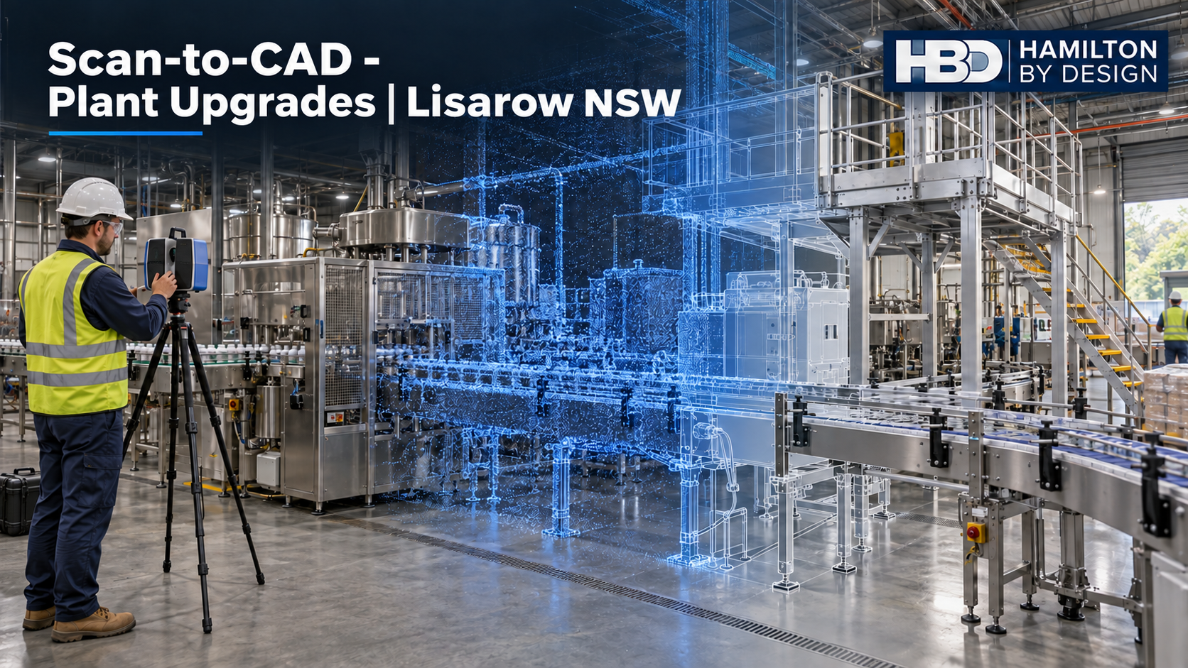
Engineer using a 3D laser scanner for scan-to-CAD plant upgrades in a Lisarow NSW manufacturing facility.
Blue 3D LiDAR scanner icon on a tripod with scanning waves

Lisarow is a compact but diverse industrial location on the NSW Central Coast. Positioned along the Pacific Highway and within practical reach of Gosford, Wyong, Tuggerah, Somersby and the M1 Pacific Motorway, the suburb supports food and beverage production, advanced manufacturing, equipment servicing, warehousing and distribution.

For businesses operating in this environment, engineering projects rarely begin with a clean sheet. Machinery may have been altered over many years, original drawings may no longer reflect the installed plant, and new equipment must often fit around existing conveyors, pipework, structural steel, services and access routes. Production schedules also leave little tolerance for installation errors or repeated site measurement.

Hamilton By Design provides industrial 3D laser scanning, reverse engineering, mechanical design and drafting support for Lisarow manufacturers and the wider Central Coast. Based from its Central Coast head office in Wyong, the company combines site capture with practical engineering and CAD capability. This means the scan is not treated as the final product; it becomes the verified starting point for design, documentation, fabrication and future asset management.

Lisarowโ€™s industrial character

Lisarow contains a notable mixture of production and engineering activity. Publicly documented businesses in the suburb include beverage manufacturing and packaging, locally designed electronic products, frozen-food production, pump overhaul and rotating-equipment services. The area also contains industrial workshops and substantial warehouse facilities supporting distribution throughout the Central Coast and the Sydneyโ€“Newcastle corridor.

These businesses are not identified here as Hamilton By Design clients. They demonstrate the kinds of operations present in Lisarow and the engineering conditions commonly associated with the area.

Food and beverage plants may contain fillers, packaging machines, conveyors, tanks, pipework and wash-down areas. Advanced-manufacturing facilities require controlled component information, production layouts, fixtures and inspection data. Reliability workshops deal with worn components, pumps, shafts, housings and legacy equipment. Warehouses depend on functional loading areas, racking interfaces, materials-handling equipment and safe separation between workers, vehicles and machinery.

These different operations share one fundamental requirement: accurate information about the plant, equipment or component before changes are designed or manufactured.

Engineering-grade 3D laser scanning in Lisarow

Industrial laser scanning uses LiDAR technology to capture millions of measurable points from the surfaces of machinery, buildings, structural steel and services. The resulting point cloud provides a three-dimensional record of the accessible site at the time of capture.

Hamilton By Designโ€™s approach connects reality capture to engineering outcomes. Its broader Central Coast 3D laser scanning and scan-to-CAD service supports brownfield upgrades, equipment replacement, structural modifications and fabrication planning. For projects requiring wider regional coverage, the NSW Central Coast service page explains HBDโ€™s local engineering and scanning capability.

Depending on the agreed scope, scan data may be used to prepare:

  • Registered point clouds
  • Existing-condition plant models
  • Factory and production-line layouts
  • Plans, sections and elevations
  • General arrangement drawings
  • Mechanical and structural interface models
  • Fabrication and manufacturing drawings
  • Installation and modification drawings
  • Clash and clearance reviews
  • Reusable digital records for future projects

Scanning is particularly valuable where manual measurement would be slow, incomplete or disruptive. It can capture the spatial relationship between equipment, columns, conveyors, guards, platforms, pipework and services during a planned visit. Engineers and designers can then return to the point cloud for additional measurements without requiring a new site visit for every design question.

From point cloud to practical CAD information

A point cloud contains substantial geometric information, but it does not automatically become a fabrication drawing or engineered solution. The required objects must be interpreted, modelled and documented to a level suitable for the intended use.

Hamilton By Design provides 3D scanning and CAD modelling services that convert selected scan geometry into usable engineering information. This may include SolidWorks models, AutoCAD layouts, STEP files, general arrangements and detailed drawings.

The required modelling level should be agreed before work begins. A broad factory layout intended for equipment planning does not require every bolt and small pipe fitting to be modelled. Conversely, a replacement machine component may require close attention to critical interfaces, tolerances, fits, material, wear and function.

Defining the intended use prevents unnecessary modelling while ensuring that important engineering details are not omitted.

Recreating missing machinery drawings

Many established factories continue to operate machinery long after the original drawings, suppliers or spare parts have become unavailable. Other machines have been modified several times, leaving the documentation disconnected from the equipment on the floor.

HBDโ€™s reverse-engineering and scan-to-CAD service can capture existing components and convert the required geometry into controlled CAD information. The workflow may include dimensional capture, identification of functional interfaces, CAD reconstruction and preparation of manufacturing drawings.

Reverse engineering should not simply reproduce every feature of a worn or damaged part. The engineer or designer must consider what the component is intended to do, which dimensions control fit and alignment, what material and manufacturing process are appropriate, and whether the observed geometry reflects wear or an earlier repair.

The article From Existing Component to Fabrication Drawing provides further detail on how scan-derived information can support replacement components and fabrication documentation.

Supporting plant modifications and production-line upgrades

Installing new equipment into an operating factory is a spatial and operational challenge. A concept may appear workable on a two-dimensional drawing but clash with an undocumented service, restrict maintenance access or interfere with product flow when installed.

By modelling proposed works within captured site conditions, HBD can assist with:

  • Machinery replacement and relocation
  • Production-line extensions
  • Conveyor and transfer modifications
  • Platforms, stairs, ladders and walkways
  • Equipment-support frames
  • Guarding and safety barriers
  • Pipework and services coordination
  • Maintenance and removal clearances
  • Shutdown planning and installation sequencing

HBDโ€™s mechanical engineering services on the Central Coast combine local site support with mechanical design and documentation. Where conveyors or product movement are involved, its digital engineering for conveyor and materials-handling systems illustrates how scanning, point clouds and CAD coordination can reduce brownfield design risk.

Although that materials-handling page discusses mining applications, the underlying principles also apply to many factories and warehouses: establish the actual geometry, understand the operating requirements, consider safe access, and verify the proposed arrangement before fabrication.

Reducing shutdown and installation risk

Production downtime can be considerably more expensive than the physical modification itself. Short shutdown windows place pressure on fabricators, installers, maintenance teams and project managers. If a support frame, guard, conveyor section or replacement component does not fit, the result may include site cutting, additional welding, crane delays, extended isolation and lost production.

An engineering-led scanning workflow allows more coordination to occur before the shutdown. Tie-in locations can be reviewed, surrounding obstructions identified and proposed components checked within the captured environment. This does not remove the need for appropriate verification or competent engineering judgement, but it provides a stronger baseline than incomplete legacy drawings or isolated tape measurements.

HBDโ€™s 3D LiDAR scanning support for the Central Coast explains how local mobilisation and design-ready site capture can support plant upgrades and installation planning. Nearby operations can also refer to HBDโ€™s dedicated industrial 3D laser scanning service for Tuggerah.

Mechanical drafting for Lisarow manufacturers

Accurate capture only creates value when the resulting information can be communicated to the people who must approve, manufacture, install and maintain the work.

Hamilton By Designโ€™s engineering drafting services on the Central Coast can support projects with:

  • General arrangement drawings
  • Mechanical detail and assembly drawings
  • Fabrication drawings
  • Manufacturing drawings
  • Equipment and factory layouts
  • Bills of materials and part schedules
  • Installation drawings
  • Revision-controlled drawing packages
  • As-existing and as-built documentation

Drawing packages should identify the status and source of the information. Scanned existing geometry, inaccessible or assumed areas, new design, reference dimensions and dimensions requiring site verification should be clearly distinguished.

Depending on the project, drawing and design work may consider the relevant parts of the AS 1100 technical-drawing series, AS/NZS 4024 for machinery safety, AS 1657 for fixed access, AS 4100 for steel structures, AS/NZS 1554 for structural welding and the AS/NZS 1170 structural-actions series. The applicable standards must be established for the actual equipment, hazards, loads and project scope rather than applied as a generic list.

Machinery safety and risk management

Plant modifications can introduce new hazards even when the production objective is achieved. Changes to equipment position, guarding, access or maintenance procedures may create trapping, crushing, shearing, entanglement or fall risks.

HBD can assist with mechanical aspects of plant safety by documenting existing conditions, identifying design interfaces and developing concepts for guards, barriers, platforms and maintenance access. Risk-management assistance may include plant hazard identification, design risk registers, guarding reviews, access assessments and documentation of residual risks requiring control by the client or another specialist.

Safety work must consider foreseeable operation, cleaning, inspection, adjustment, isolation and maintenance. Electrical interlocks, emergency-stop systems and functional-safety validation should be completed by appropriately qualified electrical or control-system specialists where required.

Retaining a reusable digital plant record

The data created for one project can remain valuable long after the immediate modification is finished. Subject to an agreed scope, ownership, confidentiality and retention period, HBD can retain point clouds, machine models, component measurements, plant layouts, replacement-part CAD, manufacturing drawings and modification histories.

This record can give a Lisarow manufacturer a verified starting point for future maintenance and capital projects. It can also reduce reliance on individual knowledge when experienced personnel leave the organisation.

Data arrangements should define permitted access, file formats, revision status, backup expectations, intellectual-property ownership and the period for which information will be retained.

Why engage Hamilton By Design?

Hamilton By Design combines local Central Coast access with engineering-led measurement and documentation. The company uses a connected workflow that can include FARO scanning systems, FARO SCENE, Autodesk ReCap, AutoCAD, SolidWorks and Navisworks. HBD discusses these capabilities in Why Hamilton By Design Has Invested in the FARO Ecosystem.

The practical advantage is continuity. The same project can progress from site capture to point-cloud processing, mechanical interpretation, CAD development and drawing preparation without treating each stage as an unrelated service.

HBDโ€™s Central Coast head office is in Wyong, supporting site attendance in Lisarow and surrounding locations by appointment. Contact details and enquiry options are available on the Hamilton By Design contact page.

Frequently asked questions

Can Hamilton By Design scan an operating factory in Lisarow?

Scanning can often be performed around normal operations, subject to site safety, access and the required accuracy. Moving machinery, vehicles, people, steam, dust or product can affect data capture. Some areas may therefore require isolation or access during a planned stoppage.

Can HBD recreate a part when no drawing exists?

Yes, where the component can be accessed and the necessary engineering information can be established. HBD can capture the component and prepare a CAD model or manufacturing drawing. Material, tolerances, loading, wear and safety-critical functions may require further investigation before manufacture.

What can be produced from a laser scan?

Deliverables may include registered point clouds, plans, sections, elevations, plant layouts, 3D CAD models, general arrangements, equipment-interface models and fabrication drawings. The precise output depends on how the information will be used.

Does the whole factory need to be modelled?

No. Only the geometry relevant to the project normally needs to be converted into CAD. The surrounding point cloud can remain available as spatial reference information. Agreeing the modelling boundary and required detail helps control cost and delivery time.

Can scanning help with conveyor modifications?

Yes. Scanning can record conveyor frames, transfer points, supports, platforms, guards and nearby services. The captured information can support layout changes, clash reviews, access improvements, support design and fabrication documentation.

Can HBD prepare fabrication and manufacturing drawings?

Yes, where these deliverables are included in the agreed scope and the necessary engineering inputs are available. Drawings can be developed from scan data, CAD models and verified design information.

What information is required for a quotation?

Useful information includes the Lisarow site address, photographs, approximate scan area, type of machinery or facility, intended use of the data, required deliverables, preferred file formats, site-access constraints and required completion date.

How long does scanning and modelling take?

Timeframes depend on site size, access, complexity, accuracy, modelling detail and documentation requirements. A component scan and a full production-line capture require very different levels of effort. HBD can confirm a programme after reviewing the scope.

Does HBD service areas surrounding Lisarow?

Yes. HBD supports projects across the NSW Central Coast, including Wyong, Tuggerah, Ourimbah, Somersby, Gosford and surrounding industrial areas. Broader NSW and interstate project support is also available.

Can the scan and CAD information be retained for future work?

Yes, subject to agreed client permissions, confidentiality, ownership and storage arrangements. Retaining a controlled digital record can make future modifications faster and reduce repeated measurement.

Discuss a Lisarow industrial project

Whether the requirement involves a missing machine drawing, an obsolete component, a conveyor modification, a production-line upgrade or a verified record of existing plant, the first step is to define the intended engineering outcome.

Hamilton By Design can capture the existing conditions, convert the relevant information into practical CAD deliverables and support the mechanical design and documentation required for the next stage of the project.

Contact Hamilton By Design to discuss industrial 3D scanning, reverse engineering or mechanical drafting for a Lisarow or Central Coast facility.


Hamilton By Design logo displayed on a blue tilted rectangle with a grey gradient background

Contact Us – Talk To Us

Name
Would you like us to arrange a phone consultation for you?
Address

Our clients:


Material Handling: Bucket Elevator Scan, Design, Build and Install

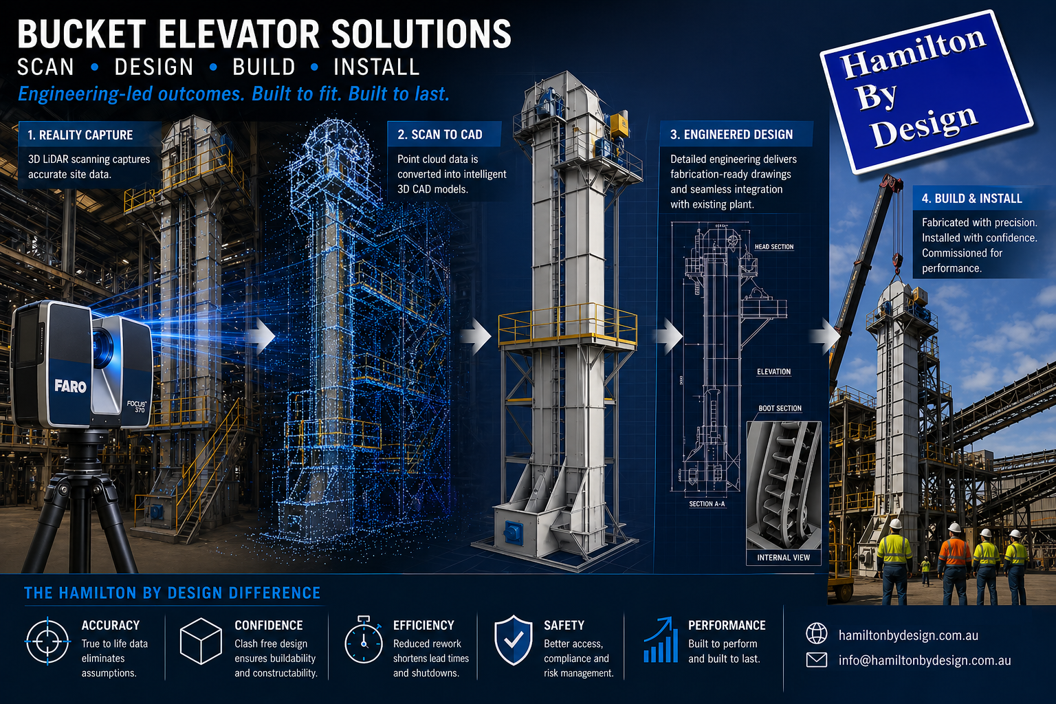
3D LiDAR scanning to CAD modelling workflow for a bucket elevator system in an industrial material handling plant

An Engineering-Led Approach for Brownfield Industrial Environments

Bucket elevators are a fundamental component of bulk material handling systems, providing an efficient and reliable method for the vertical transport of materials such as ores, grains, cement, and industrial powders. Despite their apparent simplicity, the successful design and installation of bucket elevators within existing (brownfield) facilities presents significant engineering challenges. These challenges typically arise from undocumented modifications, limited access, and the inherent complexity of integrating new infrastructure into legacy plant environments.

This paper outlines an engineering-led methodology adopted by Hamilton By Design, incorporating 3D LiDAR scanning, scan-to-CAD modelling, and fabrication-ready design to deliver a complete scan, design, build, and install solution for bucket elevator systems.


3D CAD Modelling Australia service banner for Hamilton By Design

Limitations of Traditional Design Methodologies

Conventional approaches to bucket elevator design often rely on outdated drawings, manual site measurements, and engineering assumptions regarding existing plant conditions. While these methods may be adequate for greenfield developments, they are frequently inadequate in brownfield environments.

Common issues associated with traditional methodologies include:

  • Dimensional inaccuracies leading to misalignment during installation
  • Increased fabrication rework due to unforeseen clashes
  • Extended shutdown durations and associated production losses
  • Elevated safety risks resulting from poor integration with existing infrastructure

In material handling systems, particularly those involving rotating equipment and vertical conveyance, dimensional accuracy is critical. Minor deviations can result in significant operational inefficiencies, including premature wear, belt tracking issues, and mechanical failure.


Engineering-Grade 3D LiDAR Scanning

To address these challenges, an engineering-grade 3D LiDAR scanning process is employed to capture a high-resolution, spatially accurate representation of the existing plant environment. This process generates a point cloud dataset that reflects the true geometry of all visible structures, equipment, and interfaces.

The application of LiDAR scanning provides the following advantages:

  • Accurate capture of structural steelwork, platforms, and existing material handling systems
  • Identification of spatial constraints and potential clashes prior to design development
  • Reliable definition of tie-in points for new equipment
  • Reduction in reliance on assumptions and manual measurement

Importantly, the point cloud dataset is treated as an engineering input, rather than a visual reference. This distinction ensures that all subsequent design activities are grounded in verified, real-world data.


Scan-to-CAD Modelling and Engineering Design

Following data acquisition, the point cloud is processed and converted into a structured, parametric CAD model. This scan-to-CAD workflow enables the development of detailed engineering designs that accurately reflect existing site conditions.

Typical deliverables include:

  • Three-dimensional parametric models suitable for engineering analysis and coordination
  • General Arrangement (GA) drawings illustrating system layout and interfaces
  • Detailed sections and elevations through critical components
  • Interface definitions with existing conveyors, chutes, and structural systems

This approach facilitates seamless integration of the bucket elevator with existing plant infrastructure. Furthermore, it enables multidisciplinary coordination, ensuring alignment between mechanical, structural, and operational requirements.

A key differentiator of this methodology is the focus on producing fabrication-ready outputs, rather than conceptual or visual models. This ensures that the design intent can be directly translated into manufacturable components.


Engineering Considerations in Bucket Elevator Design

The design of a bucket elevator system must address a range of mechanical, structural, and operational factors.

Mechanical Design Parameters

  • Selection of belt or chain systems based on material characteristics and throughput requirements
  • Determination of bucket spacing, capacity, and configuration
  • Design of head pulley assemblies and drive systems
  • Specification of boot sections, including tensioning and clean-out provisions

Structural Integration

  • Design of support frames and load transfer mechanisms
  • Assessment of existing structural capacity and required reinforcements
  • Compliance with relevant standards, including AS 1657 for access and maintenance systems

Operational and Maintenance Considerations

  • Material flow behaviour and potential for blockages
  • Dust containment and environmental controls
  • Provision of safe access for inspection, maintenance, and replacement activities

By integrating scan data with engineering analysis, the resulting design is optimised for both performance and constructability within the constraints of the existing facility.


Fabrication and Quality Assurance

The transition from design to fabrication is significantly enhanced by the availability of accurate, detailed engineering documentation. Fabrication drawings derived from scan-based models provide a high degree of confidence in component fitment and assembly.

Key benefits include:

  • Reduction in fabrication errors and rework
  • Improved efficiency in workshop processes
  • Accurate material take-offs and procurement planning
  • Enhanced quality assurance through alignment with verified design data

Engineering oversight during fabrication ensures that all components meet specified tolerances and performance requirements.


Installation and Commissioning

Installation of bucket elevator systems within operational facilities is typically constrained by limited shutdown windows and restricted access. As such, careful planning and coordination are essential.

An engineering-led installation approach includes:

  • Development of detailed installation methodologies and sequencing
  • Planning of lifting operations and access requirements
  • Verification of alignment and fitment using scan data
  • Provision of on-site engineering support during critical installation phases

The use of pre-validated design data significantly reduces installation risk, minimises delays, and ensures a more efficient commissioning process.


Benefits of an Integrated Scan, Design, Build and Install Approach

The integration of LiDAR scanning, engineering design, and fabrication support provides a number of measurable benefits:

  • Reduced project risk through improved dimensional accuracy
  • Enhanced constructability and reduced fabrication rework
  • Shorter installation durations and reduced plant downtime
  • Improved coordination between engineering, fabrication, and site teams

For project stakeholders, this approach delivers greater certainty in both project outcomes and timelines.


Applications in Industry

This methodology is applicable across a range of industries where bulk material handling systems are utilised, including:

  • Mining and mineral processing operations
  • Agricultural and grain handling facilities
  • Cement and bulk powder processing plants
  • Recycling and industrial manufacturing environments

It is particularly valuable in brownfield projects involving upgrades, retrofits, or replacement of existing bucket elevator systems.


Conclusion

The successful implementation of bucket elevator systems in brownfield environments requires a departure from traditional design methodologies. By adopting an engineering-led approach grounded in accurate spatial data, it is possible to significantly reduce project risk and improve overall outcomes.

Hamilton By Design provides a comprehensive solution that integrates 3D LiDAR scanning, scan-to-CAD modelling, and fabrication-ready design. This approach ensures that bucket elevator systems are not only theoretically sound but also practically deliverable within the constraints of real-world industrial environments.

3D LiDAR scanning and 3D modelling service button โ€” laser scanner capturing a point cloud for engineering and CAD modelling
Mechanical engineering services

Contact Us – Talk to Us


Hamilton By Design logo displayed on a blue tilted rectangle with a grey gradient background

E-Mail: [email protected]

3D CAD Modelling Australia service banner for Hamilton By Design
Australian Drafting logo featuring bold white text reading "Australian Drafting" centred on a blue rounded rectangle background.
Engineering Governance title graphic featuring bold white text reading "Engineering Governance" centred on a blue rounded rectangle background.
Mechanical, Structural & Pipework Drafting service banner by Hamilton By Design featuring white text on a blue background.
Mechanical engineering services
Blue rounded button with the text โ€œSolidWorks Designโ€ in white.
Finite Element Analysis (FEA) engineering simulation button
3D LiDAR Scanning Darwin for engineering surveys, laser scanning, reality capture and point cloud modelling services
3D LiDAR Scanning Australia engineering services for laser scanning, reality capture, scan-to-CAD, Scan-to-BIM and as-built documentation across Australia
3D LiDAR scanning services on the Central Coast providing engineering-grade laser scanning, point cloud capture, scan-to-CAD modelling and industrial reality capture for infrastructure and industrial projects.
3D LiDAR Scanning Perth for engineering surveys, laser scanning, reality capture and point cloud modelling services
3D LiDAR Scanning Sydney for engineering surveys, laser scanning, reality capture and point cloud modelling services
3D LiDAR Scanning Brisbane for engineering surveys, laser scanning, reality capture and point cloud modelling services
3D LiDAR Scanning Canberra for engineering surveys, laser scanning, reality capture and point cloud modelling services
3D LiDAR Scanning Newcastle for engineering surveys, laser scanning, reality capture and point cloud modelling services
3D LiDAR Scanning Adelaide for engineering surveys, laser scanning, reality capture and point cloud modelling services

Wearable 3D Scanners vs Engineering-Grade LiDAR

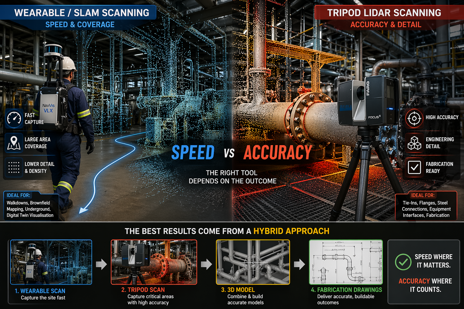
Wearable SLAM lidar scanner compared with tripod laser scanner in an industrial plant showing speed versus accuracy in point cloud data

Wearable 3D Scanners vs LiDAR | Engineering Accuracy Explained

Why Speed Doesnโ€™t Always Mean Accuracy in Industrial Scanning

Blue 3D LiDAR scanner icon on a tripod with scanning waves

Wearable 3D scanning systems โ€” often referred to as backpack or body-mounted LiDAR scanners โ€” are becoming increasingly common across mining, construction, and industrial environments.

These systems allow an operator to walk through a site and capture data in real time, significantly reducing time spent in the field.

However, while speed has improved, an important question remains:

Are wearable scanners suitable for engineering and fabrication work?

At Hamilton By Design, we take an engineering-led approach to scanning. The answer is not as simple as many vendors suggest.


3D LiDAR scanning and 3D modelling service button โ€” laser scanner capturing a point cloud for engineering and CAD modelling
Mechanical engineering services

What Are Wearable 3D Scanners?

Wearable scanners, also known as SLAM LiDAR systems, are designed to be worn while walking through a site.

They typically use a combination of:

  • LiDAR sensors
  • Cameras
  • Inertial Measurement Units (IMU)
  • SLAM (Simultaneous Localisation and Mapping) algorithms

This allows the system to generate a continuous 3D point cloud without the need for tripod setups or survey targets.

In simple terms, the operator becomes the scanner.


The Key Advantage: Speed

The main advantage of wearable systems is speed.

They allow for:

  • Rapid site capture
  • Minimal setup time
  • Scanning of complex or confined environments
  • Efficient coverage of large areas

For walkdowns, site familiarisation, and early-stage layouts, wearable scanning is highly effective.


The Trade-Off: Accuracy and Detail

While wearable systems offer speed, they come with trade-offs.

Wearable SLAM scanners typically produce:

  • Lower point density
  • Reduced edge definition
  • Positional drift over longer distances

In contrast, traditional terrestrial LiDAR scanners provide:

  • High-density point clouds
  • Sharp and well-defined geometry
  • Millimetre-level accuracy
  • Repeatable and verifiable results

Why This Matters for Engineering

In industrial environments, scan data is not just for visualisation. It is used for:

  • Design modelling
  • Clash detection
  • Fabrication drawings
  • Installation planning

If the data lacks accuracy, it can lead to:

  • Misaligned pipework
  • Incorrect steel fabrication
  • Costly rework during shutdowns

A model that looks correct is not the same as a model that is correct.


Where Wearable Scanning Works Best

Wearable systems are well suited to:

  • Large-scale site capture
  • Underground environments
  • Brownfield walkdowns
  • Asset mapping
  • Digital twin visualisation

They provide excellent coverage and speed, but are not always suitable for detailed engineering work.


Where Engineering-Grade LiDAR Is Essential

Tripod-based LiDAR scanning is critical for:

  • Tie-in points
  • Flanges and pipe interfaces
  • Structural steel connections
  • Equipment interfaces
  • Fabrication-ready modelling

These are areas where millimetre-level accuracy is required.


The Reality: A Hybrid Approach

The most effective approach is not choosing one system over the other, but combining both.

A typical workflow includes:

  • Wearable scanning to capture the full site quickly
  • Tripod LiDAR scanning to capture critical areas with high accuracy

This provides both speed and precision.


Engineering-Led Scanning vs Fast Scanning

There is a common misconception that faster scanning leads to better outcomes.

In reality:

  • Fast data is only useful if it is accurate
  • Point clouds must support engineering decisions
  • Accuracy must align with project risk

At Hamilton By Design, the focus is on delivering:

  • Engineering-grade outputs
  • Scan-to-model workflows
  • Fabrication-ready data

Our clients

3D CAD Modelling Australia service banner for Hamilton By Design

Talk to us – Contact Us

Name
Would you like us to arrange a phone consultation for you?
Address

Inspired By Jim


3D CAD Modelling Australia service banner for Hamilton By Design
Australian Drafting logo featuring bold white text reading "Australian Drafting" centred on a blue rounded rectangle background.
Engineering Governance title graphic featuring bold white text reading "Engineering Governance" centred on a blue rounded rectangle background.
Mechanical, Structural & Pipework Drafting service banner by Hamilton By Design featuring white text on a blue background.
Mechanical engineering services
Blue rounded button with the text โ€œSolidWorks Designโ€ in white.
Finite Element Analysis (FEA) engineering simulation button
3D LiDAR Scanning Darwin for engineering surveys, laser scanning, reality capture and point cloud modelling services
3D LiDAR Scanning Australia engineering services for laser scanning, reality capture, scan-to-CAD, Scan-to-BIM and as-built documentation across Australia
3D LiDAR scanning services on the Central Coast providing engineering-grade laser scanning, point cloud capture, scan-to-CAD modelling and industrial reality capture for infrastructure and industrial projects.
3D LiDAR Scanning Perth for engineering surveys, laser scanning, reality capture and point cloud modelling services
3D LiDAR Scanning Sydney for engineering surveys, laser scanning, reality capture and point cloud modelling services
3D LiDAR Scanning Brisbane for engineering surveys, laser scanning, reality capture and point cloud modelling services
3D LiDAR Scanning Canberra for engineering surveys, laser scanning, reality capture and point cloud modelling services
3D LiDAR Scanning Newcastle for engineering surveys, laser scanning, reality capture and point cloud modelling services
3D LiDAR Scanning Adelaide for engineering surveys, laser scanning, reality capture and point cloud modelling services

Why Point Cloud Data Beats STL for Real Engineering Work

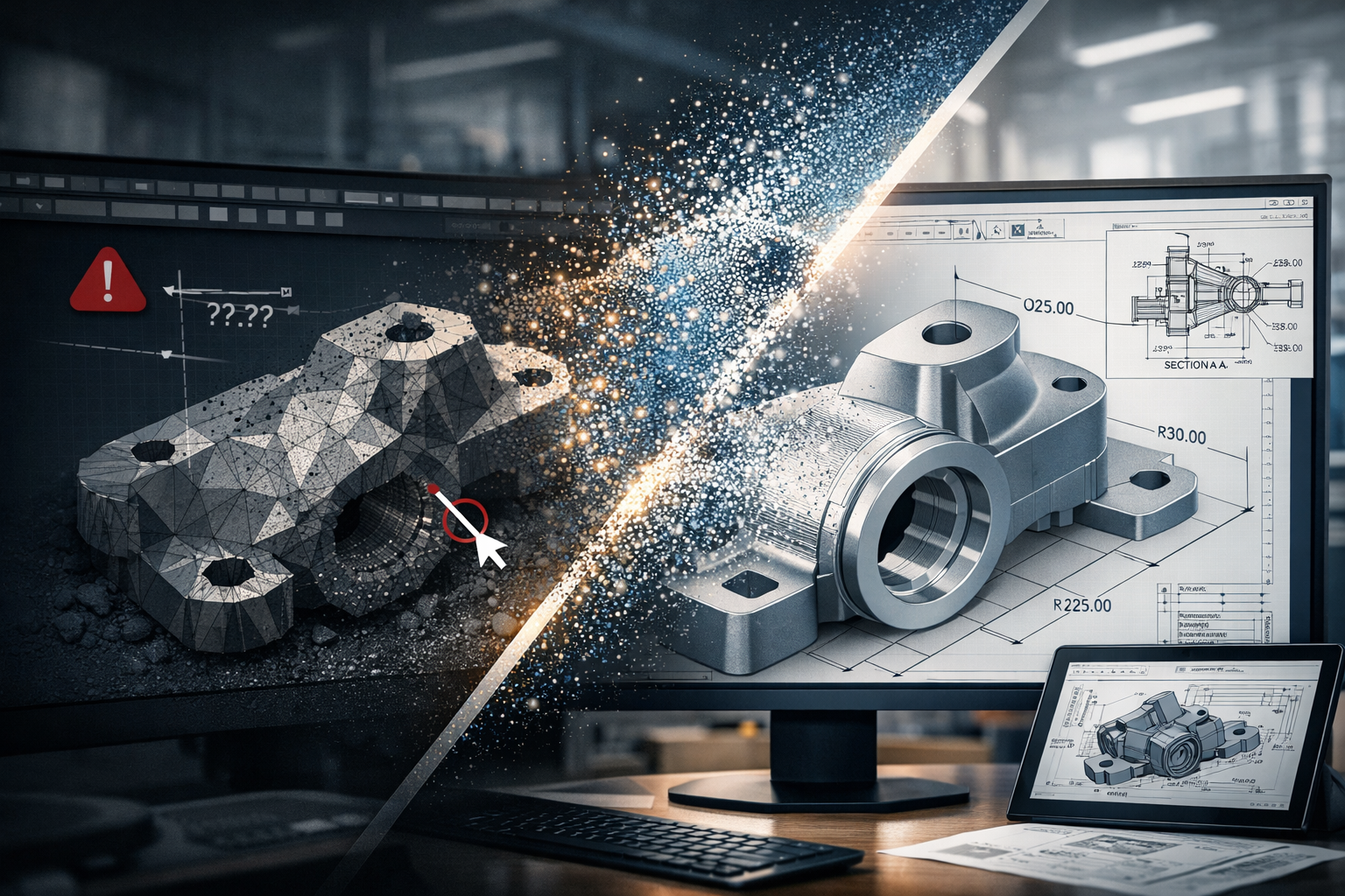
Point cloud to CAD workflow showing transition from STL mesh to engineering-ready parametric model with dimensions and drawings

In the world of 3D scanning, there is often confusion around what type of data is actually useful for engineering. Many providers offer high-accuracy scanning using metrology-grade equipment, yet the final deliverable is often limited to STL or OBJ files.

The question is simple:
If the data cannot be used inside your CAD system, what is its real value?


The Rise of Metrology-Grade Scanning

Modern handheld scanners are incredibly capable. They can capture fine detail, achieve high accuracy, and generate dense surface representations of components. These systems are often used in reverse engineering, product design, and inspection workflows.

They are frequently marketed as โ€œmetrology-grade,โ€ and in terms of capture capability, that claim is valid. These scanners can measure to very tight tolerances and produce highly detailed digital representations.

However, the real issue is not how the data is captured.
It is how the data is delivered and how it integrates into engineering workflows.

Capturing accurate data is only the first step. The true value lies in whether that data can be used to design, modify, verify, and manufacture real-world components.


STL and OBJ โ€“ A Surface, Not a Solution

STL and OBJ files are mesh-based formats. They represent the surface of an object using thousands or millions of triangles stitched together to form a 3D shape.

These files are useful for:

  • Visualisation
  • 3D printing
  • Basic reference and communication

They are fast to generate and easy to share, which is why many scanning providers stop at this stage.

However, they come with significant limitations:

  • No parametric geometry
  • No selectable engineering features
  • No design intent
  • Difficult to dimension accurately
  • Cannot drive CAD models effectively

A mesh file is essentially a visual representation, not an engineering model.

In simple terms:

An STL file shows what something looks like, but not how to design, modify, or manufacture it.

Once the data is converted into a mesh, it is often smoothed, simplified, and processed. This means the original measured data is no longer fully preserved, and any measurements taken from the mesh are based on an interpreted surface rather than raw coordinates.


Engineering Happens in CAD

Real engineering work takes place inside platforms such as SolidWorks, Autodesk Inventor, Autodesk Fusion, and Onshape.

These tools are built around:

  • Parametric modelling
  • Feature-based design
  • Relationships and constraints
  • Editable geometry

They rely on identifiable features such as:

  • Planes
  • Cylinders
  • Holes
  • Edges and faces

Mesh files do not contain this level of intelligence. As a result, they cannot be easily used to:

  • Modify or optimise designs
  • Perform engineering calculations or simulations
  • Generate fabrication-ready drawings
  • Maintain consistency across revisions

This creates a disconnect:

You can measure on the scanner, but you cannot effectively design in CAD.

And if design cannot happen in CAD, the workflow breaks down.


The Advantage of Point Cloud Data

Point cloud data, typically delivered in formats such as E57 or RCP, captures real-world coordinates directly from the scan. Each point represents a measurable location in 3D space.

This is fundamentally different from a mesh.

Point clouds provide:

  • True measured data (not interpreted surfaces)
  • High-density spatial accuracy
  • Full capture of the environment or component
  • The ability to revisit and re-measure at any time

This enables engineers to:

  • Extract accurate dimensions directly from real-world data
  • Fit geometry (planes, cylinders, centre lines) inside CAD
  • Validate designs against existing conditions
  • Maintain traceability and confidence in the data

Point clouds form the foundation for engineering-grade modelling, not just visual representation.


From Scan to Engineering Outcome

At Hamilton By Design, the focus is not just on capturing data, but on delivering usable engineering outcomes.

Our workflow is:

Scan โ†’ Point Cloud โ†’ CAD Model โ†’ Engineering Drawings

This ensures the data can be:

  • Measured inside CAD
  • Verified and checked against real conditions
  • Modified to suit design requirements
  • Used for fabrication, installation, and real-world implementation

This approach bridges the gap between reality and design.

It turns captured data into something that engineers, fabricators, and project teams can actually use.


Like-for-Like vs Design Flexibility

If your requirement is a like-for-like digital representation of an object, mesh files such as STL or OBJ may be sufficient.

They provide a quick and effective way to visualise shape and form.

However, if your goal is to:

  • Modify a design
  • Integrate with existing infrastructure
  • Produce engineering drawings
  • Support fabrication or installation

Then flexibility becomes critical.

If youโ€™re looking for like-for-like, mesh will get you there.
If youโ€™re looking for a flexible design tool, point cloud is the answer.


The Bottom Line

Metrology-grade scanners can capture extremely accurate data. But if that data is delivered only as an STL or OBJ file, its value is significantly limited within an engineering context.

True value comes from transforming scan data into something that works inside CAD and supports real-world outcomes.

Mesh files deliver a shape.
Point clouds deliver a foundation for engineering.

3D CAD Modelling Australia service banner for Hamilton By Design
Finite Element Analysis (FEA) engineering simulation button
Mechanical engineering services

Mechanical Engineering | Structural Engineering


3D Scanning & Mechanical Engineering Services โ€“ Yorke Peninsula, South Australia

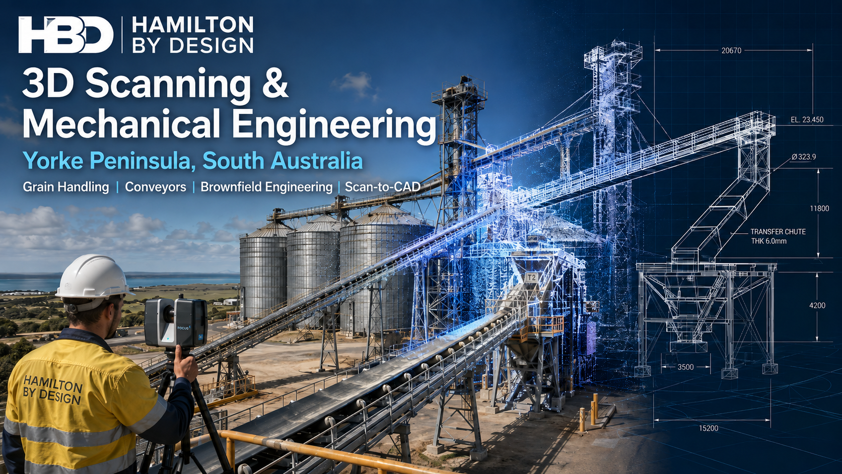
3D scanning and mechanical engineering for Yorke Peninsula grain handling facilities, showing conveyors, silos, FARO laser scanning, point cloud capture and CAD modelling.
Blue 3D LiDAR scanner icon on a tripod with scanning waves

The Yorke Peninsula is an important regional area of South Australia, supporting agriculture, grain handling, bulk storage, transport infrastructure, manufacturing, maintenance activities and a wide range of regional businesses. When existing facilities require modification, replacement equipment, additional structures or improved documentation, one of the biggest challenges is often understanding exactly what is already installed.

Hamilton By Design provides 3D scanning, mechanical engineering, CAD modelling and drafting services across the Yorke Peninsula and regional South Australia, helping project teams capture existing conditions and convert that information into practical engineering deliverables.

Our approach combines site-based reality capture with engineering and design. Rather than treating scanning as an isolated surveying activity, the captured information can become the starting point for plant modifications, equipment replacement, fabrication, structural detailing, reverse engineering and brownfield project development.

For projects requiring accurate existing-condition information, our broader 3D LiDAR scanning services in Adelaide and South Australia support industrial, infrastructure, manufacturing and regional engineering projects throughout the state.


3D LiDAR scanning and 3D modelling service button โ€” laser scanner capturing a point cloud for engineering and CAD modelling
Mechanical engineering services

Engineering Support for Existing Yorke Peninsula Facilities

Regional facilities often develop progressively over many years. Equipment may have been replaced, conveyors extended, platforms modified, pipework rerouted or structural steel added without every change being accurately reflected in the original drawings.

This creates a problem when another modification is required.

A drawing may show what was originally designed, but not necessarily what exists today.

For brownfield engineering projects, Hamilton By Design uses engineering-grade 3D laser scanning to capture existing structures, mechanical equipment, access systems and surrounding infrastructure before detailed design begins.

The resulting point cloud provides a three-dimensional record of the site that can be reviewed and measured after the fieldwork has been completed.

This can reduce the need for repeated site visits and allows designers to work with existing geometry rather than assumptions.

What Can Be Captured Using 3D LiDAR Scanning?

3D scanning can be applied to individual pieces of equipment or large sections of an industrial facility.

Typical Yorke Peninsula applications may include:

  • grain handling equipment
  • conveyors and conveyor galleries
  • transfer stations
  • chutes and hoppers
  • silos and storage structures
  • structural steel
  • platforms, stairs and handrails
  • machinery and equipment
  • pipework and service routes
  • equipment foundations
  • building interiors
  • plant rooms
  • access areas
  • existing fabrication
  • equipment interfaces.

For engineering projects, accurate capture of the surrounding area can be just as important as capturing the equipment being replaced.

Our 3D laser scanning for engineering projects workflow provides engineers and designers with a digital representation of existing plant and structures that can then be used as the basis for engineering development.

This is particularly useful when a new component has to fit between existing structures, connect to established equipment or be installed during a limited shutdown period.

Grain Handling and Bulk Materials Engineering

Grain and bulk-material facilities present their own engineering challenges.

Conveyors, chutes, hoppers, transfer points and supporting structures operate as connected systems. A modification made to one part of the plant can affect material flow, maintenance access, clearances and the performance of equipment further downstream.

Hamilton By Design’s experience with bulk material handling systems can support projects where existing equipment needs to be modified, replaced or integrated with new plant.

While individual industries and materials differ, many of the engineering principles remain similar.

The objective is not simply to produce a CAD model. It is to understand how the equipment fits into the complete operating environment.

3D scanning can help establish:

  • existing conveyor positions
  • belt centre lines
  • chute geometry
  • support locations
  • surrounding structural steel
  • head and tail pulley arrangements
  • maintenance clearances
  • access requirements
  • equipment interfaces
  • available installation space.

Having this information available during design can significantly improve the coordination of modifications.

Conveyor, Chute and Transfer Station Projects

Transfer points can become maintenance-intensive areas when material flow, equipment geometry or operating conditions are not properly considered.

Excessive wear, spillage, dust, blockages and difficult maintenance access can all create operational problems.

Hamilton By Design provides engineering and design support for conveyor transfer chute design, including projects where existing structures and equipment need to be captured before new components can be developed.

For a Yorke Peninsula brownfield project, the process may begin by scanning the conveyor, chute, support structure and surrounding area.

The point cloud can then be imported into the engineering environment, allowing proposed equipment to be positioned relative to the actual plant.

This approach is particularly valuable where site access is difficult or where measuring individual components manually would require numerous dimensions to be recorded.

Scan-to-CAD for Brownfield Engineering

Capturing a point cloud is only the first stage.

The information can then be converted into engineering geometry suitable for design, documentation and coordination.

Depending on the project, Hamilton By Design can develop:

  • 3D CAD models
  • existing-condition models
  • general arrangement drawings
  • sections and elevations
  • mechanical layouts
  • structural layouts
  • fabrication drawings
  • equipment models
  • interface geometry
  • installation concepts.

This allows the physical site to become part of the CAD design environment.

New equipment can be modelled around existing structures, and potential interference can be investigated before fabrication or installation.

For brownfield work, this creates an important connection between site capture and engineering design.

Reverse Engineering Existing Equipment

Regional facilities can contain machinery that has been operating for many years.

In some cases, original manufacturing drawings may no longer be available. Equipment may also have been repaired, modified or altered during its operating life.

When components require replacement, scanning can provide an effective starting point.

Hamilton By Design’s reverse engineering using 3D scanning workflow uses captured geometry together with engineering assessment, CAD modelling and dimensional verification.

Applications may include:

  • replacement components
  • obsolete machinery
  • worn equipment
  • guards and covers
  • fabricated structures
  • chutes and hoppers
  • equipment interfaces
  • legacy plant.

Importantly, reverse engineering does not necessarily mean blindly copying an existing component.

The existing geometry provides information about what fits the plant, while engineering review can consider whether the replacement can be improved for manufacture, installation, maintenance or service life.

Digital Verification and Quality Assurance

3D scanning can also be useful after fabrication or installation.

A scan of installed equipment can be compared with the design model to identify potential differences and confirm important geometry.

Hamilton By Design’s 3D LiDAR digital quality assurance services can assist project teams with dimensional verification and existing-condition documentation.

This may be useful where a project requires confidence that equipment, structures or interfaces have been installed as expected before the next stage of work proceeds.

For regional projects, having a permanent digital record can also reduce uncertainty during future modifications.

Supporting Shutdowns and Plant Upgrades

Shutdown projects often provide only a limited period in which existing equipment can be removed and replacement components installed.

Discovering an unexpected obstruction after fabrication has begun can create significant problems.

Capturing the existing plant before detailed design allows the project team to investigate many potential fit-up issues earlier.

The scanned environment can assist with:

  • checking equipment clearances
  • planning replacement components
  • developing installation concepts
  • identifying surrounding obstructions
  • reviewing access
  • coordinating structural and mechanical work
  • developing fabrication drawings.

This does not remove every risk associated with brownfield work, but it provides significantly more information than relying solely on old drawings and isolated manual dimensions.

Mechanical Engineering and Drafting From the Same Digital Dataset

A major advantage of engineering-led scanning is that the data does not have to stop at the point-cloud stage.

Hamilton By Design can use the captured information as part of a broader engineering workflow incorporating mechanical design, CAD modelling, drafting and fabrication documentation.

Our national 3D laser scanning services support projects where accurate site capture needs to connect directly with subsequent engineering work.

Depending on project requirements, deliverables can include registered point clouds, CAD models, drawings and engineering information suitable for continued project development.

This integrated approach is particularly useful for smaller and regional projects where having multiple companies separately responsible for site measurement, modelling and drafting can create unnecessary handover points.

3D Scanning Across the Yorke Peninsula

Hamilton By Design can support projects across the Yorke Peninsula and surrounding regional areas.

Projects do not necessarily need to involve an entire facility.

A scanning assignment may involve one conveyor transfer, an individual piece of machinery, a structural modification or a small area where accurate measurements are required.

For larger projects, scanning can be expanded to capture an entire working area and provide project teams with a broader existing-condition dataset.

The appropriate scope depends on what the client needs to design, modify, replace or document.

Why Use 3D Scanning Before Starting a Brownfield Design?

The greatest benefit is simple: designing around what actually exists.

Brownfield projects frequently involve compromises imposed by existing structures, equipment, access and operating requirements.

A point cloud provides engineers and designers with significantly more spatial information than a collection of individual measurements.

That can assist project teams in making better-informed decisions earlier in the project and can help reduce the risk of discovering dimensional problems during fabrication or installation.

For Yorke Peninsula businesses planning plant upgrades, equipment replacements or facility modifications, the objective is not simply to create a sophisticated 3D image.

The objective is to turn accurate existing-condition information into practical engineering decisions and buildable outcomes.

Frequently Asked Questions

What is 3D LiDAR scanning?

3D LiDAR scanning uses a laser scanner to capture large numbers of spatial measurement points around an existing environment. These measurements form a three-dimensional point cloud representing the geometry of the captured plant, structure or building.

Can you provide 3D scanning services on the Yorke Peninsula?

Yes. Hamilton By Design supports regional projects and can provide engineering-led 3D scanning, CAD modelling and drafting for suitable projects across the Yorke Peninsula and South Australia.

Can you scan grain handling equipment?

Yes. Depending on access and project requirements, equipment such as conveyors, chutes, transfer points, structural steel, platforms, silos and surrounding plant can be captured.

Can the scan data be converted into CAD?

Yes. Point-cloud information can be used to develop CAD geometry, general arrangement drawings, sections, equipment layouts and other engineering documentation depending on project requirements.

Is 3D scanning useful for conveyor modifications?

Yes. Scanning can capture the conveyor, support structure, transfer equipment and surrounding geometry, allowing proposed modifications to be developed relative to actual site conditions.

Can 3D scanning help with reverse engineering?

Yes. Existing equipment can be scanned and used as the basis for CAD modelling and engineering review where original drawings are unavailable, unreliable or no longer representative of the installed asset.

Is scanning suitable for shutdown projects?

Yes. Capturing existing conditions before a shutdown can help engineers investigate equipment fit-up, access, interfaces and potential clashes before fabricated components arrive on site.

What project deliverables can Hamilton By Design provide?

Depending on the agreed scope, deliverables may include registered point-cloud information, 3D CAD models, general arrangement drawings, sections, elevations, fabrication information and other engineering documentation.

Do you only undertake large scanning projects?

No. 3D scanning can be appropriate for anything from an individual component or transfer station through to large sections of an industrial facility. The scanning scope should be based on the information required for the engineering task.

Why combine 3D scanning with mechanical engineering?

Combining scanning with engineering allows the captured site information to become part of the design process. Instead of producing a point cloud and handing it over without engineering context, the information can be used to develop modifications, models and drawings around verified existing conditions.

Engineering-Led 3D Scanning for Yorke Peninsula Projects

For Yorke Peninsula businesses planning equipment upgrades, conveyor modifications, grain-handling improvements, structural changes, reverse engineering or brownfield plant work, accurate information at the beginning of the project can make a significant difference.

Hamilton By Design provides a connected workflow from 3D LiDAR site capture through to CAD modelling, mechanical engineering and drafting, helping regional project teams understand existing conditions and develop solutions that are designed around the plant that is actually there.

Whether the requirement involves one difficult-to-measure component or a larger industrial facility, 3D scanning provides a practical digital foundation for better-informed engineering and project development.

๐Ÿ”— Learn More About Our Services

Explore our engineering and 3D scanning capabilities here:
๐Ÿ‘‰ https://www.hamiltonbydesign.com.au/home/engineering-services/3d-scanning-sydney/


๐Ÿ“ž Get in Touch

If youโ€™re operating on the Yorke Peninsula and require:

  • Mechanical engineering support
  • 3D LiDAR scanning
  • Mechanical or structural drafting

contact Hamilton By Design to discuss how we can support your next project.


๐Ÿท๏ธ Labels

yorke peninsula engineering, 3d scanning south australia, lidar scanning australia, mechanical engineering services australia, point cloud to cad, grain handling engineering, conveyor design australia, regional engineering support


๐Ÿ” Search Description

Mechanical engineering, 3D LiDAR scanning, and drafting services for the Yorke Peninsula, South Australia. Supporting regional industry with accurate reality capture and practical design solutions.

Name
Would you like us to arrange a phone consultation for you?
Address
3D CAD Modelling Australia service banner for Hamilton By Design
Australian Drafting logo featuring bold white text reading "Australian Drafting" centred on a blue rounded rectangle background.
Engineering Governance title graphic featuring bold white text reading "Engineering Governance" centred on a blue rounded rectangle background.
Mechanical, Structural & Pipework Drafting service banner by Hamilton By Design featuring white text on a blue background.
Mechanical engineering services
Blue rounded button with the text โ€œSolidWorks Designโ€ in white.
Finite Element Analysis (FEA) engineering simulation button
3D LiDAR Scanning Darwin for engineering surveys, laser scanning, reality capture and point cloud modelling services
3D LiDAR Scanning Australia engineering services for laser scanning, reality capture, scan-to-CAD, Scan-to-BIM and as-built documentation across Australia
3D LiDAR scanning services on the Central Coast providing engineering-grade laser scanning, point cloud capture, scan-to-CAD modelling and industrial reality capture for infrastructure and industrial projects.
3D LiDAR Scanning Perth for engineering surveys, laser scanning, reality capture and point cloud modelling services
3D LiDAR Scanning Sydney for engineering surveys, laser scanning, reality capture and point cloud modelling services
3D LiDAR Scanning Brisbane for engineering surveys, laser scanning, reality capture and point cloud modelling services
3D LiDAR Scanning Canberra for engineering surveys, laser scanning, reality capture and point cloud modelling services
3D LiDAR Scanning Newcastle for engineering surveys, laser scanning, reality capture and point cloud modelling services
3D LiDAR Scanning Adelaide for engineering surveys, laser scanning, reality capture and point cloud modelling services