3D Laser Scanning Blacktown: Engineering Support for Manufacturing, Machinery and Industrial Facilities
Blacktown and its surrounding industrial precincts form an important part of Western Sydney’s manufacturing and logistics economy. The wider industrial area includes Seven Hills, Kings Park, Arndell Park, Glendenning, Prospect and Eastern Creek, bringing together manufacturers, machinery suppliers, construction-product businesses, precision engineering workshops, fabricators, warehouses and national distribution facilities.
These businesses operate in environments where machinery, structures, services and production requirements continually change. New equipment is introduced, production lines are rearranged, guards are modified and services are extended. However, the engineering drawings used to manage these assets are not always updated at the same rate.
This creates a common industrial problem: businesses must plan new work using incomplete, outdated or inaccurate information.
Hamilton By Design provides engineering-grade 3D laser scanning for industrial plants, mechanical engineering, reverse engineering and drafting services to help Blacktown businesses understand their existing facilities and develop practical engineering solutions.
By combining site capture with engineering knowledge, 3D laser scanning can become more than a measurement service. It can establish a reliable digital foundation for machinery upgrades, factory layouts, guarding improvements, replacement components and fabrication-ready documentation.
Blacktown’s diverse industrial character
The Blacktown industrial region supports a broad range of operations. These include pharmaceutical production in Eastern Creek, electronic manufacturing in Seven Hills, precision machining and fabrication, concrete production, construction-product manufacturing, woodworking machinery support, warehousing and parcel distribution.
Although these industries produce different products, they share many of the same engineering challenges:
- Machinery must fit within existing buildings.
- Production lines must accommodate changing products and processes.
- Maintenance teams need safe access to equipment.
- Guards and platforms must be designed around installed machinery.
- Replacement components may be required for obsolete equipment.
- Fabricators need reliable dimensions and controlled drawings.
- Logistics facilities must coordinate conveyors, storage systems, forklifts and pedestrian movement.
- Engineering data must remain accessible after the immediate project is completed.
The density and diversity of industrial activity create substantial opportunities for mechanical engineering services that connect physical site information with design, safety and manufacturing outcomes.
Why conventional factory drawings become unreliable
Factories are rarely static environments. A drawing may have been accurate when a building or production line was commissioned, but subsequent changes can reduce its reliability.
A machine may have been repositioned without updating the layout. Pipework could have been rerouted during a shutdown. A platform may have been extended to improve access. Guards may have been modified by maintenance personnel. Columns, cable trays or services might differ from the original construction drawings.
Individually, these changes may appear minor. Collectively, they can make an existing drawing unsuitable for detailed engineering.
When designers rely on uncertain information, the consequences may include:
- Equipment clashes during installation
- Incorrect fabrication dimensions
- Insufficient maintenance clearances
- Production interruptions
- Additional site measurement visits
- Costly workshop modifications
- Delayed commissioning
- Unsafe access around machinery
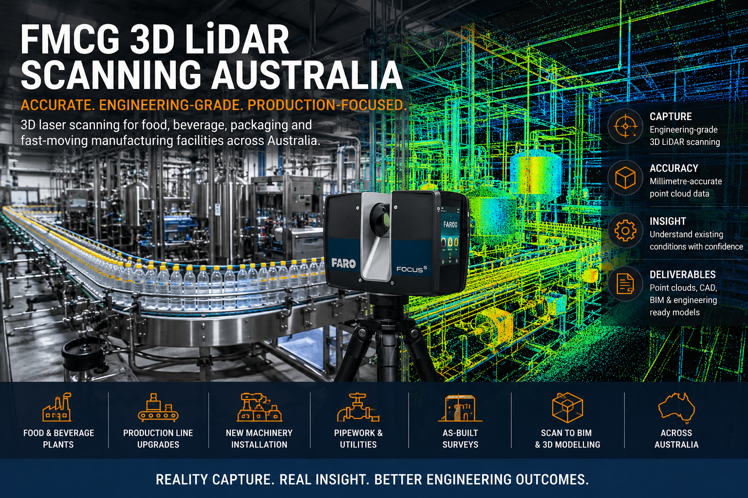
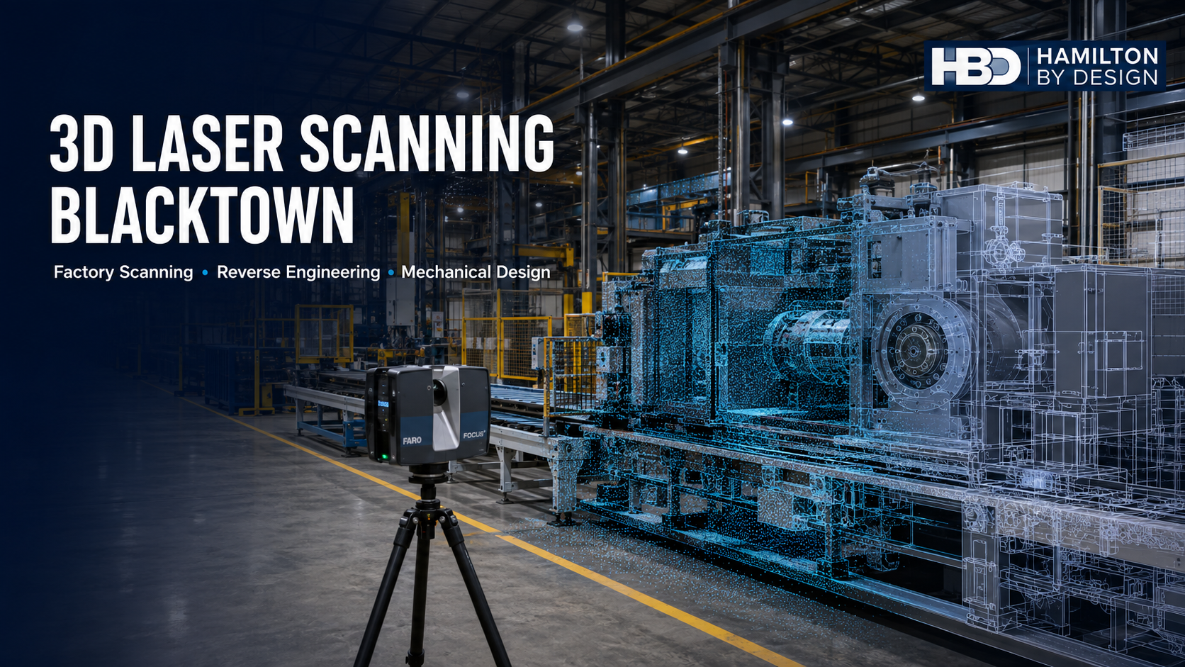
A 3D laser scan captures millions of measured points across visible surfaces. These points form a spatial dataset known as a point cloud. The point cloud can record the relative positions of machinery, building structures, platforms, pipework, conveyors, guards and other visible assets.
The result is a measurable representation of the facility at the time of capture.
What does factory scanning involve?
Factory scanning normally begins by defining the engineering purpose of the survey. This is important because scanning an entire facility for general documentation is different from capturing a machine interface for fabrication.
The required coverage, accuracy, level of detail and output format should be established before site work begins.
A typical industrial scanning process involves:
- Reviewing the project scope and available drawings.
- Identifying critical equipment, interfaces and access restrictions.
- Planning scanner positions around the operating facility.
- Capturing overlapping scans from multiple locations.
- Registering the scans into a coordinated point cloud.
- Checking the registration and relevant dimensions.
- Extracting the information required for engineering.
- Developing CAD models, layouts or fabrication drawings.
- Reviewing the outputs with the client.
- Retaining the approved engineering information for future projects.
Hamilton By Design can convert captured information through its point-cloud-to-CAD engineering workflow.
The required CAD output may be a simplified equipment envelope, a detailed machinery model, a two-dimensional factory layout or a coordinated three-dimensional representation. The appropriate output depends on what decisions the client needs to make.
It is also important to recognise that no scanning method captures surfaces that cannot be seen from a scanner position. Occluded areas, internal components and highly reflective or transparent surfaces may require additional scanner positions, handheld scanning, conventional measurement or temporary equipment access.
Brownfield factory upgrades
A brownfield project involves modifying an existing facility rather than designing an entirely new one. These projects can be difficult because the designer must work around installed equipment, operational constraints, existing structures and limited shutdown windows.
In Blacktown’s established industrial precincts, many engineering projects are brownfield by nature. Examples include:
- Installing a new packaging machine
- Replacing a conveyor
- Adding a robotic production cell
- Extending a mezzanine or access platform
- Modifying a dust-extraction system
- Relocating a machine between factories
- Adding guards to legacy equipment
- Reconfiguring a warehouse dispatch area
- Increasing production capacity within an existing building
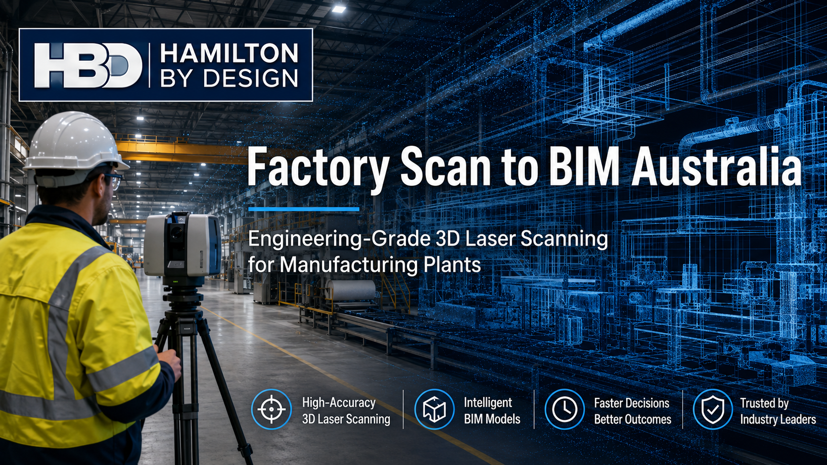
Hamilton By Design’s factory Scan-to-BIM services can help project teams coordinate new equipment with the existing building and plant.
A scanned model can be used to assess installation paths, identify spatial conflicts and examine whether maintenance access will remain available after the new equipment is installed. This reduces dependence on assumptions and allows potential problems to be addressed before fabrication begins.
Reverse engineering machinery and components
Many manufacturers continue to operate reliable machinery long after the original supplier has stopped supporting it. Drawings may be unavailable, and replacement parts may have long lead times or no longer be manufactured.
In these circumstances, reverse-engineering 3D scanning can support the development of replacement components and machinery documentation.
The process generally involves:
- Inspecting the component and understanding its function
- Capturing the accessible geometry
- Identifying worn, damaged or distorted areas
- Comparing repeated or symmetrical features
- Reconstructing the likely original design intent
- Developing a parametric CAD model
- Selecting materials and manufacturing processes
- Applying tolerances and fits
- Preparing manufacturing and inspection drawings
A scan records the condition of a component as found. It does not automatically identify the component’s original nominal dimensions. Engineering judgement is required to distinguish intentional geometry from wear, corrosion, damage and manufacturing variation.
This is why reverse engineering should not be treated simply as a software conversion exercise. The component’s loads, interfaces, material, function and failure consequences must also be considered.
Mechanical drafting and fabrication drawings
Accurate site capture is only one part of an engineering project. Fabricators and installers need clear, controlled documentation that explains what must be manufactured.
Hamilton By Design provides mechanical drafting services in Sydney for machinery, components, frames, guards, platforms and industrial modifications.
Depending on the scope, a drawing package may contain:
- General arrangement drawings
- Parts and assembly drawings
- Fabrication drawings
- Bills of materials
- Weld details
- Material specifications
- Surface treatments and finishes
- Fits and tolerances
- Critical dimensions
- Installation information
- Revision records
- As-built documentation
Mechanical drawings may be developed with reference to the AS 1100 technical drawing series. Structural steel fabrication may also require consideration of AS 4100, AS/NZS 5131 and the relevant parts of the AS/NZS 1554 welding series.
Standards should not be added to drawings as generic notes without assessing whether they apply. The appropriate standard, execution requirements and acceptance criteria should be established for the particular equipment and project.
Machinery guarding and plant safety
Factories contain rotating shafts, chains, belts, gears, cutters, conveyors, presses, automated cells and other potentially hazardous plant. Older machinery may have been designed before contemporary safeguarding practices became widely adopted, while modified machinery may have developed new hazards that were not present in its original configuration.
Hamilton By Design offers machine-guarding design and engineering to support new guards, existing-guard reviews and machinery modifications.
A practical guarding assessment may consider:
- Access to moving parts
- In-running nip points
- Entanglement hazards
- Crushing and shearing zones
- Guard openings and safety distances
- Fixed and movable guards
- Interlocks
- Emergency-stop access
- Stored energy
- Maintenance and cleaning tasks
- Visibility of the process
- Ergonomics and manual handling
- Safe isolation requirements
- Residual risks
In NSW, machinery safety responsibilities arise under the Work Health and Safety framework. The AS/NZS 4024 series provides recognised technical guidance for machinery risk assessment, risk reduction, safeguarding, interlocks, safety distances and related design matters.
Conveyor projects may also require consideration of AS/NZS 4024.3610. Although the older AS 1755 conveyor standard remains visible in historical plant documents, its current status and the application of the AS/NZS 4024 conveyor requirements should be checked when developing new work.
Laser scanning can assist guarding projects by recording the relationship between the hazard, the machinery, existing structures and operator access. However, scanning does not replace a risk assessment. The point cloud supplies spatial evidence; the engineering assessment determines what controls are required.
Mechanical design and engineering verification
After the existing conditions have been captured, Hamilton By Design can develop machinery modifications, frames, brackets, guards, platforms and other mechanical solutions.
Where appropriate, SolidWorks finite element analysis can be used to examine stress, displacement and load paths before a design is released for fabrication.
FEA may assist with:
- Comparing alternative frame arrangements
- Assessing machinery-support structures
- Reviewing lifting attachments
- Checking brackets and equipment supports
- Investigating local stress concentrations
- Evaluating changes to an existing design
- Understanding deformation under operating loads
FEA results depend on the quality of the assumptions used. Loads, restraints, material properties, contacts and operating conditions must reasonably represent the real system. Simulation should therefore support engineering judgement rather than replace it.
Engineering opportunities in logistics facilities
Blacktown and Eastern Creek contain major warehouse and distribution operations. These facilities increasingly rely on conveyors, pallet systems, automated handling equipment, storage racking and high-volume vehicle movements.
Potential engineering projects include:
- Conveyor modifications
- Parcel-handling equipment layouts
- Pallet-transfer systems
- Equipment-support frames
- Access platforms and stairs
- Loading-area arrangements
- Forklift and pedestrian separation
- Protective barriers
- Storage-racking coordination
- Maintenance-access studies
- Guarding and isolation reviews
Three-dimensional scanning can establish the locations of columns, walls, doors, fire services, existing conveyors and racking. Proposed equipment can then be positioned within the model to evaluate clearances and conflicts.
Depending on the project, relevant references may include AS/NZS 4024.3610 for conveyors, AS 4084 for steel storage racking, AS 4991 for lifting devices, the AS 1418 crane series and the AS 2550 safe-use series.
Retaining factory point clouds and engineering records
The long-term value of factory scanning increases when the resulting information is properly managed.
Hamilton By Design can retain project information such as:
- Registered factory point clouds
- Machinery layouts
- Component scans
- Native CAD models
- Exchange-format models
- Fabrication drawings
- Guarding layouts
- Risk-assessment records
- Modification histories
- Superseded and approved revisions
A retained point cloud can provide a baseline for future factory changes. When another project begins, the engineering team may already have much of the surrounding spatial information needed for preliminary planning.
Data-management arrangements should define ownership, permitted access, file formats, retention periods, revision status and cybersecurity responsibilities. Clients should also understand whether an archived model is a general reference, a verified engineering model or a formal as-built record.
A practical engineering workflow for Blacktown manufacturers
For many Blacktown industrial clients, the greatest benefit comes from combining several services rather than commissioning scanning, design and drafting as unrelated activities.
An integrated workflow can proceed from:
Site capture → point cloud → engineering assessment → CAD design → safety review → fabrication drawings → installation support → retained asset record
This approach reduces the number of information handovers and helps preserve the connection between the physical factory and the final design.
Hamilton By Design’s engineering studies and assessments can help clients investigate existing conditions and define practical options before committing to detailed design or fabrication.
Frequently asked questions
What is 3D laser scanning?
3D laser scanning is a reality-capture method that records the spatial position of visible surfaces. The captured measurements form a point cloud representing machinery, structures, services and other objects within the scanner’s field of view.
Can a point cloud be used directly for fabrication?
Usually, the point cloud should first be interpreted and converted into controlled engineering geometry. Fabricators typically require dimensioned drawings, tolerances, materials, weld details and clearly defined interfaces. A raw point cloud does not contain all this design information.
Can Hamilton By Design scan an operating factory?
In many cases, yes. The scanning plan should consider production activities, exclusion zones, moving machinery, site inductions and the visibility of critical equipment. Some areas may require planned access or a short production interruption.
How accurate is 3D laser scanning?
Accuracy depends on the scanner, range, surface properties, registration method, site conditions and project-control requirements. The necessary accuracy should be defined according to the engineering task. A broad factory layout and a close-tolerance replacement component do not require the same capture method.
Can 3D scanning replace all manual measurements?
No. Scanning is highly effective for complex visible geometry, but critical interfaces may still require physical verification. Hidden surfaces, internal features, threads, fits and inaccessible areas may need conventional measurement, disassembly or supplementary scanning.
Can worn components be reverse engineered?
Yes, but the scan will include wear and damage. The engineer must reconstruct the likely original geometry using functional interfaces, symmetry, repeated features, engineering calculations and available historical information.
Does scanning confirm that a machine is safe?
No. Scanning documents geometry and existing conditions. Machinery safety requires hazard identification, risk assessment and the selection of appropriate controls. Scanning can support this work by providing accurate spatial information.
What information can be produced from a factory scan?
Possible deliverables include registered point clouds, equipment layouts, sections, elevations, CAD models, clearance studies, clash reviews, machinery models, guarding layouts and fabrication drawings.
Which Australian Standards apply?
The applicable standards depend on the equipment and scope. Common references may include the AS/NZS 4024 machinery-safety series, AS 1100 technical drawing series, AS 4100, AS/NZS 5131, AS/NZS 1554, AS 4084 and relevant conveyor, lifting or access standards. The current edition and amendments should be confirmed for every project.
Can Hamilton By Design retain the scanning and CAD data?
Yes, project arrangements can include retention of point clouds, CAD models and drawings. The agreed system should define ownership, access, revision control, retention periods and whether the stored information has been verified as an as-built record.
Supporting Blacktown’s changing industrial landscape
Blacktown’s manufacturers, machine shops, construction-product businesses and logistics operators work in facilities where accurate information directly affects cost, safety and production continuity.
Engineering-led 3D laser scanning provides a practical way to capture existing conditions, reduce dimensional uncertainty and support better-informed design decisions. When scanning is integrated with reverse engineering, mechanical design, machinery safety and fabrication drafting, the result is not merely a digital image of the factory. It becomes usable engineering information.
Hamilton By Design can support Blacktown and Western Sydney clients from the initial factory scan through to CAD modelling, engineering assessment, guarding design and manufacturing documentation.
For businesses planning a factory upgrade, machinery modification, production-line relocation or reverse-engineering project, establishing an accurate understanding of the existing conditions is the logical place to begin.

Contact Us – Talk To Us
Our clients: