SolidWorks 3D Modelling Services

High-accuracy engineering design for mining, fabrication, and industrial projects across Australia

At Hamilton By Design, SolidWorks is at the core of everything we do. From detailed 3D modelling and mechanical design to FEA verification and fabrication-ready deliverables, our SolidWorks workflows support safe, efficient, and accurate engineering outcomes for complex brownfield and greenfield projects.

Whether we are laser-scanning a CHPP plant room, reverse-engineering a structural component, developing new mechanical assemblies, or verifying fit-ups using clash detection, SolidWorks allows us to transform real-world conditions into engineered, dependable solutions.


3D LiDAR scanning and 3D modelling service button โ€” laser scanner capturing a point cloud for engineering and CAD modelling
Mechanical engineering services

Why SolidWorks Matters for Your Project

SolidWorks enables us to deliver higher accuracy, faster turnaround times, and better quality engineering documentation. When combined with our 3D LiDAR scanning and digital engineering workflows, SolidWorks becomes a powerful tool for:

  • Retrofitting and upgrade projects
  • Brownfield plant modifications
  • Structural and mechanical design
  • Reverse engineering of existing components
  • Fabrication drawing creation
  • Pipe routing and equipment layout
  • General arrangement (GA) development
  • Clash detection and interference checks

The result: fewer site surprises, reduced fabrication rework, and more predictable installation outcomes.


Our SolidWorks Capabilities

1. Advanced 3D Modelling

We build accurate, parametric 3D models for mechanical, structural, piping, and equipment systems. Models can be created from:

  • 3D LiDAR point clouds
  • Existing drawings
  • Physical measurements
  • Legacy data or supplier information

These models form the foundation for engineering design, fabrication deliverables, and digital twin development.


2. Engineering Design & Mechanical Development

Hamilton By Design provides full mechanical design support using SolidWorks, including:

  • Concept development
  • Detailed part and assembly design
  • Mechanism and motion analysis
  • Equipment layout planning
  • Design-for-manufacture (DFM) optimisation

We design with fabrication, installation, and long-term maintenance in mind.


3. Structural Modelling & Verification

Using SolidWorks and SolidWorks Simulation, we support structural engineering tasks such as:

  • Steelwork design
  • Platform and walkway modelling
  • Equipment support frames
  • Brackets, mounts, and tie-ins
  • Baseplates and skid packages

Models are used to check clashes, verify site conditions, and support safe installation planning.


4. FEA & Engineering Verification

SolidWorks Simulation allows us to perform engineering checks on components and structures, including:

  • Stress analysis (von Mises, principal stress)
  • Deflection modelling
  • Connection and bolt verification
  • Fatigue checks
  • Material comparison
  • Load path assessments

These studies ensure designs meet engineering standards and withstand real-world operating conditions.


5. Fabrication Drawings & Deliverables

We produce clear, accurate drawings for fabrication, workshop use, and installation teams:

  • Part drawings
  • Assembly drawings
  • DXF files for profiling
  • Welded assemblies
  • Cutting lists and BOMs
  • Marking plans
  • Site installation drawings

All drawings are generated directly from the master SolidWorks model to ensure consistency and reduce rework.


6. Scan-to-SolidWorks: Turning Point Clouds into Engineering Models

Our digital engineering workflow combines:

LiDAR Scan โ†’ Point Cloud โ†’ SolidWorks Model โ†’ Drawings & FEA

This allows us to:

  • Validate brownfield conditions
  • Reduce tape-measure errors
  • Check fit-up accuracy before fabrication
  • Avoid clashes during installation
  • Provide true โ€œas-builtโ€ engineering context

This is one of Hamilton By Designโ€™s strongest capabilities โ€” and a major value driver for complex industrial environments.

SOLIDWORKS Professional Design certification badge by Dassault Systรจmes
SOLIDWORKS Professional Drawing Tools certification badge by Dassault Systรจmes

Our clients:

Industries We Support

SolidWorks is used across every sector Hamilton By Design services, including:

  • Mining & mineral processing
  • CHPP wash plants
  • Heavy industrial facilities
  • Fabrication workshops
  • Government infrastructure
  • Construction & modular buildings
  • Water and utility sectors

From bucket-wheel reclaimers to pump skids, conveyors, tanks, chutes, walkways, platforms, and complete plant rooms โ€” SolidWorks allows us to deliver accurate, validated engineering models for real-world conditions.



Hamilton By Design logo displayed on a blue tilted rectangle with a grey gradient background
3D LiDAR scanning and 3D modelling service button โ€” laser scanner capturing a point cloud for engineering and CAD modelling
Mechanical engineering services

Name
Would you like us to arrange a phone consultation for you?
Address

3D CAD Modelling Australia service banner for Hamilton By Design
3D LiDAR scanning and 3D modelling service button โ€” laser scanner capturing a point cloud for engineering and CAD modelling
Mechanical engineering services
Mechanical drafting services button
Blue rounded button with the text โ€œSolidWorks Designโ€ in white.
Blue banner graphic displaying the text "Point Cloud to CAD - Australia" in large white lettering, representing point cloud processing, scan-to-CAD conversion and digital engineering services across Australia.
Mechanical, Structural & Pipework Drafting service banner by Hamilton By Design featuring white text on a blue background.
Engineering Governance title graphic featuring bold white text reading "Engineering Governance" centred on a blue rounded rectangle background.
Mining Plant Upgrades promotional graphic with bold white text on a blue background representing mining infrastructure, plant improvement, and engineering upgrade projects.
3D Pipework promotional graphic with bold white text on a blue background representing pipework design, modelling, drafting, and engineering services.
Australian Drafting logo featuring bold white text reading "Australian Drafting" centred on a blue rounded rectangle background.
3D Pipework promotional graphic with bold white text on a blue background representing pipework design, modelling, drafting, and engineering services.
Mining Plant Upgrades promotional graphic with bold white text on a blue background representing mining infrastructure, plant improvement, and engineering upgrade projects.
3D LiDAR Scanning for Engineering Projects title graphic featuring bold white text on a blue rounded rectangle background.
Australian Drafting logo featuring bold white text reading "Australian Drafting" centred on a blue rounded rectangle background.
Engineering Governance title graphic featuring bold white text reading "Engineering Governance" centred on a blue rounded rectangle background.
Mechanical, Structural & Pipework Drafting service banner by Hamilton By Design featuring white text on a blue background.
Mechanical engineering services
Blue rounded button with the text โ€œSolidWorks Designโ€ in white.
Finite Element Analysis (FEA) engineering simulation button

3D Scanning Sydney banner promoting engineering-grade 3D laser scanning, LiDAR scanning, and reality capture services by Hamilton By Design.
Mechanical Engineering Sydney banner with white text on a blue background representing Hamilton By Design's mechanical engineering services in Sydney.
Mechanical Drafting and 3D Modelling Sydney banner highlighting Hamilton By Design's CAD drafting, 3D modelling, and engineering design services in Sydney.

Mechanical Engineering | Structural Engineering


Mechanical Engineers in Wyong

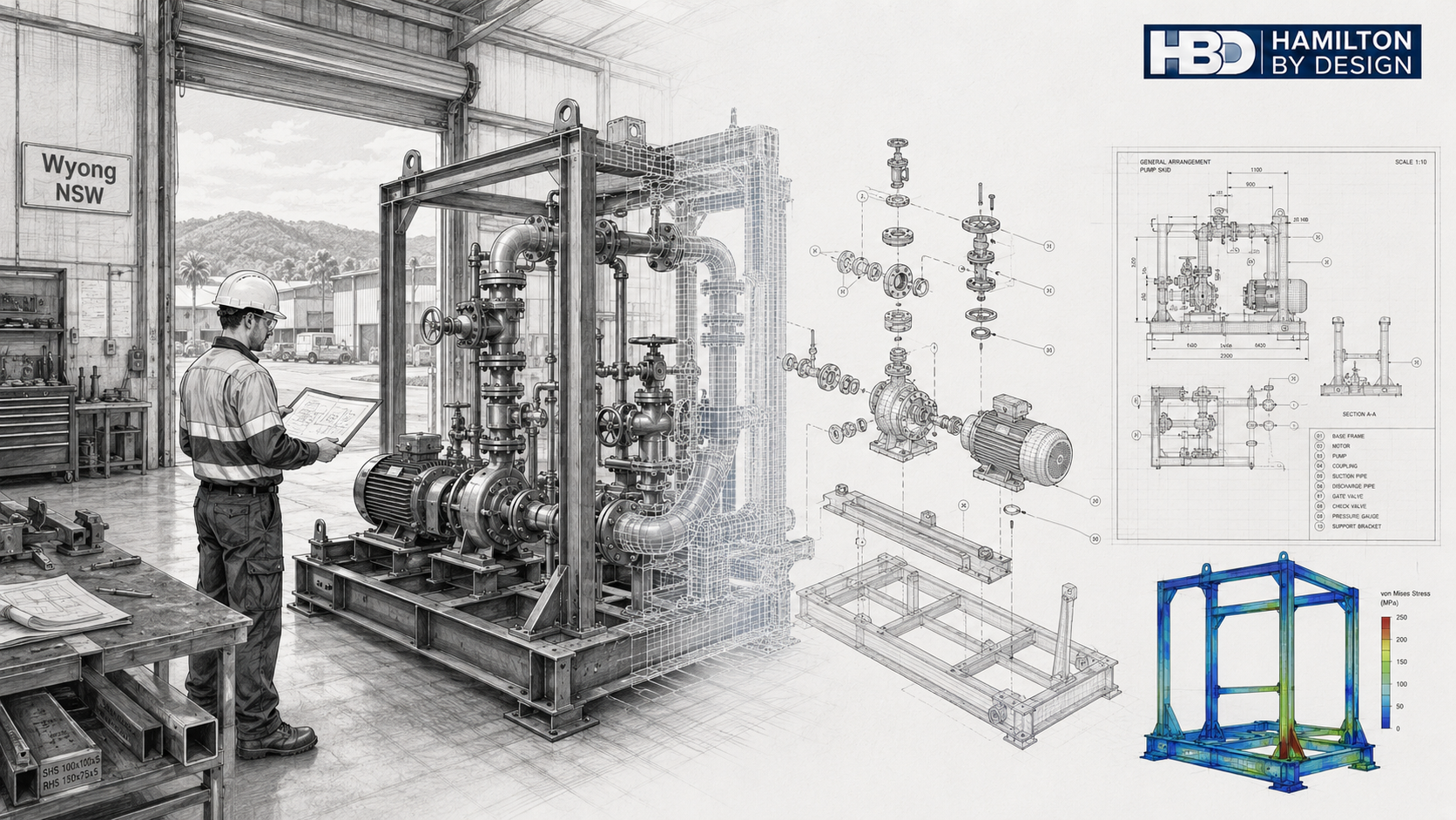
Mechanical engineer reviewing a pump and pipework skid in a Wyong workshop, with CAD wireframe, exploded aassembly, fabrication drawings and FEA analysis.

Innovative Design and Engineering Solutions

At Hamilton By Design, we are a team of degree-qualified mechanical engineers in Wyong, providing expert design, analysis, and build services for mechanical systems across the Central Coast and Hunter regions. We specialise in engineering design, mechanical systems integration, and prototype development โ€” not car repair or automotive servicing.

Our goal is simple: to design and deliver engineered systems that perform efficiently, safely, and reliably under real operating conditions.

Your Local Mechanical Engineering Specialists

Being locally based in Wyong allows us to deliver responsive, practical engineering solutions that suit regional industries. We understand the Central Coastโ€™s industrial landscape โ€” from manufacturing to infrastructure โ€” and provide mechanical engineering support tailored to each clientโ€™s specific operational and compliance needs.

Our services include:

  • Mechanical design and system modelling
  • 3D CAD drafting, assemblies, and technical documentation
  • Finite Element Analysis (FEA) and performance simulation
  • Prototype design, testing, and system optimisation
  • Fabrication support and workshop documentation
  • Process improvement and energy efficiency solutions
  • Structural-mechanical integration for equipment and machinery

Whether itโ€™s a custom mechanical assembly, plant upgrade, or new industrial installation, our engineers combine practical trade awareness with solid analytical expertise to ensure every solution works in the real world.


Why Businesses in Wyong Choose Us

Choosing a local mechanical engineering company in Wyong means partnering with professionals who know local suppliers, fabrication standards, and site conditions. We bring the precision of professional engineering to projects of all sizes while remaining approachable and cost-effective.
Our approach ensures each design is:

  • Safe: Compliant with Australian Standards and industry codes
  • Efficient: Engineered for performance and energy conservation
  • Maintainable: Designed with accessibility and lifecycle costs in mind
  • Economical: Delivering long-term value for the client

From the first sketch to the final bolt, our work reflects engineering discipline, accuracy, and accountability.


Our Engineering Process

Every project follows a structured, documented workflow that ensures consistency and quality:

  1. Concept and Feasibility โ€“ We define project scope, functional requirements, and design objectives through collaboration with clients and stakeholders.
  2. Design and Simulation โ€“ Using modern CAD platforms and FEA tools, we model real-world forces, stresses, and flows to optimise performance and safety.
  3. Verification and Prototyping โ€“ Our team validates designs with prototypes, testing, or detailed fabrication drawings.
  4. Implementation Support โ€“ We assist with workshop drawings, fabrication coordination, and commissioning.
  5. Lifecycle and Maintenance Review โ€“ Our post-installation support ensures long-term reliability and efficiency.

This process ensures traceability, compliance, and confidence at every stage of delivery.


Snapshot: Local Industries and Organisations We Support

Our experience extends across a wide range of local companies, manufacturers, and government organisations throughout Wyong and the Central Coast.

Here are some examples of the types of organisations we work with and the engineering value we bring:

Industrial and Manufacturing Clients

  • Donaldson Australasia (North Wyong) โ€“ A leading industrial filtration manufacturer. Our expertise supports the design and integration of mechanical handling, test rigs, and equipment frames for production systems.
  • Plateau Food Distributors (Wyong) โ€“ Food processing and cold storage facilities often rely on mechanical systems for refrigeration, materials handling, and ventilation. We assist with system design, structural support frames, and energy optimisation.
  • Fabrication and Alloy Manufacturers such as Manufactured Alloy Xtras โ€“ We provide structural design, stress analysis, and welding procedure documentation for aluminium and steel assemblies.
  • General Manufacturers and Industrial Workshops in the Wyongโ€“Tuggerah area โ€“ We support local businesses with prototype development, mechanical jigs, and tooling systems designed to Australian Standards.

Government and Public Infrastructure

  • Central Coast Council (formerly Wyong Shire Council) โ€“ Responsible for infrastructure, public buildings, and community assets. Our services include mechanical design for pumping stations, HVAC systems, and public facility upgrades.
  • NSW Infrastructure Projects (e.g. Pacific Highway Upgrade) โ€“ Large-scale transport and civil projects often require custom mechanical and structural integration. We assist contractors and consultants with system modelling and compliance documentation.
  • TAFE NSW โ€“ Wyong Campus โ€“ Facilities such as laboratories, animal care centres, and trade workshops require mechanical system design for ventilation, process equipment, and utilities.
  • Water and Wastewater Services โ€“ We provide engineering input on pumping systems, pipework layouts, and mechanical components for water infrastructure projects.

These partnerships reflect our capability to operate across both private and public sectors, supporting projects that range from individual components to fully integrated mechanical systems.


Our Capabilities and Technologies

Our engineers use industry-leading tools and software to ensure precision and compliance:

  • 3D CAD Modelling (SolidWorks, Autodesk Inventor, Fusion 360)
  • Finite Element Analysis (FEA) for stress and load validation
  • Computational Fluid Dynamics (CFD) for flow and heat transfer
  • P&ID and Mechanical Schematics for complex systems
  • Project Documentation including Bill of Materials (BOMs) and fabrication drawings

By combining digital design with engineering expertise, we can quickly move from concept to prototype, minimising rework and ensuring the design meets its operational goals.


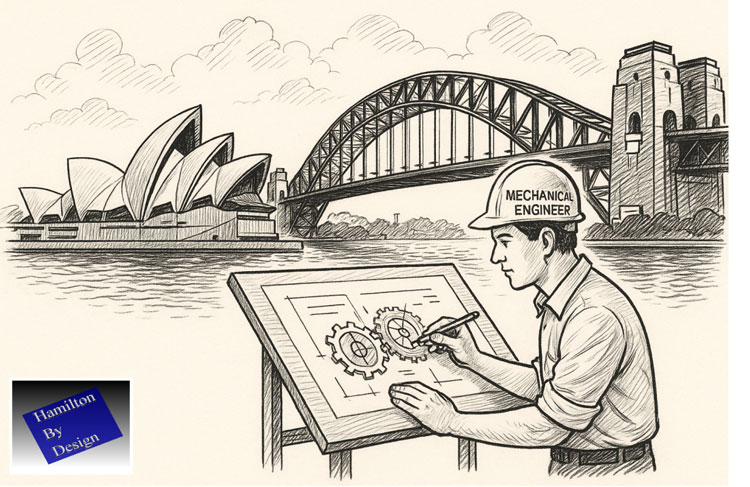
Illustrated mechanical engineer drafting technical gear drawings at a workstation with the Sydney Opera House and Harbour Bridge in the background, alongside the Hamilton By Design logo

Commitment to Engineering Excellence

Every project we deliver reflects our core principles:

  • Technical Integrity โ€“ Our engineers work to the highest professional standards.
  • Innovation โ€“ We continuously refine designs using simulation, prototyping, and feedback.
  • Safety and Compliance โ€“ We align with AS/NZS codes and WHS regulations in every design.
  • Sustainability โ€“ We promote energy-efficient design and reduced material waste through smart engineering.

Our clients appreciate that we think like engineers and communicate like partners. We bring clarity, technical rigour, and creativity to every project.


Contact Your Local Mechanical Engineers in Wyong

If youโ€™re searching for mechanical engineers in Wyong who can design, analyse, and build high-performance mechanical systems, Hamilton By Design is your trusted local partner.

We are not automotive mechanics โ€” we are qualified mechanical engineers who design and deliver engineered solutions that move industries forward.

Hamilton By Design logo displayed on a blue tilted rectangle with a grey gradient background

Phone: 047 700 2249
Email: [email protected]
Location: Wyong, NSW

Letโ€™s talk about your next project and discover how professional mechanical design can improve reliability, efficiency, and safety in your operations.

Mechanical Engineering | Structural Engineering

3D LiDAR scanning services on the Central Coast providing engineering-grade laser scanning, point cloud capture, scan-to-CAD modelling and industrial reality capture for infrastructure and industrial projects.
Drafting services on the Central Coast providing engineering drawings, fabrication detailing, as-built documentation, reverse engineering and CAD drafting for industrial and infrastructure projects.
Mechanical engineering services on the Central Coast providing industrial design, plant inspections, pump calculations, reverse engineering and engineering support for manufacturing, infrastructure and heavy industry projects.

Mechanical Drafting | Structural Drafting

3D CAD Modelling | 3D Scanning

Chute Design

SolidWorks Contractors in Australia

Hamilton By Design โ€“ Blog

Custom Designed – Shipping Containers

Coal Chute Design

Mechanical Engineers in Sydney

Engineering Design & Build Services | Hamilton By Design

Our clients:


3D Scanning Sydney banner promoting engineering-grade 3D laser scanning, LiDAR scanning, and reality capture services by Hamilton By Design.
Mechanical Engineering Sydney banner with white text on a blue background representing Hamilton By Design's mechanical engineering services in Sydney.
Mechanical Drafting and 3D Modelling Sydney banner highlighting Hamilton By Design's CAD drafting, 3D modelling, and engineering design services in Sydney.

Mechanical Engineering | Structural Engineering


Engineering Confidence: Using FEA to Validate Real-World Designs

Mechanical engineering has always been a balance between creativity and certainty.
Every bracket, frame, chute, or structural support we design must perform under real loads, temperatures, and conditions โ€” often in environments where failure simply isnโ€™t an option.

Thatโ€™s where Finite Element Analysis (FEA) earns its place as one of the most powerful tools in modern design. It allows engineers to move from assumption to verification โ€” transforming the way we predict, test, and optimise mechanical systems.


What Is FEA โ€” and Why It Matters

FEA divides complex geometry into a network of small, interconnected elements.
By solving the physical equations that govern stress, strain, and displacement across those elements, engineers can predict how a structure behaves under load, vibration, or temperature.

Instead of relying solely on hand calculations or over-built safety factors, FEA provides quantitative insight into performance โ€” letting us see where structures flex, where stress concentrates, and how design choices affect real-world outcomes.

In mechanical engineering, that means fewer prototypes, lower material costs, and far greater design confidence.


1. Static Analysis โ€” The Foundation of Structural Validation

Static linear analysis is the foundation of most FEA work.
It evaluates how a structure responds to steady, time-independent loads such as gravity, pressure, or fixed equipment weight.

Through static analysis, engineers can:

  • Visualise stress and displacement distribution across a part or assembly.
  • Evaluate safety factors under different loading conditions.
  • Check stiffness and material utilisation before fabrication.
  • Identify weak points or stress concentrations early in design.

This baseline validation is the difference between a design that โ€œshouldโ€ work and one that will.


2. Assembly-Level Simulation โ€” Seeing the Whole System

Few machines fail because a single part breaks.
Most failures happen when components interact under load โ€” bolts shear, brackets twist, or welds experience unplanned tension.

FEA allows engineers to simulate entire assemblies, including:

  • Contact between parts (bonded, sliding, or frictional).
  • Realistic boundary conditions such as bearings, springs, or pinned joints.
  • The influence of welds, fasteners, or gaskets on overall performance.

This system-level view helps mechanical engineers design not only for strength, but also for compatibility and reliability across the full structure.


3. Mesh Control โ€” Accuracy Where It Counts

A simulation is only as good as its mesh.
By controlling element size and density, engineers can capture critical detail in stress-sensitive regions like fillets, bolt holes, and weld toes.

Modern FEA tools use adaptive meshing โ€” refining the model automatically in areas of high stress until the solution converges.
That means precise, efficient results without excessive computation time.


4. Thermal-Structural Interaction โ€” When Heat Becomes a Load

Many mechanical systems face thermal as well as mechanical challenges.
Whether itโ€™s ducting in a process plant or hoppers near heat sources, temperature gradients can cause expansion, distortion, or thermal stress.

FEA allows engineers to:

  • Model steady-state or transient heat transfer through solids.
  • Apply convection, radiation, or temperature boundary conditions.
  • Combine thermal and structural analyses to study thermal expansion and thermal fatigue.

Understanding how heat and load combine helps ensure equipment remains stable, safe, and accurate throughout its lifecycle.


5. Modal and Buckling Analysis โ€” Designing Against Instability

Some risks are invisible until theyโ€™re simulated.
Vibration and buckling are two of the most overlooked โ€” yet most common โ€” causes of structural failure.

Modal Analysis

Determines a structureโ€™s natural frequencies and mode shapes, helping designers avoid resonance with operating machinery, fans, or conveyors.

Buckling Analysis

Predicts the critical load at which slender members or thin-walled panels lose stability โ€” allowing engineers to reinforce and optimise designs early.

By identifying these limits before fabrication, engineers can prevent problems that are expensive and dangerous to discover on site.


Design Optimisation โ€” Smarter, Lighter, Stronger

Good design is rarely about adding material; itโ€™s about using it wisely.
FEA supports parametric and goal-based optimisation, enabling engineers to vary geometry, thickness, or material and automatically test multiple configurations.

You can set objectives such as:

  • Minimising weight while maintaining strength.
  • Reducing deflection under fixed loads.
  • Optimising gusset or flange size for stiffness.

This process of โ€œdigital lightweightingโ€ drives better performance and cost efficiency โ€” especially valuable in industries where both material and downtime are expensive.


7. Communication and Confidence

FEA isnโ€™t only a calculation tool โ€” itโ€™s a communication tool.
Colour-coded plots, animations, and automated reports make it easier to explain complex mechanical behaviour to project managers, clients, or certifying bodies.

Clear visuals turn stress distributions and displacement fields into a shared language โ€” helping stakeholders understand why certain design choices are made.


Real-World Applications Across Mechanical Engineering

ApplicationType of AnalysisKey Benefit
Chutes & HoppersStatic + BucklingConfirm wall thickness and frame design for structural load and vibration
Conveyor FramesModal + StaticAvoid resonance and ensure adequate stiffness
Pressure EquipmentThermal + StaticEvaluate thermal stress and hoop stress under load
Machine BracketsStatic + OptimisationReduce weight while maintaining rigidity
Platforms & GuardingBucklingValidate stability under safety loading
Welded Frames & SupportsStaticCheck deformation, stress, and weld performance

These examples show how FEA becomes an everyday design partner โ€” embedded in the workflow of mechanical engineers across manufacturing, resources, and infrastructure.


The Engineerโ€™s Advantage: Data Over Assumption

In traditional design, engineers often relied on prototypes and conservative safety factors.
Today, simulation delivers the same assurance โ€” without the waste.

By applying FEA early in the design cycle, mechanical engineers can:

  • Predict failure modes before they occur.
  • Shorten development time.
  • Reduce material usage.
  • Justify design decisions with quantitative proof.

FEA enables engineers to focus less on guesswork and more on innovation โ€” designing structures that are both efficient and dependable.


Engineering Integrity in Practice

At Hamilton By Design, we integrate FEA into every stage of mechanical design and development.
Itโ€™s how we ensure that every frame, chute, and mechanical system we deliver performs as intended โ€” safely, efficiently, and reliably.

We use FEA not just to find the limits of materials, but to push the boundaries of design quality โ€” delivering engineering solutions that last in the toughest industrial environments.

Design backed by data isnโ€™t a slogan โ€” itโ€™s how we engineer confidence.


Building a Culture of Verified Design

When FEA becomes part of everyday engineering culture, it changes how teams think.
Designers begin to see structures not just as drawings, but as living systems under real forces.

That shift builds trust โ€” between engineer and client, between concept and reality.
Itโ€™s what defines the future of mechanical design: informed, optimised, and proven before the first bolt is tightened.

3D LiDAR scanning and 3D modelling service button โ€” laser scanner capturing a point cloud for engineering and CAD modelling
Mechanical engineering services
Finite Element Analysis (FEA) engineering simulation button
Mechanical engineering services

3D Scanning Sydney banner promoting engineering-grade 3D laser scanning, LiDAR scanning, and reality capture services by Hamilton By Design.
Mechanical Engineering Sydney banner with white text on a blue background representing Hamilton By Design's mechanical engineering services in Sydney.
Mechanical Drafting and 3D Modelling Sydney banner highlighting Hamilton By Design's CAD drafting, 3D modelling, and engineering design services in Sydney.

Mechanical Engineering | Structural Engineering


Lessons from a Landmark Case:

The Importance of Robust Structural Design Review

In 2024, SafeWork SA concluded a landmark case involving a spectator-roof collapse during a football club redevelopment project in South Australia. While no life-threatening injuries occurred, the incident highlighted how critical it is for design, review, and certification processes to work together to ensure safety on site.

This was the first successful design-related prosecution under South Australiaโ€™s Work Health and Safety Act, sending a clear signal to the engineering and construction sector: design decisions carry legal and safety obligations, not just technical ones.

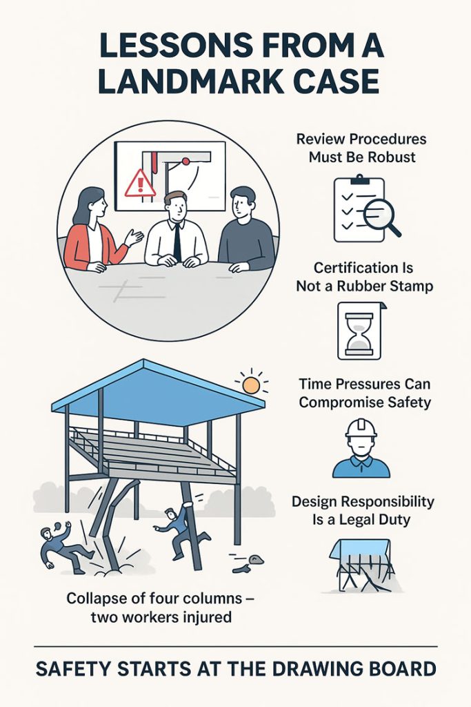
Infographic titled โ€œLessons from a Landmark Case,โ€ showing engineers reviewing a design, icons highlighting robust review procedures, proper certification, time-pressure risks, and legal design responsibilities. The lower illustration depicts a structure collapsing after four column failures with two workers falling, emphasising the message โ€œSafety starts at the drawing board

What Happened (Briefly)

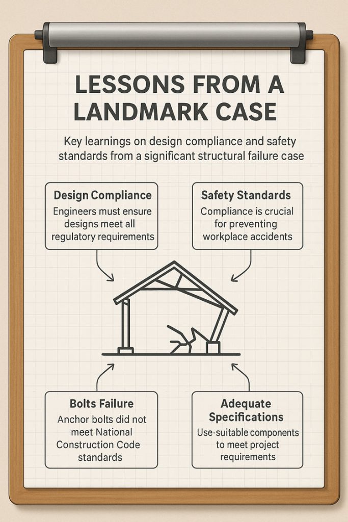
During roof sheeting works in late 2021, four of seven supporting columns of a cantilevered spectator roof failed, causing two apprentices to slide down the roof sheets. SafeWork SAโ€™s investigation found that the anchor bolts specified for the column base plates were inadequate and did not meet the requirements of the National Construction Code (NCC).

An independent compliance review also failed to detect this issue, allowing the error to pass unchecked into construction. The result was a collapse that could have had far more severe consequences had the roof been fully loaded or occupied.

Key Learnings for the Industry

This case underscores several important lessons for engineers, designers, project managers, and certifiers:

1. Design Responsibility Is a WHS Duty

Under the WHS Act, designers have a duty to ensure their work is safe not just in its intended use, but during construction. This means bolts, connections, and base plates must be designed for real-world loads โ€” including wind uplift, combined shear and tension, and concrete breakout limits per NCC and relevant Australian Standards.

2. Review Procedures Must Be Robust โ€” and Followed

Having a documented review procedure is not enough if it isnโ€™t rigorously applied. Independent verification and internal peer review are critical to catching design errors before they reach site.

3. Certification Is Not a Rubber Stamp

Independent certifiers play a key role in safeguarding public safety. They must actively verify that designs meet compliance, rather than simply sign off on documentation.

4. Time Pressures Can Compromise Safety

Compressed project timelines were noted as a factor in missed opportunities to catch the error. Project teams must resist the temptation to shortcut review steps when schedules are tight โ€” safety must remain non-negotiable.

5. Documentation & Traceability Protect Everyone

Maintaining calculation records, checklists, and review signoffs creates a clear audit trail. This helps demonstrate due diligence if something goes wrong.

Infographic titled โ€˜Lessons From a Landmark Caseโ€™ displayed on a clipboard. It highlights key learnings from a structural failure case: design compliance, safety standards, bolts failure, and adequate specifications. At the centre is a simple line drawing of a collapsed structure, with arrows pointing to four labelled boxes describing the importance of regulatory compliance, workplace safety standards, anchor bolt failures, and using suitable components to meet project requirements

Why This Matters

The collapse at Angaston Football Club was a relatively small incident with minor injuries โ€” but it could easily have been catastrophic. By learning from cases like this, the industry can improve its processes and prevent future failures.

As professionals, our role is to design for safety, verify rigorously, and document clearly. Doing so protects workers, end-users, and our own organisations.

Legal & Ethical Considerations

This post is intended as a learning resource, not as an allocation of blame. The case referenced is a matter of public record through SafeWork SA and SAET decisions, and all commentary here focuses on general principles of safe design and compliance.

We recommend that other practitioners review their own QA and certification procedures in light of this case to ensure compliance with the National Construction Code and WHS obligations.

More Information —> The Advertiser / Adelaide Now

Hamilton By Design logo displayed on a blue tilted rectangle with a grey gradient background

Mechanical Engineering | Structural Engineering

Mechanical Drafting | Structural Drafting

3D CAD Modelling | 3D Scanning

Chute Design

SolidWorks Contractors in Australia

Hamilton By Design โ€“ Blog

Finite Element Analysis (FEA) engineering simulation button
Mechanical engineering services

Chute Design at Hamilton By Design

Chute Design at Hamilton By Design

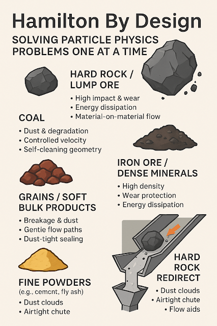
At Hamilton by Design, we see ourselves as more than engineers โ€” we are problem-solvers who bring both science and experience to the table. Every bulk material transfer is unique, and each one carries its own challenges. By combining the principles of particle physics with decades of hands-on site experience, we design chutes and transfer points that perform in the real world, not just on a computer screen.

We are a small, specialised company, not a large corporate machine. That means you deal directly with the people who understand your operation, your materials, and your challenges. We take pride in our ability to stand on-site, watch the flow of material, and recognise behaviours that only years of experience can teach. This gives us the clarity to engineer practical solutions that keep your plant running reliably.

For us, your success is our success. We measure our achievement not by the number of projects we complete, but by the value we add to your operation โ€” less dust, less wear, fewer stoppages, more tonnes moved.

Learn more about our approach and solutions Hamilton By Design – Chute Design


Our clients:

Name
Would you like us to arrange a phone consultation for you?
Address

Mechanical
Engineering
| Structural
Engineering

3D LiDAR scanning and 3D modelling service button โ€” laser scanner capturing a point cloud for engineering and CAD modelling
Mechanical engineering services

Mechanical
Drafting
| Structural
Drafting

3D
Laser Scanning
| 3D
CAD Modelling
| 3D
Scanning

SolidWorks
Contractors in Australia

Hamilton By Design โ€“ Blog

Consulting Engineers

About Us โ€“
Hamilton By Design

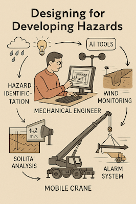
Designing for Developing Hazards: Lessons from the Derrimut Crane Collapse

Designing for Developing Hazards

Crane accidents are among the most visible reminders of the risks inherent in construction. The collapse of a crane at a data centre site in Derrimut, Melbourne, brought attention once again to the vulnerability of temporary lifting structures. While formal investigations are still underway, and no conclusions should be drawn prematurely, the event provides a valuable opportunity for reflection within the engineering community.

This article considers the collapse not as an isolated failure but as a case study in hazard identification. In particular, it highlights how mechanical engineers must adapt from a static, design-phase view of risk to a dynamic, real-time approach to hazard monitoring. Wind, soil stability, and load conditions are well-known hazards. But with modern tools โ€” including LiDAR scanning for obstacle detection โ€” engineers can move toward a future where developing hazards are continuously tracked, anticipated, and controlled.

From Hazard Identification to Live Hazard Monitoring

Hazard identification has traditionally been a design-phase process: engineers anticipate risks, apply safety factors, and create conservative margins. This remains essential. Yet the Derrimut collapse illustrates the limits of a static model in a dynamic environment.

Cranes are exposed to evolving hazards:

  • Wind gusts that change minute by minute.
  • Soil stability that shifts with rainfall, excavation, or groundwater.
  • Obstacles such as power lines or nearby structures, which can create cascading risks if struck.
  • Load dynamics, including swinging or sudden movement.

What is needed is a transition from hazard identification to hazard monitoring: a continuous loop where design assumptions are validated against real-time data, and where developing risks are detected before they become failures.

Wind Hazards: Predicting the Unpredictable

Wind is a leading cause of crane collapses. Engineers know the mathematics: pressure rises with the square of velocity. A 50 km/h gust exerts twice the force of a 35 km/h breeze.

Most cranes today are fitted with anemometers and alarms, but these are often basic: a single reading at a single point, with alarms sounding when preset thresholds are exceeded. This approach can miss:

  • Local gust variability along a long jib.
  • Interaction with crane orientation (wind hitting the broadside is more critical than aligned wind).
  • Forecasted conditions that could deteriorate within minutes.

Next-generation wind monitoring could include:

  • Multi-point sensor arrays on cranes.
  • Integration with Bureau of Meteorology gust forecasts.
  • AI models predicting when risk thresholds will be exceeded, not just reporting when they are crossed.
  • Automatic crane repositioning to minimise wind exposure.

This transforms alarms from reactive to predictive โ€” the difference between warning after a hazard is present and anticipating before it materialises.


Soil Hazards: Stability Under Load

Ground conditions are another silent but critical hazard. Outriggers may impose hundreds of kilonewtons on pads, meaning even small soil weaknesses can lead to tilting or overturning.

Engineering practice already includes soil investigations: boreholes, CPT, SPT, and FEA models. But these tests capture conditions before installation, not necessarily during operation. Soil strength can change due to rainfall, groundwater shifts, or nearby excavation.

Live soil monitoring can be achieved with:

  • Load cells under mats to track ground reactions.
  • Settlement gauges to detect tilt.
  • Piezometers for pore pressure during rain events.
  • Integrated warnings when ground resistance trends downward.

This approach acknowledges soil as a living hazard that changes daily.

LiDAR and Obstacle Detection: Power Lines and Proximity Hazards

One striking feature of the Derrimut collapse was the craneโ€™s boom striking power lines. Contact with utilities is a recurrent hazard in crane operations worldwide. While operators are trained to maintain exclusion zones, in practice visibility, fatigue, or unexpected boom movement can still lead to contact.

LiDAR scanning offers a solution.

  • How it works: LiDAR (Light Detection and Ranging) emits laser pulses to map surroundings in 3D with centimetre accuracy. Mounted on a crane, it can create a live digital map of nearby obstacles.
  • Application in cranes:
    • Detecting and mapping power lines, buildings, or scaffolding in the lift path.
    • Setting proximity alarms when a boom, hook, or load approaches a defined clearance.
    • Combining with wind data to predict if gusts could push the load into restricted zones.

In aviation, LiDAR and radar-based systems are standard for obstacle detection. In construction, adoption is patchy. Yet the technology exists, is cost-effective, and could dramatically reduce risks of contact with hazards like live power lines.

LiDARโ€™s strength lies not only in static mapping but in detecting movement โ€” for example, when a suspended load begins to swing toward a power line due to a gust. This is a quintessential developing hazard, one that static design could never fully capture.

Integrated Hazard Dashboards

Wind, soil, and LiDAR obstacle detection all provide valuable data. But their true power lies in integration. Imagine a crane operatorโ€™s cabin equipped with a single dashboard displaying:

  • Wind speeds and gust forecasts, colour-coded for risk.
  • Soil reaction forces under each outrigger, with alerts if settlement is trending.
  • LiDAR mapping of nearby structures and power lines, with real-time clearance zones.
  • Predictive risk models showing probability of instability or contact over the next 30 minutes.

This integration mirrors aviationโ€™s cockpit: multiple inputs fused into actionable guidance. For cranes, such systems could shift the operatorโ€™s role from reactive decision-maker to proactive risk manager.


AI as a Predictive Partner

Artificial Intelligence has a natural role in hazard monitoring:

  • Sensor fusion: combining wind, soil, and LiDAR inputs into coherent risk profiles.
  • Prediction: learning from past crane incidents to forecast when risks are likely to escalate.
  • Decision support: providing operators with clear options (โ€œsafe to continue lift for 20 minutesโ€ / โ€œhalt operations โ€” clearance margin < 1mโ€).

The challenge is balance. AI should not replace human oversight, but augment it. Over-reliance could create new vulnerabilities if operators become complacent. The design challenge is to build AI into systems that support human judgment rather than substitute for it.


Ethics and Engineering Responsibility

The Derrimut collapse underscores the ethical responsibility of mechanical engineers. Hazard identification is not just a design requirement; it is a matter of public safety. The profession has a duty to anticipate, detect, and control risks wherever possible.

The tools now exist to monitor developing hazards โ€” wind sensors, soil gauges, LiDAR scanners, and AI dashboards. If lives and infrastructure can be protected through wider adoption of these tools, then the question becomes one of responsibility: should they be optional, or mandatory?

Open Questions for the Future

  1. Would integrated live monitoring have reduced the risks at Derrimut?
  2. Should all cranes be fitted with LiDAR obstacle detection as standard?
  3. Do we already have enough technology, but lack regulation and enforcement?
  4. What role should AI play in balancing predictive insight with operator autonomy?

The Derrimut incident remains under investigation. No conclusions can be drawn about its specific cause until findings are published. Yet as a case study, it illustrates the broader point that hazards in crane operations are dynamic. Wind, soil, obstacles, and loads evolve minute by minute.

Mechanical engineers have the tools โ€” wind sensors, soil monitors, LiDAR scanners, integrated dashboards, and AI โ€” to detect these developing hazards. The challenge is to move from a culture of static design assumptions to one of continuous hazard monitoring.

The ultimate professional question is this: If aviation can integrate multiple systems to monitor and predict hazards, why canโ€™t construction do the same for cranes? And if we can, how soon will we accept the ethical responsibility to make it standard?

References and Further Reading

  • ISO 4301 / AS 1418 โ€” Crane standards covering stability and wind.
  • ISO 12480-1:2003 โ€” Safe use of cranes; includes environmental hazard monitoring.
  • WorkSafe Victoria Guidance Notes โ€” Crane safety management.
  • Holickรฝ & Retief (2017) โ€” Probabilistic treatment of wind action in structural design.
  • Nguyen et al. (2020) โ€” Real-time monitoring of crane foundation response under variable soil conditions.
  • Liebherr LICCON โ€” Example of integrated load and geometry monitoring.
  • FAA LLWAS โ€” Aviationโ€™s real-time wind shear alert system, model for construction.
  • Recent research in LiDAR obstacle detection (e.g., IEEE Transactions on Intelligent Transportation Systems) โ€” showing LiDARโ€™s potential in complex environments.
Hamilton By Design logo displayed on a blue tilted rectangle with a grey gradient background
3D LiDAR scanning and 3D modelling service button โ€” laser scanner capturing a point cloud for engineering and CAD modelling
Mechanical engineering services

Our clients:

Name
Would you like us to arrange a phone consultation for you?
Address

Structural Drafting

3D CAD Modelling Australia service banner for Hamilton By Design
Australian Drafting logo featuring bold white text reading "Australian Drafting" centred on a blue rounded rectangle background.
Engineering Governance title graphic featuring bold white text reading "Engineering Governance" centred on a blue rounded rectangle background.
Mechanical, Structural & Pipework Drafting service banner by Hamilton By Design featuring white text on a blue background.
Mechanical engineering services
Blue rounded button with the text โ€œSolidWorks Designโ€ in white.
Finite Element Analysis (FEA) engineering simulation button
3D LiDAR Scanning Darwin for engineering surveys, laser scanning, reality capture and point cloud modelling services
3D LiDAR Scanning Australia engineering services for laser scanning, reality capture, scan-to-CAD, Scan-to-BIM and as-built documentation across Australia
3D LiDAR scanning services on the Central Coast providing engineering-grade laser scanning, point cloud capture, scan-to-CAD modelling and industrial reality capture for infrastructure and industrial projects.
3D LiDAR Scanning Perth for engineering surveys, laser scanning, reality capture and point cloud modelling services
3D LiDAR Scanning Sydney for engineering surveys, laser scanning, reality capture and point cloud modelling services
3D LiDAR Scanning Brisbane for engineering surveys, laser scanning, reality capture and point cloud modelling services
3D LiDAR Scanning Canberra for engineering surveys, laser scanning, reality capture and point cloud modelling services
3D LiDAR Scanning Newcastle for engineering surveys, laser scanning, reality capture and point cloud modelling services
3D LiDAR Scanning Adelaide for engineering surveys, laser scanning, reality capture and point cloud modelling services

Mechanical Drafting

3D Laser Scanning

Mechanical Engineering

Consulting Engineers