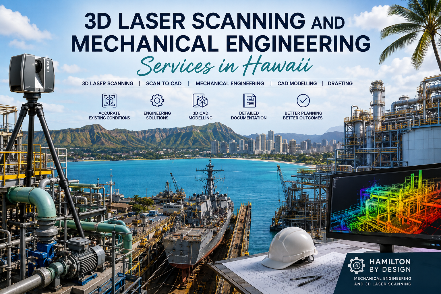
3D Laser Scanning and Mechanical Engineering Services in Hawaii
Hamilton By Design provides engineer-led 3D laser scanning, LiDAR reality capture, mechanical engineering, 3D CAD modelling and drafting support for industrial, marine, infrastructure and commercial projects in Hawaii.
Our integrated approach connects accurate existing-condition capture with practical engineering development.
Rather than providing a point cloud as an isolated deliverable, we can use captured site information to support equipment modifications, brownfield upgrades, mechanical layouts, reverse engineering, clash reviews, installation planning and fabrication documentation.
Services can be scoped for projects across Oʻahu, Maui, Hawaiʻi Island, Kauaʻi and other accessible locations throughout the Hawaiian Islands.
Engineering-Grade 3D Laser Scanning in Hawaii
Existing drawings are not always sufficiently accurate for plant modifications, equipment replacement or retrofit projects.
Buildings, machinery, services and structures may have been altered without the original drawings being updated. This creates uncertainty during design and increases the risk of clashes, fabrication changes and installation delays.
Hamilton By Design uses terrestrial LiDAR scanning to capture measurable existing conditions.
A registered point cloud can document visible features such as:
- industrial machinery
- marine equipment
- structural steel
- pipework
- tanks and vessels
- conveyors
- platforms and stairs
- plant rooms
- building interiors
- overhead services
- ports and waterfront infrastructure
- manufacturing equipment
- utilities and service corridors
The captured information can provide an accurate spatial reference for engineering, modelling, planning and documentation.
Learn more about our engineering-grade 3D laser scanning services.
Mechanical Engineering Support for Existing Facilities
Mechanical engineering projects in operating facilities often involve working around existing machinery, structures, services and access restrictions.
Hamilton By Design can use measured site information to support:
- equipment replacement
- machinery relocation
- plant modifications
- mechanical layouts
- maintenance-access improvements
- conveyor and chute upgrades
- pump and pipework arrangements
- tank and vessel modifications
- access-platform development
- machine guarding
- reverse engineering
- fabrication planning
- shutdown preparation
- installation sequencing
The engineering scope can be developed incrementally, beginning with site capture and progressing through modelling, concept development and detailed documentation.
Explore our broader mechanical and digital engineering services.
Scan-to-CAD Modelling
A point cloud provides a detailed record of the visible environment, but it may not be the final deliverable required by the project team.
Hamilton By Design can convert selected point-cloud information into practical CAD geometry.
Depending on the project, Scan-to-CAD outputs may include:
- existing-condition 3D models
- machinery envelopes
- structural reference models
- equipment arrangements
- general arrangement drawings
- floor plans
- elevations and sections
- pipe and service routes
- installation interfaces
- fabrication reference geometry
- clash-review models
It is not always necessary to model every object captured by the scanner.
The modelling scope can focus on the machinery, structures and services that directly influence the project. The remainder of the point cloud can stay available as a measurable spatial reference.
Learn more about 3D CAD modelling and mechanical drafting.
Industrial and Manufacturing Facilities
Hawaii contains food-production facilities, workshops, warehouses, processing operations, maintenance facilities and other industrial assets that may require accurate existing-condition documentation.
3D laser scanning and mechanical engineering can support:
- factory layout changes
- machinery installations
- production-line modifications
- packaging equipment upgrades
- processing equipment replacement
- equipment relocation
- conveyor installation
- utility coordination
- access and clearance reviews
- brownfield factory upgrades
Proposed machinery can be positioned within the scanned facility to assess fit, maintenance access and surrounding constraints before installation begins.
For projects involving factory and production equipment, see our Manufacturing Layout Design Australia service.
Marine and Ship-Repair Engineering
Marine environments often contain complex arrangements of machinery, structures, pipework, confined spaces and curved surfaces.
3D laser scanning may support marine and ship-repair projects involving:
- vessel machinery spaces
- engine rooms
- deck equipment
- marine pipework
- structural modifications
- equipment replacement
- retrofit projects
- access platforms
- lifting arrangements
- shore-based marine facilities
- shipyard workshops
- dry-dock infrastructure
The registered point cloud can provide a measurable reference for developing equipment layouts, replacement components and installation documentation.
For marine projects, the scope should account for access restrictions, vessel movement, corrosion, confined spaces and the required project coordinate system.
Ports and Waterfront Infrastructure
Hawaii’s island geography places significant importance on ports, harbours and waterfront infrastructure.
Engineering-grade reality capture can support projects involving:
- cargo-handling equipment
- wharf structures
- loading facilities
- conveyors
- access platforms
- maintenance structures
- pipework and services
- warehouses
- terminals
- mechanical equipment
- utility upgrades
- equipment replacement
LiDAR scanning can document existing conditions before maintenance, refurbishment or equipment installation work begins.
The captured information may also support contractor coordination, fabrication planning, as-built documentation and future asset-management requirements.
Energy and Utility Infrastructure
Reliable energy, water and utility infrastructure is particularly important in island environments.
Hamilton By Design can support existing-condition capture and mechanical documentation for:
- power-generation facilities
- pump stations
- water-treatment assets
- wastewater facilities
- pipework systems
- tanks
- plant rooms
- mechanical equipment
- utility corridors
- renewable-energy infrastructure
- backup-generation equipment
- cooling and ventilation systems
3D scanning can be valuable where plant areas are congested or where existing drawings do not accurately represent the installed condition.
Food and Beverage Production
Food and beverage facilities can include tightly coordinated machinery, conveyors, packaging lines, tanks, pipework and washdown services.
Manufacturing-layout and scanning services may support:
- production-line rearrangements
- packaging equipment installations
- conveyor modifications
- tank and vessel replacement
- pipework coordination
- hygienic access planning
- washdown-area documentation
- drainage coordination
- maintenance-clearance reviews
- equipment-removal planning
Accurate site capture can help document facilities that have changed progressively through multiple production upgrades.
Hotels, Resorts and Commercial Facilities
Hawaii’s commercial and hospitality facilities may also require accurate existing-condition information for refurbishment and upgrade projects.
Potential applications include:
- plant-room documentation
- mechanical-services coordination
- back-of-house facilities
- kitchen and laundry equipment layouts
- utility upgrades
- retail and tenancy modifications
- structural interfaces
- refurbishment planning
- existing-condition floor plans
- Scan-to-BIM documentation
Scanning can reduce reliance on incomplete plans and provide designers with a measurable reference before demolition or new installation work begins.
Brownfield Engineering and Retrofit Projects
Brownfield projects involve modifying an existing operating asset.
These projects can be challenging because the proposed design must fit around existing machinery, structural elements, services and operational constraints.
A scan-led engineering workflow can help identify:
- structural clashes
- equipment conflicts
- restricted access
- inadequate maintenance clearances
- installation constraints
- service-routing conflicts
- difficult lifting requirements
- incomplete drawing information
Identifying these issues during design can reduce uncertainty during fabrication and installation.
Typical applications include:
- plant upgrades
- machinery replacement
- retrofit components
- access improvements
- piping modifications
- conveyor changes
- equipment relocation
- structural interfaces
- shutdown work
- refurbishment projects
Reverse Engineering
Replacement parts and legacy equipment are not always supported by reliable drawings or original manufacturer information.
Hamilton By Design can use scanning, site measurements and CAD modelling to support reverse engineering of:
- machinery components
- guards and covers
- housings
- frames
- brackets
- equipment interfaces
- pipework
- structural connections
- obsolete parts
- custom retrofit components
The required level of accuracy depends on the function of the component, manufacturing method and available access.
Reverse-engineering work should begin with a clear definition of the required output, tolerances and intended manufacturing process.
Mechanical and Structural Drafting
Point-cloud information and engineering concepts can be developed into coordinated drawings.
Typical drafting outputs may include:
- general arrangement drawings
- equipment layouts
- fabrication drawings
- installation drawings
- sections and elevations
- assembly drawings
- detail drawings
- structural-steel details
- access-platform drawings
- machine-guarding drawings
- pipe-support arrangements
- bills of materials
Available formats may include DWG, DXF and PDF, together with suitable 3D model formats.
Deliverable Formats
Project deliverables can be selected according to the client’s software, contractor requirements and intended use.
Point-cloud formats may include:
- E57
- RCP
- RCS
- LAS
- registered scan projects
CAD and model formats may include:
- STEP
- SAT
- Parasolid
- SolidWorks
- Autodesk Inventor
- DWG
- DXF
- Navisworks-compatible models
- PDF drawing packages
The required coordinate system, file structure, modelling detail and drawing standards should be agreed before site capture begins.
Clash Detection and Constructability Reviews
Proposed equipment and supplier models can be positioned within the scanned environment to identify potential conflicts.
A coordination review may assess:
- machinery fit
- structural clearances
- pipework clashes
- overhead services
- access requirements
- installation paths
- maintenance zones
- lifting arrangements
- equipment-removal envelopes
- contractor work areas
This process can support design reviews before equipment is fabricated, shipped or installed.
For island projects, reviewing equipment fit before shipment may be particularly valuable because late changes can increase freight, mobilisation and installation costs.
Shutdown and Installation Planning
Industrial shutdowns often require significant work to be completed within a limited period.
3D scanning and coordinated modelling may support:
- shutdown work packs
- equipment-removal planning
- lifting studies
- temporary access planning
- installation sequencing
- clash reviews
- prefabrication
- contractor coordination
- dimensional verification
- post-installation as-built capture
Capturing accurate existing conditions before the shutdown can allow more engineering and fabrication work to be completed offsite.
A Staged Project Process
Hamilton By Design can deliver Hawaii projects through a staged process.
Stage 1 — Project definition
The site, asset, intended modification and required deliverables are reviewed.
Stage 2 — Existing-information review
Available drawings, photographs, supplier models and specifications are assessed.
Stage 3 — Site mobilisation and scanning
The relevant facility, equipment or structure is captured using appropriate scanning methods.
Stage 4 — Point-cloud registration
Individual scans are combined into a coordinated dataset.
Stage 5 — Existing-condition review
The point cloud is checked against the project requirements and modelling scope.
Stage 6 — CAD modelling
Selected machinery, structures and services are converted into usable engineering geometry.
Stage 7 — Engineering development
Proposed modifications, equipment arrangements or replacement components are developed.
Stage 8 — Coordination and review
Clashes, access requirements, interfaces and installation constraints are assessed.
Stage 9 — Drawings and deliverables
The agreed models, drawings and point-cloud files are issued.
Stage 10 — Installation or as-built support
Additional verification, site support or final-condition capture can be completed where required.
Project Planning for Hawaii
Hawaii projects require careful planning because mobilisation, freight, inter-island travel, site access and equipment transport can influence the project scope.
Before mobilisation, Hamilton By Design would normally confirm:
- island and site location
- required inductions
- security requirements
- available access hours
- scanner transport arrangements
- inter-island travel requirements
- shutdown or operating restrictions
- local site support
- required coordinate system
- required deliverables
- applicable standards and approval requirements
Where practical, project information can be reviewed remotely before site attendance so the scanning and engineering scope is clearly defined.
Engineering Standards and Local Requirements
Projects in Hawaii may be governed by United States federal, state, county, client or facility-specific requirements.
Applicable standards should be confirmed at the beginning of the project.
Depending on the work, requirements may involve:
- occupational health and safety
- building and structural codes
- mechanical systems
- machine safety
- marine requirements
- electrical clearances
- fire and life-safety provisions
- environmental approvals
- port or defence-site requirements
- professional engineering registration
Hamilton By Design can provide scanning, modelling, drafting and engineering-support services within an agreed scope. Where local professional certification or statutory approval is required, the project may also need review by an appropriately licensed Hawaii or United States professional.
Areas That May Be Supported
Subject to project scope, travel and site-access requirements, services may be provided for projects on:
- Oʻahu
- Honolulu
- Pearl Harbor
- Kapolei
- Kalaeloa
- Campbell Industrial Park
- Maui
- Kahului
- Hawaiʻi Island
- Hilo
- Kailua-Kona
- Kauaʻi
- Līhuʻe
- other accessible Hawaiian locations
Regional and inter-island projects can be considered where the required mobilisation is commercially practical.
Why Use an Engineer-Led Scanning Service?
A scanning provider may capture the site, but engineering projects normally require more than a visual point cloud.
Hamilton By Design combines:
- mechanical engineering
- trade and fabrication experience
- terrestrial LiDAR scanning
- point-cloud registration
- reverse engineering
- 3D CAD modelling
- mechanical drafting
- structural drafting
- installation planning
This integrated approach helps turn measured site information into practical engineering outputs.
Discuss a Hawaii Project
Hamilton By Design can assist with 3D laser scanning, Scan-to-CAD modelling, mechanical engineering, reverse engineering and drafting for industrial, marine, manufacturing, infrastructure and commercial projects in Hawaii.
To establish an appropriate scope, provide:
- the island and site location
- a description of the asset
- available drawings or photographs
- the intended modification
- required model and drawing formats
- access or security restrictions
- the preferred project timing

Contact Us – Talk To Us
Our clients:

























Related 3D Scanning, Engineering and Industrial Services
Explore additional Hamilton By Design services covering engineering-grade LiDAR scanning, Scan-to-CAD, mechanical engineering, manufacturing, ports, marine infrastructure and remote industrial projects.
Engineering-Grade 3D Laser Scanning
Accurate LiDAR capture and design-ready point-cloud information for industrial, infrastructure and brownfield engineering projects.
View engineering-grade scanning →3D Laser Scanning Services
Terrestrial laser scanning for machinery, structures, buildings, industrial facilities and existing-condition documentation.
Explore 3D laser scanning →Industrial 3D Scanning Services
Reality capture for factories, process plants, machinery, utilities and congested industrial facilities.
View industrial scanning →3D Laser Scanning Across Australia
Mobile scanning support for metropolitan, regional, remote, coastal and industrial engineering projects.
Explore mobile scanning services →3D Scanning Service Locations
An overview of Hamilton By Design scanning, engineering, modelling and drafting service locations.
View service locations →Point Cloud to CAD Australia
Conversion of measured LiDAR point clouds into practical CAD geometry, layouts and engineering models.
Explore Point Cloud to CAD →Point Cloud to AutoCAD
AutoCAD models, existing-condition plans and engineering drawings developed from registered point-cloud data.
View Point Cloud to AutoCAD →Scan to CAD Sydney
Engineering-led Scan-to-CAD modelling for industrial facilities, machinery, structures and brownfield projects.
Explore Scan to CAD Sydney →Scan to CAD Brisbane
LiDAR capture and CAD modelling for industrial equipment, structures, fabrication and installation planning.
Explore Scan to CAD Brisbane →Scan to CAD Perth
Point-cloud conversion for machinery, processing plants, fabrication workshops and mining-support facilities.
Explore Scan to CAD Perth →Scan to BIM Services
Reality capture and coordinated BIM modelling for existing facilities, infrastructure and building upgrade projects.
View Scan to BIM services →Scan to BIM Australia
Engineering-led point-cloud processing and BIM development for industrial, commercial and infrastructure assets.
Explore Scan to BIM Australia →Mechanical and Digital Engineering Services
Integrated mechanical engineering, LiDAR scanning, CAD modelling, drafting and engineering assessment services.
View engineering services →SolidWorks Engineering and Drafting
SolidWorks assemblies, equipment models, mechanical drawings and fabrication-ready engineering documentation.
Explore SolidWorks services →Structural Drafting Australia
Structural layouts, steelwork details and fabrication drawings developed from engineering and point-cloud information.
View structural drafting →Manufacturing and Production Services
Engineering support for operating plants, production equipment, factory modifications and industrial upgrades.
Explore manufacturing services →Manufacturing Layout Design Australia
Factory layouts, production-line planning, machinery arrangements and brownfield facility coordination.
View manufacturing layout design →Reverse Engineering with 3D Scanning
Measured capture and CAD reconstruction of existing machinery, components, interfaces and legacy equipment.
Explore reverse engineering →Scan-to-CAD for Fabrication Drawings
Converting existing physical components into coordinated CAD models and fabrication-ready engineering drawings.
Read about Scan-to-CAD fabrication →Sydney Port Asset Capture Services
LiDAR capture of port infrastructure, mechanical assets, steelwork and waterfront facilities.
View port asset capture →3D LiDAR Scanning for Ports
Engineering-ready scanning and Scan-to-CAD support for port, terminal and cargo-handling infrastructure.
Explore port LiDAR scanning →Port Botany 3D Scanning Services
Reality capture for terminals, logistics facilities, industrial infrastructure and port equipment.
View Port Botany scanning →Brownfield Port Engineering
Mechanical engineering and reality capture for modifications within active port and waterfront facilities.
Explore brownfield port engineering →Port Shutdown Engineering Support
Scanning, modelling and engineering documentation for shutdown-critical port maintenance and upgrade work.
View shutdown engineering →Port of Brisbane Engineering and Scanning
Mechanical engineering and LiDAR scanning for port machinery, infrastructure and brownfield upgrades.
Explore Port of Brisbane services →Mechanical Engineering Port of Newcastle
Mechanical engineering, reverse engineering and scanning for port and bulk-handling equipment.
View port mechanical engineering →3D Engineering Scanning Fiji
Remote-island reality capture providing engineering teams with accurate and measurable site information.
Explore Fiji engineering scanning →3D Laser Scanning New Caledonia
Engineering-grade scanning for remote processing plants, ports, utilities and industrial infrastructure.
View New Caledonia scanning →3D LiDAR Scanning Perth
Reality capture for fabrication workshops, process plants, industrial facilities and remote projects.
Explore Perth LiDAR scanning →3D Laser Scanning in the Pilbara
Remote scanning for industrial plants, conveyors, shutdowns, terminals and heavy infrastructure.
View Pilbara scanning services →