Mining Equipment Reverse Engineering in Carole Park: From Existing Machinery to Reliable Engineering Data

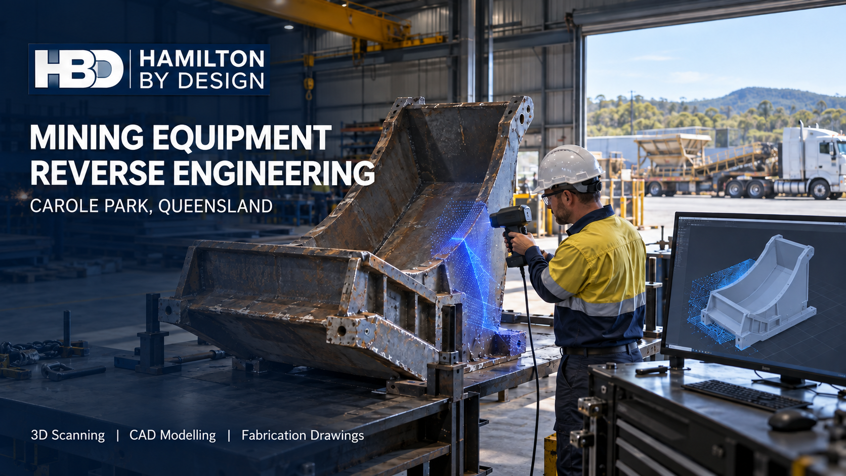
Hamilton By Design hero image for mining equipment reverse engineering in Carole Park, showing an engineer scanning a worn conveyor chute beside its 3D CAD model.
Blue 3D LiDAR scanner icon on a tripod with scanning waves

Carole Park is a practical place to solve difficult equipment problems. Within this industrial suburb in the City of Ipswich, businesses machine components, fabricate steelwork, manufacture wear-protection products and move goods across South East Queensland. Its position beside Brisbaneโ€™s western industrial corridor also gives workshops access to suppliers and transport routes. For a mining-equipment owner, that combination can make Carole Park a useful place to repair, modify or manufacture a component.

However, manufacturing capability is only part of the job. Before a workshop cuts plate or machines a replacement part, someone must establish what the existing equipment actually looks like, which dimensions matter and how the new component will fit. That becomes difficult when the original drawings are missing, the equipment has been modified or years of wear have changed its shape.

Hamilton By Design helps close that information gap through 3D scanning, reverse engineering, mechanical design and drafting. The objective is to turn an existing component or plant area into engineering data that can be checked, discussed and used for the next decision. Our broader approach to reverse engineering mining and industrial equipment starts with the assetโ€™s function and condition, rather than assuming that a digital copy of its present shape is the right replacement.

Why Carole Park calls for a workshop-focused approach

Carole Park has a distinct industrial character. TNN Engineering describes CNC machining and fabrication work for sectors including mining and civil construction. OZQ Engineering lists fabrication, machining and resources-sector work. Wearmin operates in hose and wear protection for demanding industrial applications. These examples show the range of work carried out locally; they do not imply that the companies are Hamilton By Design clients.

That local mix suggests a particular need: engineering information that survives the handover between an equipment owner, a designer and a manufacturer. A worn chute liner may be easy to remove but difficult to define. A machined component may look straightforward until its bolt pattern, shaft fit or installed clearance is measured. A workshop may be able to fabricate an assembly quickly, yet still need reliable information about the plant it must fit.

Reverse engineering is most useful when it addresses those questions before manufacture begins. It can also reveal where the original equipment could be improved, provided the operating conditions, materials, loads and failure history are understood. Reproducing a failed detail without examining why it failed may simply repeat the problem.

Begin with the decision the scan must support

โ€œScan the equipmentโ€ is a starting request, not a complete scope. The right measurement method depends on what the client needs to decide.

If the aim is to relocate a conveyor or fit a new chute, a site scan can capture surrounding steelwork, walkways, pipework and other physical interfaces. If the aim is to manufacture a replacement component, closer measurement of mating surfaces, holes and critical features may be necessary. If the concern is wear, the task may involve comparing the present geometry with a nominal model or agreed reference dimensions.

Hamilton By Design uses 3D scanning and reverse engineering to develop models that serve a defined engineering purpose. The scope should identify the required deliverables, the dimensions that need direct verification and any surfaces that cannot be measured reliably while the equipment is installed.

A scan records visible geometry at a particular time. It does not, by itself, establish the original unworn profile, the material grade or every manufacturing tolerance. Where those details matter, HBD can identify the additional measurements, records or engineering assessment needed.

Replacement-component CAD for mining equipment

Mining and heavy-industrial equipment often remains in service long after its original documentation has become difficult to find. Components may have been repaired, adjusted or made locally over several decades. A replacement therefore needs to be understood in relation to the equipment around it.

For a component brought into a Carole Park workshop, the process might begin with a mesh or measured profile. The model is then developed around functional features: mounting faces, shaft centres, bolt-hole positions, contact surfaces and the space needed for installation. Where wear has distorted a surface, the model should distinguish measured condition from proposed replacement geometry.

Depending on the job, the outputs may include an editable CAD model, a dimensional report, a general arrangement, a fabrication drawing or a file suitable for manufacturing review. The required accuracy should be set by the componentโ€™s function. A broad clearance envelope and a precision-machined fit call for different verification methods.

Keeping the approved model and drawing revision also has value beyond the first replacement. The next maintenance team can begin with an identified design record rather than repeating the entire measurement exercise.

Chutes, conveyors and wear parts

A transfer chute is more than a collection of folded plates. Its performance depends on material flow, wear, access for maintenance and the position of the conveyor equipment around it. A replacement made from an old drawing can create problems if the supporting structure or adjoining plant has changed since that drawing was issued.

For these projects, HBD can capture the installed equipment, model the available space and develop chute or conveyor modifications in CAD. The model allows the team to inspect interfaces and discuss how a proposed assembly will be fabricated, transported and installed. HBDโ€™s mechanical engineering work for mining infrastructure includes materials-handling equipment, transfer stations and plant upgrades.

Wear-part modelling can follow a similar path. A liner or replaceable plate needs geometry that fits the parent equipment, appropriate attachment details and a practical removal path. Recording its geometry and manufacturing revision helps an owner compare later replacements and document changes made in response to wear.

Engineering review should be matched to the proposed change. A new liner profile, altered chute support or conveyor modification may raise different questions about loads, maintenance access and machine safety.

From Carole Park workshop to operating plant

Some assemblies are built in Carole Park but installed at a mine or processing facility elsewhere. In that situation, the workshop and site must share a reliable description of the existing conditions. Even a well-made assembly can be difficult to install if a support is out of position or the available lifting space was assumed rather than measured.

HBDโ€™s scan-to-CAD workflow for Brisbane and Queensland projects brings existing-condition data into a model that can be used to review proposed work. A coordinated model may expose a clash before fabrication, show where another site measurement is needed or help the team plan an installation sequence.

The useful deliverable is not always a complete model of the entire facility. For a specific replacement, it may be enough to capture the assemblyโ€™s mounting points, adjacent obstructions and removal path. Defining that boundary early keeps the survey focused on the decision it needs to support.

Safety and access are part of the design

Mining equipment modifications can affect people who operate, clean and maintain the plant. A new guard may restrict access to a wear part. A relocated chute may change how a blockage is cleared. A revised conveyor arrangement may create a new point where moving components can be reached.

Queensland WorkSafe has documented serious conveyor incidents and emphasises guarding, isolation and risk controls for plant work. HBD can assist by measuring existing arrangements, modelling proposed guards and access changes, and preparing drawings for review within the clientโ€™s risk-management process. The assessment must consider the actual tasks people perform, including maintenance and abnormal conditions, rather than only normal operation.

Relevant references may include the AS/NZS 4024 machinery-safety series and AS/NZS 4024.3610:2015 for conveyor-system safety. AS 1657:2018 may apply when a project includes fixed walkways, platforms, stairs or ladders. The applicable requirements depend on the equipment and the proposed scope; listing a standard on a drawing is not a substitute for assessing the design against it.

A useful record for future repairs

A good reverse-engineering project should leave the owner better informed about the asset. Subject to the clientโ€™s agreed data arrangements, HBD can retain equipment point clouds, component meshes, CAD models, wear-part geometry, dimensional reports, fabrication drawings and manufacturing revisions.

Those records can help distinguish an approved design from an earlier workshop modification. They also give a future maintenance team a starting point when a part wears again or a similar asset needs attention. The value lies in knowing what was measured, what was inferred, what was changed and which revision was manufactured.

Frequently asked questions

Can you reverse engineer a worn mining-equipment component?

Yes, although the worn surface should not automatically become the replacement shape. HBD can scan or measure the component, identify critical interfaces and develop proposed CAD geometry. The ownerโ€™s operating records, comparable parts and engineering review may be needed to establish the intended profile.

Is 3D laser scanning accurate enough to manufacture a replacement part?

That depends on the size of the part and the tolerances that matter. A site scan can be highly useful for overall geometry, clearances and installation interfaces. Precision fits, small holes or machined surfaces may require closer-range measurement or direct dimensional verification. The measurement plan should be agreed before scanning.

Can a component be scanned in a Carole Park workshop and fitted at a remote mine?

Potentially. The workshop component and its installed interfaces must both be understood. For a critical fit, HBD can define which site dimensions, mounting features and surrounding clearances need to be captured before the replacement is finalised.

Do you provide fabrication drawings as well as a 3D model?

Yes, when fabrication documentation is included in the agreed scope. A 3D model, a general arrangement and a fabrication drawing serve different purposes. The drawing package should identify the details the manufacturer needs, along with the applicable revision and any dimensions requiring confirmation.

Can you help improve a chute rather than reproduce it exactly?

Yes. HBD can document the existing chute and develop a revised mechanical arrangement for review. An improvement should be based on the material handled, observed wear or blockage, available space, support conditions and maintenance needs. Additional analysis or specialist input may be required for particular changes.

Which Australian standards apply?

The answer depends on the equipment and work being undertaken. Machinery guarding and risk reduction may call for parts of AS/NZS 4024; conveyor modifications may involve AS/NZS 4024.3610; fixed access may involve AS 1657. Steelwork associated with mechanical equipment may call for AS 3990, where its scope applies. The relevant standards are selected for the actual design, not applied as a generic list.

Discuss a component or plant upgrade

If an equipment part has no reliable drawing, a chute needs modification or a new assembly must fit existing plant, Hamilton By Design can help define the measurement and engineering work required. Send through photographs, available drawings, the equipment location and a brief description of the problem. We can then discuss what needs to be captured, what must be verified and which deliverables will help you move toward manufacture or installation.


Hamilton By Design logo displayed on a blue tilted rectangle with a grey gradient background

Contact Us – Talk To Us

Name
Would you like us to arrange a phone consultation for you?
Address

Our clients:


Industrial 3D Laser Scanning in Geebung, Virginia and Northgate: Engineering Brisbane Northโ€™s Established Manufacturing Corridor

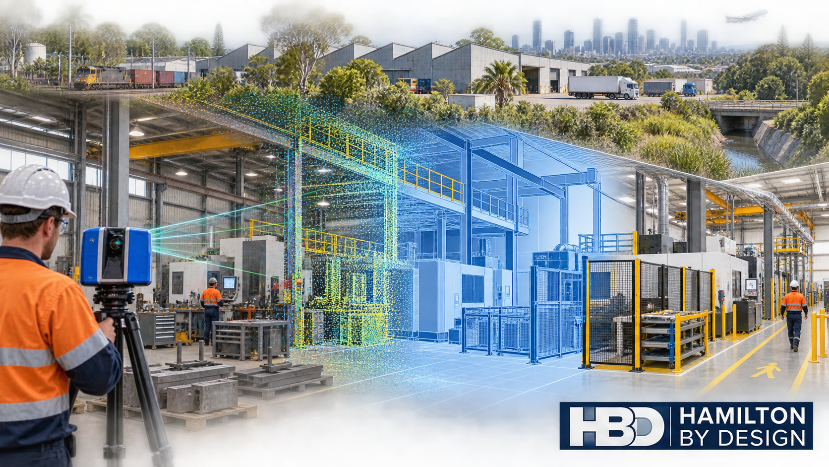
Industrial 3D laser scanning of a Brisbane north factory transitioning from point-cloud data to an engineered CAD model.
Blue 3D LiDAR scanner icon on a tripod with scanning waves

Geebung, Virginia and Northgate form one of Brisbaneโ€™s most established manufacturing and engineering corridors. Located approximately 10 to 14 kilometres north of the Brisbane CBD, these suburbs support a diverse industrial community encompassing precision machining, sheet-metal fabrication, specialist machinery manufacture, hydraulic equipment, industrial maintenance, warehousing and freight distribution.

Unlike a newly developed industrial estate, Brisbaneโ€™s northern corridor has evolved over decades. Older workshops sit alongside advanced manufacturing businesses and modern logistics facilities. Many properties have been extended, subdivided or adapted to accommodate machinery and production processes that were never anticipated when the buildings were first constructed.

This mixture creates a distinctive engineering environment. The challenge is rarely limited to designing a new machine or component. Businesses must determine how new equipment will fit within an existing factory, how it will interact with surrounding structures and services, and how it can be installed without introducing safety, access or maintenance problems.

Hamilton By Design assists manufacturers, fabricators and industrial operators through engineering-led 3D scanning services in Brisbane, reverse engineering, mechanical design, scan-to-CAD modelling, industrial drafting and as-built verification.

A manufacturing corridor with practical capability

Geebung, Virginia and Northgate should not be regarded simply as a warehouse district. The corridor contains a significant concentration of businesses involved in making, repairing and improving industrial equipment.

Local capabilities include CNC machining, aluminium casting, metal fabrication, hydraulics, special-purpose machinery, mining equipment, oil-and-gas components, material handling and equipment servicing. These operations are supported by logistics businesses, industrial suppliers, warehousing facilities and access to the broader Brisbane engineering workforce.

The corridorโ€™s location is an important part of its industrial character. Businesses have access to Sandgate Road, Gympie Road and the Gateway Motorway, with practical connections to Brisbane Airport, the Port of Brisbane and the wider South East Queensland freight network.

However, good regional access does not automatically mean that an industrial site is easy to modify. Inside individual properties, engineering teams may encounter narrow driveways, shared yards, limited truck-turning space, closely spaced buildings, congested loading areas and restricted installation routes.

These local conditions make reliable existing-site information particularly valuable.

Why existing drawings may not represent the factory today

Many industrial buildings in Geebung, Virginia and Northgate have been occupied and modified by several businesses during their working lives. Machinery may have been installed, relocated or removed. Platforms may have been extended, guards replaced, services rerouted and storage areas progressively expanded.

Original architectural drawings may still be useful, but they often do not show the current operating arrangement. Even relatively recent drawings may omit smaller modifications made during maintenance work or production changes.

This can create uncertainty when planning:

  • New manufacturing cells
  • CNC machinery installations
  • Conveyor modifications
  • Robotic equipment
  • Guarding upgrades
  • Storage and materials-handling systems
  • Pipework and ducting
  • Access platforms
  • Loading-area changes
  • Machinery relocations

Conventional tape measurements can capture individual dimensions, but they may not adequately record the relationships between machinery, columns, roof framing, services, access routes and neighbouring equipment.

Engineering-grade LiDAR scanning addresses this problem by capturing the visible facility as a coordinated three-dimensional dataset. The resulting point cloud provides a measurable record of the factory at the time of scanning.

From factory scan to usable engineering information

A point cloud is valuable, but it is not automatically an engineering solution. Its real value emerges when the captured information is interpreted and converted into suitable design deliverables.

Hamilton By Designโ€™s process can include site planning, LiDAR capture, scan registration, quality review, point-cloud preparation, CAD modelling, mechanical design and drawing production.

Depending on the purpose of the project, deliverables may include:

  • Registered E57, RCP or LAS point-cloud files
  • Two-dimensional factory layouts
  • Three-dimensional equipment and building models
  • Machinery location plans
  • General arrangement drawings
  • Equipment-clearance studies
  • Clash-detection models
  • Fabrication drawings
  • Installation reference information
  • As-built records

The required level of modelling should be selected according to the intended use. A machinery-relocation study may require accurate equipment envelopes, column locations, access routes and overhead clearances. It may not require every wall, pipe or small building feature to be modelled.

Defining this purpose before scanning helps control cost while ensuring that the information is sufficiently detailed for the decisions being made.

Supporting machinery relocation and factory upgrades

Machinery relocation involves more than checking whether a machine fits inside an available rectangle on a floor plan.

The proposed arrangement may need to account for:

  • Operator access
  • Raw-material delivery
  • Finished-product removal
  • Maintenance clearances
  • Electrical and hydraulic connections
  • Extraction or ventilation services
  • Overhead crane access
  • Forklift routes
  • Guard opening distances
  • Emergency access
  • Installation and lifting space

A three-dimensional model allows these relationships to be reviewed before equipment is disconnected or foundations are constructed.

For factories with limited shutdown windows, this is especially important. Discovering a clash during installation can extend downtime, create urgent fabrication work and delay the return to production. Capturing the existing environment early allows more of the uncertainty to be resolved during design.

Hamilton By Design can combine measured site information with scan-to-CAD reverse engineering and fabrication drawings to support the project from initial site capture through to practical installation information.

Reverse engineering for Brisbane north manufacturers

The corridorโ€™s concentration of long-established machinery creates another common problem: equipment may remain operational long after its original drawings or OEM support have disappeared.

A damaged or worn component cannot always be reproduced reliably from a few manual measurements. Its geometry may incorporate complex curves, fabricated transitions, cast surfaces, machining features or interfaces with surrounding equipment.

Hamilton By Designโ€™s reverse-engineer 3D scanning service can capture the physical component and surrounding interfaces before developing editable CAD information.

The engineering process must distinguish among:

  • Original design geometry
  • Normal manufacturing variation
  • Operational wear
  • Permanent distortion
  • Previous repairs
  • Material build-up
  • Intentional site modification
  • Damage or failure

Blindly copying a worn component may reproduce the problem that caused it to fail. Effective reverse engineering therefore requires technical judgement as well as accurate measurement.

Potential applications within the Geebungโ€“Virginiaโ€“Northgate corridor include machine guards, brackets, chutes, hoppers, wear components, hydraulic equipment, shafts, fabricated covers, equipment bases and discontinued replacement parts.

Machinery safety and maintainable access

Manufacturing upgrades can introduce hazards if safety is considered only after the production layout has been finalised.

Machinery may expose workers to:

  • Rotating components
  • Drawing-in points
  • Crushing or shearing zones
  • Unexpected movement
  • Ejected materials
  • Hot surfaces
  • Stored hydraulic or pneumatic energy
  • Restricted isolation points
  • Unsafe cleaning access
  • Falls from elevated work areas

Hamilton By Design can assist by recording the existing arrangement, identifying geometric constraints and developing practical guarding or access modifications. Depending on the equipment and project scope, relevant requirements may include the AS/NZS 4024 safety-of-machinery series and AS 1657 for fixed platforms, walkways, stairs and ladders.

The objective should not be to place an enclosure around a machine without considering how the equipment is operated. A guard that prevents maintenance, obstructs production or is difficult to remove may be bypassed by operators. Effective guarding must balance risk reduction with visibility, access, isolation, cleaning and maintenance requirements.

Consultation with operators and maintainers is therefore an essential part of the design process.

Logistics, forklifts and constrained industrial yards

The corridorโ€™s strong connection to Brisbaneโ€™s freight network creates opportunities for manufacturers and logistics operators, but it also creates risks within individual sites.

Older industrial properties may have been developed before current traffic volumes, vehicle sizes or warehouse practices were anticipated. Forklifts, trucks, pedestrians, loading activities and maintenance work may compete for the same restricted space.

Three-dimensional scanning can support the development of:

  • Loading-area layouts
  • Vehicle-clearance studies
  • Conveyor arrangements
  • Forklift and pedestrian-separation plans
  • Maintenance platforms
  • Storage-equipment layouts
  • Installation sequencing
  • Equipment-relocation studies

HBD can document the physical environment and help develop engineering controls. Operational traffic management, workplace procedures and staff consultation remain essential parts of the broader risk-management process.

A local issue that cannot be ignored: flood exposure

Parts of the greater Virginia and Geebung area are influenced by the Downfall Creek catchment. Flood exposure varies between properties, and businesses should avoid making assumptions based solely on suburb boundaries.

When a flood-affected industrial site is being upgraded, the engineering review may need to consider the location of electrical equipment, stored materials, controls, motors, valuable machinery and critical production assets.

LiDAR scanning does not replace professional flood modelling or survey control where legally defined levels are required. It can, however, create a detailed spatial record of floors, equipment positions, access routes and building features. This information may assist other specialists and the facility owner when considering resilience measures.

For local manufacturers, this is a genuine regional considerationโ€”not a generic statement that applies equally to every industrial suburb.

Preserving industrial knowledge through controlled data

A point cloud and CAD model can remain valuable after the immediate project has finished. When properly managed, the dataset becomes part of the organisationโ€™s engineering knowledge.

Hamilton By Design can retain agreed project information such as:

  • Factory point clouds
  • Machinery scans
  • Equipment layouts
  • Site photographs
  • Replacement-part CAD
  • Guarding surveys
  • Fabrication drawings
  • Design assumptions
  • Issued revisions
  • As-built records

This is particularly useful for businesses that have historically relied on the knowledge of a small number of experienced employees.

When those employees retire or leave, undocumented information about machinery, previous modifications and equipment interfaces can disappear with them. A controlled digital record helps transfer that knowledge into a form that can be reviewed and reused.

Engineering services for Geebung, Virginia and Northgate

Hamilton By Design can support Brisbane north industrial clients with:

  • Workshop and factory scanning
  • Machinery and equipment layouts
  • Brownfield plant-upgrade design
  • Scan-to-CAD modelling
  • Reverse engineering
  • Mechanical design and drafting
  • Machine-guarding modifications
  • Platforms and maintenance access
  • Conveyor and chute modifications
  • Fabrication drawings
  • As-built verification
  • Clash detection
  • Installation planning
  • Engineering-data and revision control

Applicable standards depend on the equipment and project. They may include AS/NZS 4024, AS 1657, AS 4991, AS 3990, AS 4100, AS/NZS 1554, AS 4041, AS 1210 and the AS 1418 and AS 2550 series.

Hamilton By Design provides mechanical engineering and drafting services. Where structural certification, specialised statutory approval or Queensland professional engineering registration is required, the appropriate registered professional must be engaged and involved in accordance with the applicable legislation.

Frequently asked questions

What can be captured during an industrial 3D laser scan?

LiDAR can capture visible factory geometry, including floors, walls, columns, roof structures, machinery, conveyors, platforms, pipework, ducting, loading areas and access routes. Hidden or internal features may require drawings, physical inspection or another measurement method.

Can a factory continue operating while it is scanned?

Often it can. The scanning plan can be arranged around production, vehicle movements and restricted areas. Moving people, forklifts or products may create temporary visual obstructions, so some areas may need to be captured during quieter periods or planned shutdowns.

Can HBD convert a factory scan into a two-dimensional layout?

Yes. Registered point-cloud information can be used to develop equipment layouts, general arrangements, elevations and sections. The required drawing content and accuracy should be agreed before scanning.

Can scanning help determine whether new machinery will fit?

Yes. The proposed machine envelope can be positioned within the existing-condition model to review columns, walls, overhead structures, neighbouring machinery, access paths and maintenance clearances. Service connections and installation requirements must also be considered.

Can worn machinery components be reverse engineered?

Yes, where the available geometry and condition permit. The process should identify wear, damage, distortion and prior repairs rather than automatically reproducing every scanned surface.

Does a point cloud replace engineering design?

No. A point cloud records measured visible geometry. Engineering design is still required to define loads, materials, tolerances, safety requirements, fabrication details and compliance obligations.

Can HBD produce fabrication drawings?

Yes. HBD can develop suitable mechanical and fabrication documentation from verified scan data and approved design information. The precise deliverables depend on the asset, required design responsibility and certification pathway.

Which Australian Standards apply to a factory upgrade?

There is no single standard covering every factory modification. Relevant requirements may include machinery safety, fixed access, lifting equipment, welding, mechanical-equipment steelwork, structural design or pressure equipment standards. The applicable standards should be established during the projectโ€™s scope and risk review.

Can scan data be retained for future projects?

Yes. Agreed point clouds, CAD models, photographs and controlled drawings can be retained as an engineering reference. File ownership, access, formats and retention periods should be documented in the proposal.

Building better upgrades from measured information

Geebung, Virginia and Northgate combine the strengths of an established manufacturing district with the pressures of modern industrial development. Advanced machinery and automated systems must often be fitted into buildings that have already experienced decades of occupation and modification.

In this setting, assumptions carry real consequences. An incorrect dimension can cause a fabricated component not to fit. An incomplete layout can obstruct maintenance. An overlooked access requirement can turn a straightforward installation into an extended shutdown.

Engineering-led 3D scanning provides a reliable starting point by capturing the facility as it exists today. When combined with mechanical design, reverse engineering, drafting and controlled engineering data, it can help Brisbane north manufacturers plan upgrades with greater confidence.

For businesses considering machinery relocation, factory modification, guarding improvements or replacement-component development, Hamilton By Design can provide a connected workflow from site capture through to practical engineering documentation.


Hamilton By Design logo displayed on a blue tilted rectangle with a grey gradient background

Contact Us – Talk To Us

Name
Would you like us to arrange a phone consultation for you?
Address

Our clients:



What the Ambitious Australia Report Means for Australian Manufacturers

Australian industrial innovation pathway showing research, LiDAR scanning, point-cloud capture, CAD engineering, manufacturing and operating infrastructure.
Blue line-art icon showing a lightbulb, mechanical gear, Australian map and factory representing Australian manufacturing research and development.

Australia has strong researchers, capable engineers and experienced manufacturers. However, having these capabilities does not automatically mean that a promising idea will become equipment that can be manufactured, installed, operated and maintained successfully.

The Australian Governmentโ€™s Ambitious Australia: Strategic Examination of Research and Development Final Report examines this gap. Released in March 2026, the report contains 20 recommendations focused on improving Australiaโ€™s research, development and innovation system.

For Australian manufacturers, the central issue is not simply how much research the country undertakes. It is how effectively research, technical knowledge and industrial experience are converted into productive equipment, improved processes, locally manufactured components and commercially useful technology.

This is where practical engineering becomes essential.

A concept may begin with a researcher, manufacturer, maintenance team, technology company or plant operator. Before it can become an industrial solution, someone must define the requirements, capture the existing conditions, develop the geometry, assess the interfaces, consider manufacturing constraints and produce the technical information needed by fabricators and installers.

Australiaโ€™s industrial innovation challenge

The Ambitious Australia report identifies six broad areas for improving Australiaโ€™s research, development and innovation system:

  • Greater focus and scale for research, development and innovation impact
  • A world-class foundational research system
  • Better incentives for innovative businesses and industries
  • Investment and capital across the innovation cycle
  • A workforce capable of supporting research and development
  • Government leadership and coordination

These are national policy objectives, but their success will eventually depend on practical work carried out inside factories, processing plants, workshops, laboratories and industrial sites.

The report was released on 17 March 2026. At the time of writing, the Australian Government is considering its recommendations. Proposed measures discussed in connection with the report should therefore be treated as recommendations rather than established programs unless the government formally implements them.

This distinction is important for businesses planning future R&D activities. However, manufacturers do not need to wait for every policy decision before improving the way they develop and implement industrial ideas.

Companies can already strengthen their innovation projects by improving their project requirements, engineering information, site data, prototype documentation, design control and relationships with local manufacturers.

Why should Australian manufacturers pay attention?

Research and development can sound removed from the daily pressures of industrial production. A manufacturer may be more concerned about machine reliability, labour availability, energy costs, obsolete parts, production bottlenecks or an approaching shutdown.

In practice, many of these operational problems can become industrial R&D projects.

Examples include:

  • Developing a replacement for an obsolete imported component
  • Modifying machinery to manufacture a new product
  • Creating a safer and more reliable transfer chute
  • Designing a test rig for a new technology
  • Integrating robotic equipment into an existing production line
  • Reducing material blockages or equipment wear
  • Improving access, guarding or maintainability
  • Reconstructing the original geometry of a worn component
  • Developing locally manufactured alternatives to long-lead imported equipment
  • Testing a new process before committing to full production

The opportunity for Australian manufacturers is to look beyond research as something that only happens in universities or laboratories.

Industrial R&D also happens when a company investigates an operational problem, compares possible solutions, develops and tests a prototype, records what it learns and turns the successful result into a controlled production solution.

The gap between research and industrial application

A successful experiment, research result or early prototype does not automatically become a successful industrial product.

An idea may work under controlled conditions but still be unsuitable for installation in an operating plant. The design may not account for available space, existing steelwork, maintenance access, manufacturing tolerances, service connections, lifting requirements, production conditions or relevant engineering standards.

Common translation gaps include:

  • Incomplete or unclear engineering requirements
  • Missing or outdated drawings of the existing facility
  • Insufficient measurement of equipment interfaces
  • Designs that do not reflect local workshop capability
  • Uncertainty about materials, loading or operating conditions
  • Inadequate consideration of access and maintainability
  • No controlled process for managing design changes
  • Insufficient fabrication and installation documentation
  • Limited verification of the final installation
  • Loss of engineering knowledge after a prototype project ends

These problems do not necessarily mean the original research was unsuccessful. They indicate that another stage of work is required between discovery and deployment.

That stage is industrial R&D translation engineering.

The opportunity for Australian SMEs

Small and medium-sized manufacturers often understand their equipment and production problems in considerable detail. They may know exactly where a process loses time, which imported part repeatedly fails or why a machine is difficult to maintain.

What they may not have is a permanent internal team covering 3D scanning, CAD modelling, mechanical design, engineering analysis, fabrication drawings, project coordination and as-built documentation.

Project-based engineering support allows an SME to access these capabilities when required without maintaining a large permanent engineering department.

This can help an organisation:

  • Define an industrial problem before spending heavily on a solution
  • Capture reliable information about its existing machinery or facility
  • Convert workshop knowledge into controlled engineering information
  • Compare multiple concepts before selecting a design
  • Prepare a design around realistic Australian manufacturing capability
  • Create drawings and models that can be reviewed by fabricators
  • Retain technical information for future repairs and improvements
  • Reduce dependence on a single employee, supplier or overseas manufacturer

For many SMEs, innovation does not need to begin with a completely new invention. It may start with solving a recurring problem more systematically and retaining the knowledge created during that process.

What engineering work is required to translate an idea?

A practical industrial innovation project can be divided into several controlled stages.

1. Define the problem and intended outcome

The project should begin with the industrial problem rather than a preferred piece of equipment.

The team needs to understand the required duty, operating environment, capacity, materials, interfaces, safety considerations, maintenance expectations and measures of success.

This prevents CAD modelling from starting before the project requirements are sufficiently understood.

2. Capture the existing conditions

Brownfield industrial projects frequently rely on drawings that are outdated, incomplete or unavailable.

Engineering-grade 3D laser scanning can capture the existing factory, plant, machinery, pipework, steelwork and access conditions. The resulting point cloud provides a geometric reference for developing and checking the proposed solution.

For smaller components and detailed interfaces, metrology scanning and direct dimensional measurement may also be required.

3. Develop and compare concepts

The project team can then develop concepts that account for the available space, manufacturing methods, maintenance access, operating conditions and installation sequence.

At this stage, the objective is not to produce detailed drawings prematurely. It is to identify a practical arrangement and remove major technical uncertainties.

4. Create the engineering model

The selected concept can be developed into controlled 3D CAD geometry.

Depending on the project, this may include equipment assemblies, replacement components, support frames, chutes, guards, access systems, pipework or test equipment.

Where an existing component is worn, damaged or no longer supported by its original manufacturer, an engineering-led reverse engineering process may be used to reconstruct the intended geometry rather than simply copying every defect in the scanned component.

5. Analyse and review the proposed solution

The level of analysis should match the risks and uncertainties of the project.

This may involve checking clearances, equipment travel, installation access, loads, material behaviour, tolerances or predicted mechanical performance. Finite element analysis may be appropriate for some applications, provided that the input data and load cases are properly established.

Complex projects may also require specialist electrical, structural, process, civil or regulatory input.

6. Produce manufacturing and installation information

A 3D model alone is not necessarily sufficient for manufacture.

The fabricator may require drawings defining materials, dimensions, tolerances, weld requirements, finishes, interfaces, purchased components and revision status. Installation teams may also require general arrangements, lifting information, reference dimensions and staged installation details.

The required documentation should be agreed upon before detailed drafting begins.

7. Verify and retain the final information

After manufacture and installation, the project should not finish with uncontrolled mark-ups scattered across emails and workshop folders.

The final arrangement can be checked, revisions incorporated and the controlled CAD models, drawings and supporting information retained as an as-built record.

This creates a stronger starting point for maintenance, repeat manufacture and future improvements.

How Hamilton By Design can assist

Hamilton By Design helps connect industrial problems, research ideas and manufacturing outcomes.

Our workflow combines:

  • 3D LiDAR and metrology scanning
  • Point-cloud registration and preparation
  • Scan-to-CAD modelling
  • Mechanical design and drafting
  • Reverse engineering
  • SolidWorks 3D modelling
  • Finite element analysis support
  • Clash detection and interface checking
  • Fabrication and general arrangement drawings
  • Installation planning
  • As-built verification
  • Controlled retention of project information

Because the scanning, modelling and mechanical documentation can remain within one connected workflow, responsibility is less likely to become fragmented between unrelated service providers.

Hamilton By Design does not provide taxation or R&D Tax Incentive eligibility advice. We also distinguish mechanical engineering and drafting services from specialist structural certification or other professional services that may be required.

Our role is to help develop the technical information needed to move an industrial project from an identified problem or early concept towards a manufacturable, installable and properly documented outcome.

Information worth retaining during an R&D project

The value of an industrial R&D project is not limited to the final piece of equipment. The information created during the project may be equally important.

Useful records can include:

  • The original problem statement
  • Functional and performance requirements
  • Site scans and dimensional measurements
  • Photographs and inspection records
  • Existing-condition point clouds
  • Concept models and design alternatives
  • Assumptions and technical uncertainties
  • Testing methods and results
  • Design calculations and analysis reports
  • Controlled CAD assemblies
  • Fabrication and installation drawings
  • Design-review decisions
  • Revision histories
  • Final as-built information

These records can support future improvements, repeat manufacture, maintenance planning and technical knowledge retention.

Frequently asked questions

Does every factory improvement qualify as research and development?

No. An improvement project may involve engineering without satisfying the requirements of a particular R&D program or tax incentive. Eligibility should be assessed by an appropriately qualified taxation or grant adviser. Hamilton By Design can assist with the technical engineering and project documentation but does not determine eligibility.

Does Hamilton By Design conduct academic research?

Hamilton By Design is primarily an industrial engineering, 3D scanning, CAD and design business. We can support researchers, manufacturers and technology companies by translating concepts and technical results into practical industrial geometry, equipment models, drawings and implementation information.

Can an R&D project begin with an existing plant problem?

Yes. Many industrial projects begin with a recurring failure, production constraint, obsolete component, safety issue or installation challenge. The first step is to define what is unknown and what evidence or testing will be required.

Why is 3D scanning useful in industrial innovation?

3D scanning creates a reliable digital record of existing conditions. It can reduce assumptions about equipment positions, interfaces, access and surrounding structures when integrating a new solution into an existing plant.

Can Hamilton By Design manage every discipline required for a project?

Hamilton By Design focuses on mechanical engineering, industrial geometry, scanning, CAD, reverse engineering and technical documentation. Where a project requires specialist structural, electrical, civil, process or regulatory services, those requirements should be identified and coordinated with appropriately qualified professionals.

Turning ambition into industrial capability

The Ambitious Australia report provides a national discussion about how Australia can obtain greater value from research and build stronger industries.

For manufacturers, the practical message is straightforward: Australia needs to become better at turning knowledge into equipment, processes, products and productive capacity.

That work will require researchers, manufacturers, engineers, fabricators, investors, governments and industrial operators to collaborate more effectively. It will also require reliable site information, clearly defined engineering requirements, controlled technical documentation and a realistic understanding of how solutions will be manufactured and installed.

Hamilton By Design helps close the gap between an industrial idea and a manufacturable, installable and properly documented solution.

If your organisation has a live manufacturing problem, an early-stage prototype, an obsolete component or a technology that needs to be integrated into an existing facility, contact Hamilton By Design to discuss the project by phone or email.


Hamilton By Design logo displayed on a blue tilted rectangle with a grey gradient background

Contact Us – Talk To Us

Name
Would you like us to arrange a phone consultation for you?
Address

Our clients:



Factory Scanning and Reverse Engineering in Darra and Richlands

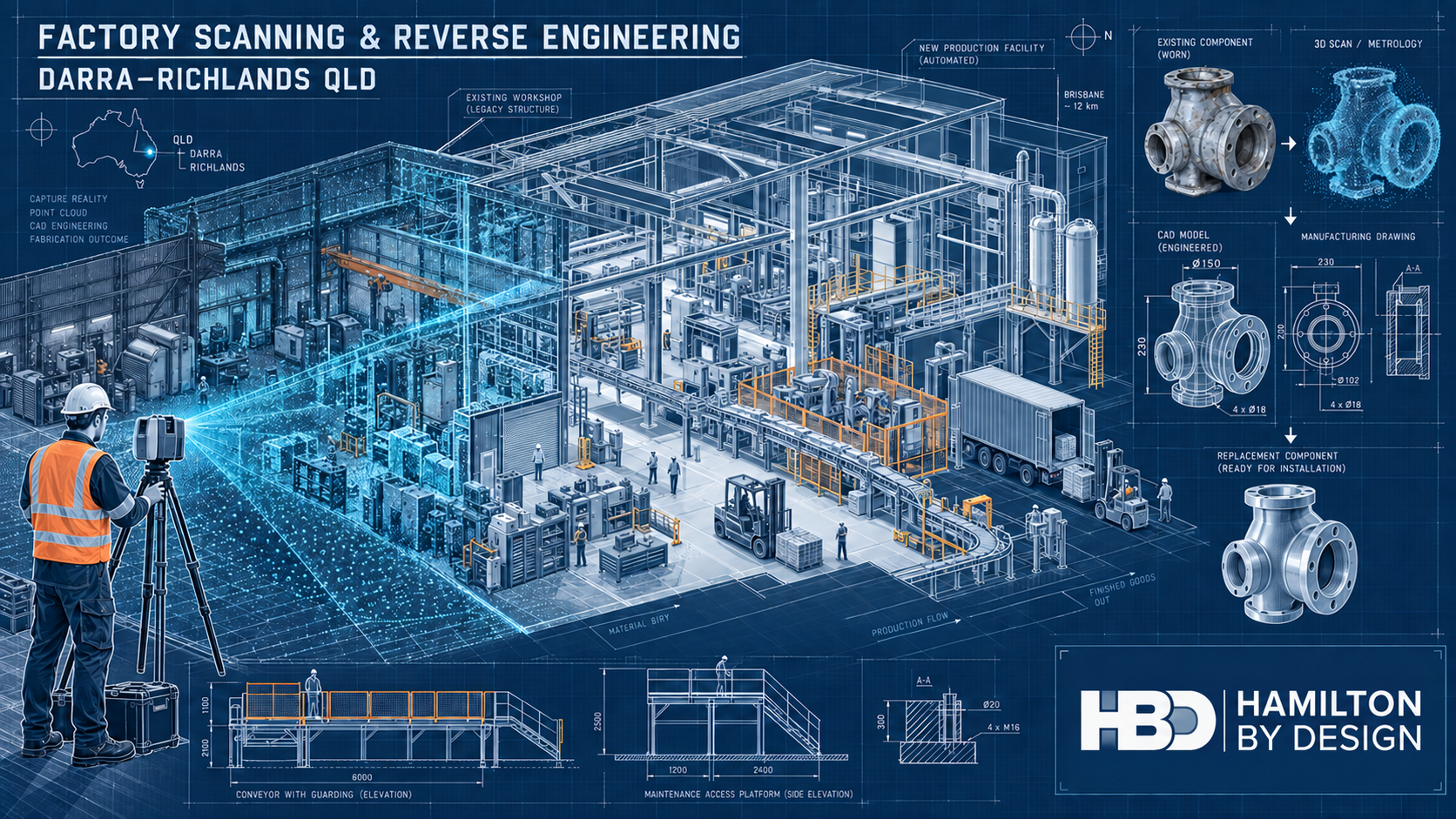
Technical drawing showing factory 3D laser scanning, point-cloud capture and machinery reverse engineering in Darra and Richlands, Queensland.

Capturing Brisbaneโ€™s industrial westโ€”from established workshops to advanced production facilities

Blue 3D LiDAR scanner icon on a tripod with scanning waves

Darra and Richlands occupy an important place in Brisbaneโ€™s industrial story. Darra developed through rail-connected brick, cement and heavy industrial activity, while neighbouring Richlands has grown into a major location for manufacturing, logistics, food and beverage production and advanced materials.

Together with Wacol, these suburbs form a connected industrial corridor rather than two isolated business districts.

That distinction matters when planning engineering work. A factory in this corridor may occupy a modern warehouse, an older purpose-built plant or a building that has been extended and repurposed several times. Machinery may have moved while services, platforms and redundant foundations remained. Original drawings may exist, but they do not always describe the factory as it stands today.

Hamilton By Design assists asset owners, manufacturers, maintenance teams and fabricators with factory scanning and reverse engineering in Darra and Richlands. Our work combines reality capture with practical mechanical understanding, turning physical plant and machinery into useful point clouds, CAD models, equipment layouts and fabrication drawings.

An industrial corridor shaped by movement and manufacturing

Darraโ€™s industrial character predates many of Brisbaneโ€™s newer business parks. Its railway connection supported early manufacturing, while the former Queensland Cement and Lime works became an important part of the districtโ€™s twentieth-century development.

The cement plant once used a long conveyor system between the Brisbane River and the Darra worksโ€”an early example of industrial infrastructure responding to geography, materials handling and production demand.

Richlands presents the contemporary side of the same story. The suburb accommodates large manufacturing and distribution facilities, including high-throughput beverage production and logistics activities supporting the nearby Wacol truck-manufacturing cluster. It is also attracting newer fields such as graphene production and advanced materials.

This produces an unusual industrial mix: legacy buildings, modern automated production lines, local workshops, major distribution facilities and nationally significant manufacturers all operate within the wider corridor.

The resulting engineering problems are rarely generic. They are connected to the condition, history and operating constraints of each site.

Why accurate factory information matters

A drawing can appear precise without being accurate.

Dimensions may have been taken from an early architectural plan, a previous tenancy layout or a machinery supplierโ€™s proposal. Columns, services and equipment may be shown in their intended positions rather than their final installed positions. Later modifications may never have been added to the drawing set.

For a preliminary concept, these differences may initially seem minor. During fabrication or installation, however, a misplaced column, an unrecorded pipe or a changed mounting point can become expensive.

These discrepancies can cause:

  • A conveyor section not to fit
  • A fabricated frame to clash with existing services
  • A replacement component to misalign with adjoining equipment
  • A machine to be too large for the proposed installation route
  • Access to a valve, bearing or motor to become restricted
  • A shutdown to be extended while steelwork is modified on site

Engineering-led 3D laser scanning provides a reliable record of visible existing conditions.

A factory survey can capture building geometry, machinery, conveyors, platforms, pipework, structural steel and surrounding obstructions in a coordinated point cloud.

Scanning does not remove the need for engineering judgement or critical manual measurements. It does, however, provide a much stronger foundation than designing from incomplete drawings and isolated tape measurements.

From point cloud to practical factory planning

The value of a factory scan is not simply the visual impact of a coloured point cloud. Its real value comes from how the information is interpreted and used.

Hamilton By Design can use registered scan data to develop:

  • Existing-condition factory plans
  • Machinery and production-line layouts
  • Building sections and elevations
  • Equipment-clearance studies
  • Conveyor and transfer arrangements
  • Installation and removal-path assessments
  • Models of selected machinery and structures
  • As-built drawings for future modifications

For a plant-layout project, the scan may be used as the spatial reference while simplified equipment envelopes are developed for arrangement planning.

This allows alternative layouts to be tested against actual columns, walls, mezzanines, accessways and existing services.

The level of modelling should suit the decision being made. A machinery-relocation study may only require reliable equipment envelopes, maintenance clearances and connection points. Detailed fabrication requires closer modelling of interfaces, supports, fasteners and critical dimensions.

Defining that distinction early avoids spending money modelling features that do not influence the engineering outcome.

Reverse engineering machinery and replacement components

Factories in Darra and Richlands often depend on equipment that has remained productive long after its original drawings or suppliers have disappeared.

A failed component may be obsolete, imported with a long lead time or previously modified to suit the site. In some cases, the physical component may be the only reliable source of dimensional information.

Reverse engineering can help recover the information needed to manufacture a replacement.

Depending on the componentโ€™s size, complexity and required accuracy, the process may combine laser scanning, metrology scanning, manual measurement, photographs and engineering inspection.

Hamilton By Designโ€™s reverse-engineering and 3D-scanning services can support items such as:

  • Rollers, pulleys and shafts
  • Brackets, frames and supports
  • Housings and covers
  • Chutes and hoppers
  • Guards and access panels
  • Machine bases and mounting plates
  • Worn or obsolete manufactured components
  • Jigs, fixtures and special-purpose tooling

Good reverse engineering is not blind copying.

A worn part records both its original function and the effects of service. Wear, distortion, corrosion and earlier repairs must be considered before deciding which surfaces should be reproduced and which should be restored.

Critical dimensions, material requirements, tolerances and mating interfaces should be agreed as part of the engineering scope.

Mechanical design for brownfield factories

Brownfield mechanical design occurs inside an environment that already has operating rules, physical constraints and production priorities.

A technically sound concept must still be accessible, maintainable, fabricable and capable of being installed safely.

Hamilton By Design provides mechanical engineering consulting for plant and machinery modifications, including:

  • Conveyors and conveyor modifications
  • Chutes, hoppers and transfer arrangements
  • Machinery-support frames
  • Pump and equipment skids
  • Guarding systems
  • Access improvements
  • Replacement assemblies
  • Production-line modifications
  • Machinery relocation
  • Brownfield plant upgrades

Scan data can be incorporated into the design environment so that proposed equipment is reviewed in relation to the real factory.

This approach is particularly useful when a project involves:

  • Adding equipment to a crowded production area
  • Relocating machinery within an existing building
  • Connecting a new conveyor to an older production line
  • Replacing equipment during a limited shutdown
  • Designing around services that cannot be moved
  • Improving maintenance access without reducing production space
  • Planning an installation before existing equipment is removed

The result should be more than a model that fits on a computer screen. It should provide a traceable path from the existing condition through design review to fabrication and installation.

Mechanical drafting and fabrication documentation

Manufacturers and fabricators require clear documentation that communicates what must be built.

Depending on the agreed scope, Hamilton By Design can prepare:

  • General arrangement drawings
  • Fabrication drawings
  • Workshop details
  • Machined-component drawings
  • Sheet-metal developments
  • Material and component schedules
  • Bills of materials
  • Cutting information
  • Installation drawings
  • As-built documentation
  • Revision-controlled drawing registers

Our fabrication and product-design services connect the site-capture and design stages with the practical information required by the workshop.

Deliverables may include native CAD files, STEP or Parasolid models, DXF profiles and controlled PDF drawing packages.

Mechanical drawings may be developed with reference to the applicable parts of the AS 1100 technical-drawing series. Fabricated steelwork may also require consideration of AS/NZS 1554, AS 4100 or AS 3990, depending on its function and classification.

The applicable standards and required level of engineering verification must be established for each project rather than assumed from the drawing type alone.

Hamilton By Design provides mechanical engineering and structural drafting within its areas of competence. Where a project requires statutory structural certification, specialist electrical design or another regulated discipline, review should be completed by an appropriately qualified practitioner.

Machinery guarding and safer access

Machinery-safety problems often emerge gradually.

A motor is replaced, a platform is added or a conveyor is extended. A guard may then be cut back to clear the modification, or it may be removed so frequently for maintenance that it is eventually left off.

Hamilton By Design provides machine-guarding design and engineering for manufacturing and fixed-plant environments.

A site assessment can consider exposed:

  • Belts and chains
  • Pulleys and rollers
  • Shafts and couplings
  • Drive assemblies
  • Conveyor nip points
  • Rotating components
  • Cutting or crushing mechanisms
  • Pneumatic and hydraulic movement

The assessment should also consider how operators, cleaners and maintenance personnel interact with the equipment.

Potential improvements can include fixed guards, removable panels, mesh enclosures, access gates, inspection openings, mounting frames and maintenance-friendly modular arrangements.

Three-dimensional scanning is particularly useful where new guards must fit around irregular machinery, pipes, cable trays, platforms or nearby structural members.

Relevant requirements may include the AS/NZS 4024 Safety of Machinery series, AS 1755 for conveyor safety and Queensland work health and safety obligations. Platforms, stairs, walkways and ladders may require consideration of AS 1657.

Guarding remains only one part of the risk-control system. Isolation, interlocks, control-system safety, operating procedures, training and inspection must also be addressed by the appropriate parties.

Supporting logistics and materials movement

Richlands is also a substantial logistics location.

Warehouses and distribution facilities face engineering issues that differ from process plants but still depend on accurate spatial information. Vehicle movement, loading docks, conveyors, pallet handling, pedestrians and maintenance activities compete for limited space.

Factory and warehouse scanning can support:

  • Loading-area layouts
  • Conveyor coordination
  • Fixed-equipment planning
  • Equipment and racking interface checks
  • Forklift and pedestrian-separation studies
  • Access-platform planning
  • Maintenance-clearance reviews
  • Tenancy modifications
  • Warehouse automation projects
  • As-built documentation

Depending on the scope, relevant standards may include AS 1657 for fixed access, AS 1755 and AS/NZS 4024 for conveyors and machinery, AS 4084 for steel storage racking and the applicable parts of AS 2890 for vehicle facilities.

Specialist traffic, racking, fire, building and structural advice should be obtained where those disciplines fall outside the agreed mechanical-engineering scope.

The five recurring problems facing industrial sites

1. Missing or outdated drawings

Older factories often accumulate changes that are never incorporated into the original drawing package. New projects then begin with uncertain dimensions and incomplete information.

Scanning provides a record of the visible installed condition from which updated layouts and as-built documents can be developed.

2. Obsolete replacement components

A component may no longer be supported by its manufacturer, or a replacement may have an unacceptable delivery period.

Reverse engineering can recover its geometry and provide CAD models or manufacturing drawings, subject to verification of its material, function and critical tolerances.

3. Congested machinery layouts

New equipment must often fit around production machinery, services, structures and accessways that cannot be readily relocated.

A coordinated point cloud allows proposed equipment to be reviewed against the existing environment before fabrication begins.

4. Guarding and access deficiencies

Machinery modifications can create new hazards or make older guards ineffective. Poorly designed guards may also interfere with routine inspection, cleaning and maintenance.

An engineering-led review can help develop controls that consider both worker safety and the practical operation of the plant.

5. Shutdown and installation risk

Unexpected conditions discovered during a shutdown can delay installation and production restart.

Scanning, interface verification, clash review and controlled fabrication drawings help move more decisions into the planning stage, when they are generally easier and less costly to resolve.

Controlled information for future upgrades

The first modification at a factory often creates information that remains valuable for the next project.

With agreed security and retention arrangements, Hamilton By Design can retain:

  • Registered factory point clouds
  • Equipment layouts
  • Machine models
  • Component scans
  • Manufacturing CAD
  • Fabrication drawings
  • Dimensional inspection records
  • Site photographs
  • Approved drawing revisions
  • Replacement-component histories

This creates a practical digital engineering record.

When another component fails or a production line is altered, the client may be able to begin with known information rather than recommissioning the entire investigation. Revision states and documented assumptions also help distinguish surveyed conditions from proposed and approved designs.

Confidentiality remains essential. Proprietary machinery, production processes and site-security information should be handled according to the clientโ€™s requirements, with the intended retention period and permitted reuse defined at project commencement.

A scan-to-fabrication workflow suited to operating industry

A typical project may progress through the following stages.

1. Define the operational question

Establish whether the project concerns machinery relocation, component replacement, increased capacity, safety, fabrication or asset documentation.

2. Review available information

Examine existing drawings, photographs, manuals, maintenance history and known operational constraints.

3. Capture existing conditions

Scan the relevant factory areas or components and manually verify critical features and interfaces.

4. Develop the engineering model

Convert the required geometry into fit-for-purpose CAD rather than modelling every visible feature.

5. Review interfaces and risk

Check clearances, access, clashes, fabrication constraints, installation requirements and design risks.

6. Prepare controlled deliverables

Issue models and drawings at the agreed review, approval or construction status.

7. Support fabrication and installation

Respond to technical queries and update the documentation where the approved or installed condition changes.

This workflow keeps responsibility connected from the factory floor to the drawing package.

Hamilton By Designโ€™s strength lies in combining scanning, mechanical design and drafting rather than treating reality capture as a standalone survey exercise.

Frequently asked questions

Can a factory be scanned while production continues?

Often, yes. The survey can be staged around access restrictions, cleaning windows, work shifts and operating equipment.

Movement can create incomplete or noisy scan data, and some critical areas may require a planned production pause. The scanning plan should be agreed with operations and safety personnel before mobilisation.

What information does a factory scan capture?

A terrestrial laser scan can capture visible surfaces such as machinery, columns, floors, walls, conveyors, platforms, steelwork and pipework.

It cannot see through equipment, insulation, walls, product build-up or enclosed assemblies. Concealed services and inaccessible interfaces require existing drawings, supplementary inspection or another investigation method.

Can Hamilton By Design reverse engineer a component without an original drawing?

Yes, provided the physical component and its important interfaces can be inspected and measured.

The engineering scope should identify the componentโ€™s function, material, loading, manufacturing process and tolerances. It should also determine whether wear or deformation must be corrected rather than reproduced.

Is a point cloud the same as a finished CAD model?

No. A point cloud is a measured representation of visible site geometry.

A CAD model is an interpreted engineering deliverable developed from selected scan information. The amount and accuracy of modelling depend on the clientโ€™s intended use and the agreed level of detail.

Can scan data help plan a machinery relocation?

Yes. Existing machinery and building geometry can be compared with proposed equipment envelopes to assess clearances, access, service connections and possible clashes.

Detailed installation planning may still require verification of lifting points, floor capacity, temporary works and the proposed transport path.

What standards apply to machinery modifications?

The answer depends on the machine, workplace and nature of the modification.

Common references may include AS/NZS 4024, AS 1755, AS 1657, AS 3990, AS 4100, AS/NZS 1554 and the AS 1100 technical-drawing series. Client specifications, Queensland work health and safety requirements and equipment-specific standards may also apply.

The relevant standards should be identified during engineering scope development.

Does Hamilton By Design fabricate the equipment?

Hamilton By Designโ€™s core role is scanning, mechanical design, modelling and drafting.

We can prepare fabrication-ready information and work with the clientโ€™s nominated fabricator, supporting technical queries and controlled drawing revisions throughout the manufacturing process.

Can Hamilton By Design retain the scan and models for later work?

Yes, where this is agreed with the client.

Retaining point clouds, CAD models and revision-controlled drawings can provide a valuable reference for future upgrades or replacement work. Confidentiality, access, permitted use and retention arrangements should be documented for each project.

Discuss a Darra or Richlands industrial project

Darra and Richlands combine industrial history with modern manufacturing, automation and logistics.

Their factories are often productive precisely because they have evolvedโ€”but that evolution can leave drawings, component information and machinery layouts behind.

Hamilton By Design helps reconnect the physical factory with reliable engineering information.

Whether the task involves scanning a production area, recovering an obsolete component, planning machinery relocation, redesigning a machine guard or producing fabrication drawings, our process begins with the equipment and conditions that actually exist.

Contact Hamilton By Design to discuss factory scanning, reverse engineering or mechanical design in Darra, Richlands and Brisbaneโ€™s western industrial corridor.


Hamilton By Design logo displayed on a blue tilted rectangle with a grey gradient background

Contact Us – Talk To Us

Name
Would you like us to arrange a phone consultation for you?
Address

Our clients:


Food and Process Plant Scanning Rocklea: 3D Laser Scanning, Mechanical Design and Scan-to-CAD

Technical drawing of a Rocklea food and process plant being captured with 3D laser scanning for mechanical design and scan-to-CAD.
Blue 3D LiDAR scanner icon on a tripod with scanning waves

Rocklea is one of Brisbaneโ€™s most established industrial locations. Its combination of food distribution, cold storage, process manufacturing, packaging, machinery services and transport operations gives the suburb an industrial identity that is distinctly different from a modern greenfield estate.

The Brisbane Markets precinct is central to this identity. Fresh produce arrives, moves through wholesale and storage facilities, and is dispatched to businesses across Queensland. Around this activity is a wider network of refrigerated transport providers, food businesses, packaging operations, warehouses, maintenance contractors and industrial service companies.

These businesses frequently operate within facilities that have changed over many years. Production lines are extended, machinery is replaced, conveyors are rerouted and services are added as operational requirements develop. Unfortunately, the original drawings do not always keep pace with these changes.

Hamilton By Design assists Rocklea businesses by combining 3D laser scanning with mechanical engineering, reverse engineering, CAD modelling and fabrication drafting. This engineering-led approach provides accurate information about existing plant and helps turn that information into practical upgrade solutions.

Why Rocklea is different

Rocklea is located approximately 10 kilometres south-west of the Brisbane CBD and has convenient access to the Ipswich Motorway, Beaudesert Road and Ipswich Road. Its proximity to the Acacia Ridge freight precinct also supports the movement of materials and finished goods through road and rail networks.

The suburbโ€™s industrial activity is strongly influenced by food, produce and logistics. This creates operating patterns that are not always obvious to people unfamiliar with Rocklea.

Many businesses begin receiving and dispatching goods well before standard office hours. Trucks, forklifts, produce buyers and warehouse personnel may already be active early in the morning. Food-processing and packaging facilities may also work across multiple shifts, followed by planned cleaning and washdown periods.

This means that plant scanning and engineering inspections must be carefully scheduled. A successful site visit may need to avoid peak receival periods, forklift congestion, sanitation activities or production processes that restrict access.

Rockleaโ€™s flood exposure is another important local consideration. Conditions vary between properties, but flooding has affected parts of the suburb and remains relevant to plant owners, maintenance teams and asset managers. Maintaining accurate digital records of machinery, equipment layouts and services can support future maintenance, recovery planning and asset replacement.

The problem with outdated plant drawings

Older factories often contain a mixture of original equipment, later additions and practical modifications completed during shutdowns. Even when building drawings are available, they may not show the current arrangement of machinery, conveyors, pipework, platforms, guards and services.

Common differences between drawings and actual site conditions can include:

  • Relocated production machinery
  • Modified conveyor elevations
  • Added guards and access gates
  • New pipework and cable routes
  • Changed floor penetrations
  • Altered cold-room arrangements
  • Added platforms or walkways
  • Temporary supports that became permanent
  • Redundant equipment that remains in position
  • Restricted maintenance access
  • Services passing through a proposed installation area

Designing from incomplete information can lead to clashes, fabrication errors and unexpected site work. A relatively small dimensional error can become expensive when a conveyor support does not align, a machine cannot pass through an access opening or a pipe route conflicts with existing equipment.

Hamilton By Designโ€™s LiDAR scanning services across Greater Brisbane help establish a reliable record of visible site conditions. Instead of relying on a limited collection of hand measurements, 3D scanning records millions of measured points that represent the surrounding plant.

What does 3D plant scanning capture?

The scanning scope should be based on the intended engineering outcome. Scanning an entire factory may be appropriate for a major rearrangement, while a localised equipment replacement may only require the machine and its surrounding interfaces.

A Rocklea food or process plant scan may capture:

  • Production and packaging machinery
  • Conveyor routes and transfer points
  • Chutes, hoppers and feed systems
  • Pumps, valves and visible pipework
  • Machinery bases and supports
  • Floors, walls and overhead clearances
  • Cold rooms and insulated panels
  • Platforms, stairs and walkways
  • Machine guards and access gates
  • Drains and visible floor penetrations
  • Loading docks and door openings
  • Ducts, cable trays and overhead services
  • Pallet-staging and maintenance areas

The point cloud can then be supplied directly or converted into selected CAD information. HBDโ€™s Scan-to-CAD services in Brisbane can produce equipment layouts, sections, elevations, general arrangements and three-dimensional models.

Not every object needs to be modelled to the same level of detail. A production-layout study may only require simplified machinery envelopes, whereas a replacement chute or guarding system may require more detailed geometry. Defining the required deliverables before modelling begins helps control cost and ensures that the resulting information is suitable for its intended use.

Scanning around live production

Food and process plants require careful site planning because access, hygiene and production continuity are closely connected.

Before scanning begins, the project team may need to consider:

  • Production schedules
  • Cleaning and washdown periods
  • Site inductions
  • Food-zone access controls
  • Personal protective equipment
  • Moving machinery
  • Forklift and truck movements
  • Restricted areas
  • Temporary pallets or stored products
  • Condensation, steam and reflective surfaces
  • Shutdown or weekend access

Temporary objects should also be identified during the site visit. Pallets, bins, hoses, mobile equipment and stored materials may appear in the point cloud, but they should not automatically be treated as permanent plant.

Where shutdown access is available, scanning can capture areas that are normally obscured or unsafe to approach. Where shutdown access is not practical, the work can often be divided into operational zones and completed progressively.

Conveyor and production-line modifications

Conveyors are essential to many Rocklea food, produce, packaging and distribution operations. They connect processes, reduce manual handling and help maintain consistent product flow. However, altering a conveyor involves more than selecting a new route.

A conveyor modification may need to consider:

  • Product size and weight
  • Required production rate
  • Belt speed and width
  • Transfer heights
  • Product accumulation
  • Drive and take-up locations
  • Cleaning access
  • Guarding
  • Operator work areas
  • Maintenance clearances
  • Forklift movements
  • Upstream and downstream machinery

Hamilton By Design can use captured site conditions to develop conveyor layouts, transfer arrangements, chutes, supports, guards and access provisions. Proposed equipment can be placed within the existing-condition model to identify clashes before fabrication begins.

HBDโ€™s manufacturing and production engineering services connect the scanning process with practical mechanical design and documentation.

This workflow is especially useful in a brownfield plant where there may be limited space between machinery, walls, overhead services and active logistics routes.

Reverse engineering for machinery and spare parts

Some Rocklea plants operate machinery that remains productive despite being many years old. Original suppliers may no longer support the equipment, and drawings for replacement parts may be unavailable.

Replacing an entire machine may not be commercially justified when only a guard, bracket, chute, cover or worn component requires attention.

Hamilton By Designโ€™s reverse-engineering and 3D-scanning services can assist with:

  • Guards and covers
  • Brackets and mounting plates
  • Conveyor components
  • Chutes and transitions
  • Equipment bases
  • Frames and housings
  • Machinery interfaces
  • Obsolete replacement parts
  • Components intended for local manufacture

Reverse engineering is not simply a process of copying a worn object. The condition of the component must be considered because corrosion, wear, distortion and previous repairs may have changed its geometry.

Material, tolerances, fit, loading and manufacturing methods should also be reviewed before a replacement component is released for production.

Machine guarding and safer access

Food and packaging machinery may expose workers to rollers, belts, chains, shafts, blades, couplings and other moving components. Conveyor drives, pulleys, transfers and take-up arrangements can also create trapping or entanglement hazards.

Hamilton By Design can capture existing guarding and machinery clearances, assist with mechanical guarding concepts and prepare drawings for fabrication.

Potential work may include:

  • Fixed machine guards
  • Belt and coupling covers
  • Conveyor nip-point guards
  • Perimeter barriers
  • Access gates
  • Removable maintenance panels
  • Guard-support frames
  • Improved stairs and platforms
  • Maintenance-access layouts

The AS/NZS 4024 series may apply to machinery safety, while AS 1657 may be relevant to fixed platforms, walkways, stairs and ladders. The applicable requirements should be confirmed for the individual machine, task and workplace.

Guarding should be considered as part of a broader plant risk-management process. The review should examine how operators use the machine, how cleaning is performed, how jams are cleared and how maintenance personnel gain access.

Designing for cleaning and maintenance

Food-production equipment must be accessible for cleaning as well as operation. A layout that improves throughput may create new problems if it leaves narrow gaps, traps product or prevents workers from reaching areas that require inspection.

The relationship between equipment and the surrounding area can influence:

  • Washdown access
  • Drainage
  • Standing water
  • Product accumulation
  • Pest harbourage
  • Corrosion
  • Access beneath conveyors
  • Removal of guards
  • Maintenance of motors and bearings
  • Separation of different work zones

A registered point cloud helps the project team understand these relationships before equipment is moved or fabricated.

Hamilton By Design can provide the scanning, mechanical design and drafting information, while the clientโ€™s production and food-safety personnel can review the proposed arrangement against site-specific hygiene procedures.

Internal logistics and material movement

Rockleaโ€™s food and process operations depend on the efficient movement of materials. Incoming goods may pass through receiving, cold storage, preparation, processing, packing, palletising and dispatch.

A production-line modification can affect this entire sequence. New machinery may improve one process while unintentionally reducing forklift access or occupying an important pallet-staging area.

HBD can capture and document:

  • Loading docks
  • Door openings
  • Cold-room access
  • Pallet-staging areas
  • Conveyor connections
  • Forklift and pedestrian interfaces
  • Machinery-removal routes
  • Maintenance areas
  • Storage and dispatch interfaces

Alternative arrangements can then be developed using reliable spatial information. This supports discussions between operations, maintenance, safety and project personnel before a preferred layout is selected.

Mechanical drafting and fabrication drawings

Once a design has been reviewed, Hamilton By Design can develop mechanical documentation for quoting, fabrication and installation.

Typical deliverables include:

  • General arrangement drawings
  • Production-line layouts
  • Conveyor drawings
  • Chute and transition drawings
  • Machine-guarding details
  • Platform and access layouts
  • Pipe-routing drawings
  • Workshop and fabrication drawings
  • Cutting profiles and DXF files
  • STEP and Parasolid models
  • Installation drawings
  • As-built updates

HBDโ€™s engineer-led SolidWorks drafting services in Queensland help maintain continuity between site capture, mechanical modelling and fabrication documentation.

This continuity is important because the person preparing the drawings can work directly with the captured site data rather than relying on information passed through several unrelated providers.

A practical scan-to-upgrade process

A Rocklea plant-upgrade project can generally follow five stages.

First, the client and HBD define the operational problem, required deliverables and limits of the work.

Second, HBD scans the relevant plant, machinery and surrounding interfaces.

Third, the point cloud is registered and checked before the required CAD information is produced.

Fourth, proposed modifications are developed and reviewed with the clientโ€™s operations, maintenance and safety personnel.

Finally, approved drawings and models are issued for fabrication or installation under an agreed revision process.

Where appropriate, an additional scan can document the completed installation and update the plantโ€™s digital records.

Frequently asked questions

Can Hamilton By Design scan an operating food factory?

Yes. Scanning can often be scheduled around production, cleaning and dispatch activities. Access requirements, hygiene controls and moving equipment should be discussed before the visit.

What is a point cloud?

A point cloud is a digital collection of millions of measured points representing visible surfaces within the scanned area. It allows the site to be viewed and measured after the scanning work is complete.

Can a point cloud be converted into CAD drawings?

Yes. Selected parts of the point cloud can be converted into equipment layouts, general arrangements, sections, elevations and three-dimensional CAD models.

Can HBD scan a single machine or conveyor?

Yes. The scope can range from one component or machine interface to a complete production area. The surrounding geometry should be sufficient to support the intended modification.

Can laser scanning detect hidden services?

No. Laser scanners record visible surfaces and cannot see through walls, floors, cladding or equipment. Concealed services may require existing records or specialist detection methods.

Can HBD assist with machinery relocation?

Yes. HBD can scan the existing machinery and its proposed destination, develop layout information and assist with mechanical interface and clearance checks.

Can HBD help with machine guarding?

Yes. HBD can document existing conditions, assist with mechanical guarding concepts and prepare fabrication drawings. The work should form part of the clientโ€™s wider machinery risk-management process.

What project data can HBD retain?

Subject to agreed confidentiality and retention requirements, HBD can retain point clouds, equipment layouts, CAD models, machinery interfaces, guarding surveys and modification drawings.

Engineering support for Rocklea plants

Rockleaโ€™s concentration of food handling, manufacturing, packaging, cold storage and distribution creates substantial opportunities for plant improvement. It also creates engineering challenges because modifications must often be completed within congested facilities and limited shutdown periods.

Accurate existing-condition data provides a stronger foundation for these decisions.

Hamilton By Design combines industrial 3D scanning with mechanical engineering, reverse engineering, CAD modelling and fabrication drafting. From a single machinery interface to a complete production-line upgrade, the objective is to reduce assumptions and provide practical information that clients, fabricators and installers can use.

For assistance with food-production-line scanning, factory scan-to-CAD, conveyor modifications, machine guarding or reverse engineering in Rocklea, contact Hamilton By Design to discuss the plant, the proposed change and the required deliverables.


Hamilton By Design logo displayed on a blue tilted rectangle with a grey gradient background

Contact Us – Talk To Us

Name
Would you like us to arrange a phone consultation for you?
Address

Our clients:
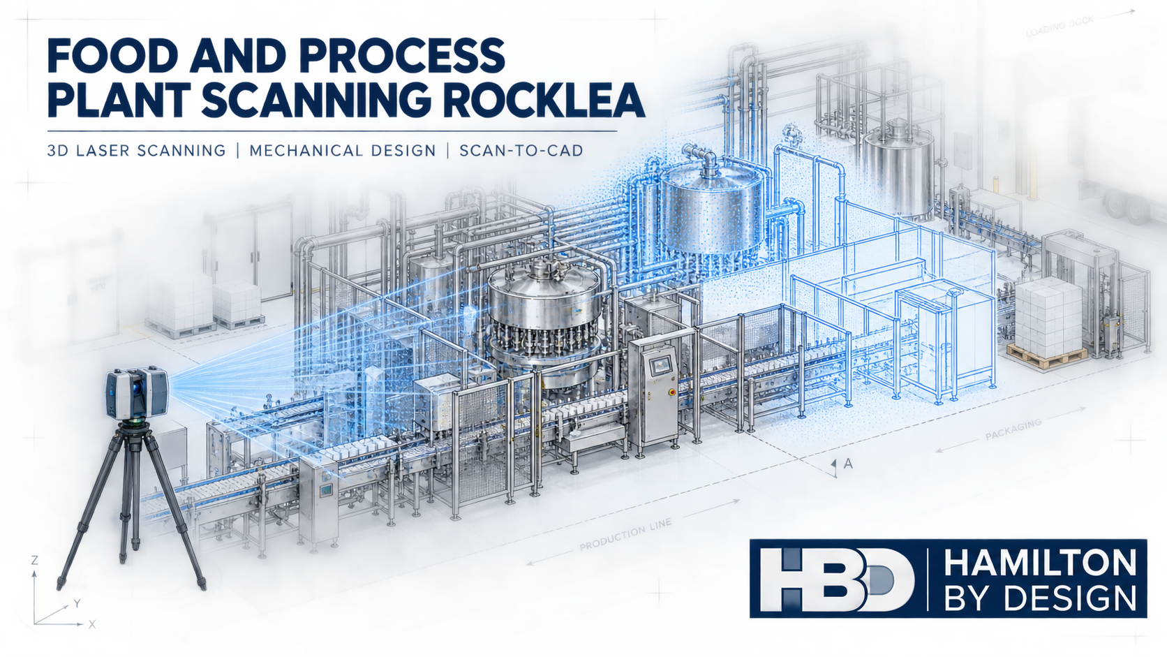


Industrial 3D Laser Scanning Acacia Ridge: Engineering for a Working Freight and Manufacturing Precinct

Hamilton By Design industrial 3D laser scanning an Acacia Ridge rail workshop, with point-cloud data transitioning into a CAD model and guarded conveyor upgrade.
Blue 3D LiDAR scanner icon on a tripod with scanning waves

Acacia Ridge is not simply another industrial suburb on Brisbaneโ€™s southern side. It is a place where manufacturing, rail freight, equipment servicing, fabrication and distribution operate within the same tightly connected precinct. Workshops sit near large warehouses, heavy vehicles share access routes with forklifts and pedestrians, and new automated equipment is often installed inside buildings that have been altered repeatedly over several decades.

For engineering teams, that mixture creates a recurring problem: the physical plant that exists today may be very different from the drawings held in the office.

Hamilton By Design provides industrial 3D laser scanning in Acacia Ridge to help manufacturers, rail-related businesses, fabricators and logistics operators establish a reliable record of their existing facilities. The resulting point cloud can then support machinery layouts, brownfield modifications, reverse engineering, safety improvements and fabrication-ready documentation.

Unlike a survey undertaken only to collect dimensions, Hamilton By Design connects site capture with mechanical engineering services, CAD modelling and practical fabrication knowledge. This means the information is collected with its eventual engineering use in mind.

An Industrial Location Shaped by Rail

The defining feature of Acacia Ridge is its relationship with rail freight. The suburb contains a major intermodal terminal at the northern end of the interstate rail corridor. It is also associated with the interface between Australiaโ€™s 1,435 mm standard-gauge network and Queenslandโ€™s 1,067 mm narrow-gauge system.

That break-of-gauge function gives Acacia Ridge a role that few other Queensland industrial locations share. Freight may move between rail systems or between trains and road vehicles, while nearby workshops and industrial businesses support the equipment, vehicles and infrastructure required to keep those movements operating.

From an engineering perspective, rail-related sites present unusual spatial demands. A proposed platform, service frame, workshop machine or maintenance structure must fit the building, but it may also need to respect vehicle envelopes, track interfaces, overhead equipment, lifting zones, access restrictions and safe working distances.

These relationships are difficult to understand from isolated tape measurements or incomplete drawings.

A registered 3D point cloud provides a spatial record of the visible site at the time of capture. Engineers and project teams can revisit that dataset after the site visit, take additional measurements and examine how surrounding assets may affect the proposed work.

Where a project is being managed from another city, the point cloud also gives designers, fabricators and asset owners a shared visual reference.

Why Accurate Existing-Condition Information Matters

Many Acacia Ridge facilities have been operating for years. During that time, machinery may have been relocated, conveyors extended, platforms added, services rerouted and safety guarding replaced. These changes are not always transferred back into the original drawings.

This creates uncertainty at precisely the time when certainty matters most: during an upgrade, installation or short shutdown.

An inaccurate column position can prevent a skid from being moved into place. An undocumented pipe or cable tray can conflict with a new conveyor. A flange shown in the wrong orientation can result in field modification, while an overlooked access requirement can make routine maintenance unnecessarily hazardous.

Hamilton By Designโ€™s 3D laser scanning engineering capability can capture the relevant workshop, plant or equipment within its surrounding context.

The scope can include:

  • Building geometry
  • Machinery and production equipment
  • Platforms, walkways and stairs
  • Accessways and maintenance zones
  • Visible pipes, ducts and services
  • Equipment supports
  • Loading areas
  • Critical mechanical interfaces

The required level of detail is agreed before scanning so that the survey remains focused on the engineering decision rather than collecting data without a defined purpose.

Factory Layouts That Account for Real Operations

Factory rearrangement is rarely a matter of fitting rectangles onto a floor plan. Machinery requires operating space, access for maintenance, safe material flow and, in some cases, room to remove large components. Forklifts need practical travel paths, operators need safe access, and production lines must connect at workable heights and orientations.

In Acacia Ridge, external logistics can be just as important as internal production. Loading docks, container movements, truck access and storage areas may all influence the preferred machinery arrangement.

Hamilton By Design can convert selected scan data into a simplified CAD layout showing the features needed for planning. Alternative arrangements can then be considered before machinery is disconnected.

This allows the project team to examine questions such as:

  • Will the equipment physically fit through the proposed access route?
  • Are maintenance and component-removal zones adequate?
  • Will a relocated machine conflict with columns, services or emergency access?
  • Can forklifts and pedestrians be separated more effectively?
  • Do conveyors and associated machines connect at the correct elevation?
  • Is there sufficient room for lifting and installation equipment?
  • Will the proposed arrangement affect loading or warehouse operations?

The aim is not merely to create a visually impressive model. It is to give decision-makers useful information before physical work begins.

Scan-to-CAD for Brownfield Modifications

Brownfield work brings new design into contact with existing geometry. The new item may be accurately modelled, but the installation can still fail if the surrounding plant has been represented incorrectly.

Through reverse engineering and scan-to-CAD studies, Hamilton By Design can develop the amount of CAD geometry appropriate to the task.

A project may require a detailed equipment model, a simplified interface model or only the critical surfaces and connection points.

Typical applications in Acacia Ridge could include:

  • Conveyor, chute and transfer-point modifications
  • Machinery and pump skids
  • Workshop platforms and maintenance access
  • Pipework, ductwork and equipment tie-ins
  • Guarding around existing drives and production machinery
  • Fabricated frames and equipment supports
  • Loading-dock or warehouse equipment changes
  • Installation studies for new automated plant
  • Workshop crane and lifting-access reviews
  • Replacement structures around existing machinery

Model detail should be matched to the projectโ€™s needs. Modelling every visible bolt is unnecessary for a general layout, while a replacement component may require significantly closer inspection, conventional measurement and tighter dimensional control.

This project-specific approach helps control modelling costs while ensuring that the information needed for design, fabrication and installation is available.

Reverse Engineering Components That Are No Longer Supported

Older machinery often remains productive long after its original drawings or replacement parts have become unavailable. When a component is worn, damaged or obsolete, reverse engineering can provide a path towards local manufacture.

For suitable components, Hamilton By Design can combine detailed scanning, photographs and physical measurements to develop:

  • A digital mesh
  • A parametric CAD model
  • STEP or Parasolid files
  • Manufacturing drawings
  • Interface drawings
  • Dimensional inspection records
  • Controlled design revisions

Critical interfacesโ€”such as shafts, bores, bolt patterns, mating faces and overall envelopesโ€”can be recorded and controlled through the design process.

However, a scan records surface geometry. It does not automatically reveal material grade, heat treatment, internal defects, original tolerances or the loading history of the part. These matters must be established through available records, testing and engineering assessment.

This distinction is especially important where the component is safety-critical, highly loaded or subject to fatigue.

A worn component should not simply be copied without considering how much material has been lost or how its original geometry may have differed from the scanned condition. The engineer must separate the existing worn shape from the likely design intent.

Guarding, Access and Safer Maintenance

Acacia Ridgeโ€™s mix of production equipment, conveyors, workshops and mobile plant means that machinery safety is an important part of many upgrade projects. New equipment can also expose shortcomings in older guarding or create new access conflicts.

Hamilton By Design can use scan data to support fixed guards, perimeter guarding, maintenance platforms and access improvements. Its machine guarding design and verification services consider the real location of hazards, foreseeable access and the need to maintain the equipment without encouraging unsafe workarounds.

Potential services include:

  • Guarding inspections and gap assessments
  • Fixed and mesh guard design
  • Perimeter guarding layouts
  • Conveyor and drive guarding
  • Access-prevention measures
  • Guard-support frames and fixings
  • Maintenance-opening reviews
  • Platform, stair and ladder improvements
  • Fabrication drawings for guarding modifications
  • As-installed guarding records

Depending on the scope, the engineering approach may refer to the AS/NZS 4024 Safety of Machinery series, ISO 12100 risk-assessment principles and AS 1657 for fixed platforms, walkways, stairs and ladders. Relevant Queensland work health and safety duties must also be addressed.

Where electrical interlocks or safety-related control systems are involved, specialist functional-safety or electrical engineering may also be required. Hamilton By Designโ€™s role and the limits of any assessment should be stated clearly in the project documentation.

Engineering for Logistics and Materials Handling

Acacia Ridge businesses operate within an environment shaped by freight movements. Trucks, containers, forklifts, railway equipment, warehouse staff and maintenance workers may all interact within a limited area.

An efficient layout must therefore consider more than production output. It must also consider how materials arrive, move through the facility and leave the site.

Hamilton By Design can assist by recording and developing layouts for:

  • Loading and unloading areas
  • Conveyor systems
  • Forklift travel paths
  • Pedestrian access
  • Storage zones
  • Equipment maintenance areas
  • Truck and container interfaces
  • Workshop entrances
  • Crane and lifting zones
  • Machinery operating envelopes

Relevant standards may include the AS/NZS 4024 series, AS 1657, AS 2359 for powered industrial trucks, AS 4084 for steel storage racking, AS 1418 for cranes and hoists, and AS 4991 for lifting devices.

The applicable standards must be selected according to the specific equipment and work activity. Traffic engineering, operational rail safety and certified racking design may require additional specialist input.

Drawings That Fabricators and Installers Can Use

The value of an accurate point cloud is realised when it improves what happens next.

Hamilton By Design can develop:

  • General-arrangement drawings
  • Fabrication drawings
  • Installation details
  • Machined-part drawings
  • Sheet-metal developments
  • DXF cutting profiles
  • Bills of materials
  • Equipment layouts
  • Guarding drawings
  • Platform and access drawings
  • As-built drawing updates

Engineering drawings may be prepared with reference to the AS 1100 technical-drawing series and the relevant project, fabrication and welding requirements.

Other standards may apply according to the work, including:

  • AS/NZS 1554 for structural steel welding
  • AS 3990 for mechanical-equipment steelwork
  • AS 4991 for lifting devices
  • AS 1657 for fixed access
  • AS 4100 for steel structures
  • AS/NZS 1170 for structural design actions
  • AS 4324.1 for bulk-materials-handling equipment
  • AS 4041 for pressure piping, where applicable

The applicable standard cannot be selected from the suburb or industry alone. It must be confirmed against the asset, intended duty, client specifications and regulatory environment.

Where structural certification falls outside the mechanical engineering scope, an appropriately qualified structural engineer should be engaged. Hamilton By Design can provide mechanical design and structural drafting support without presenting that drafting as structural certification.

A Practical Project Workflow

An effective scanning project begins with the decision the client needs to make.

Before mobilisation, Hamilton By Design establishes what is being modified, which interfaces are critical, the required accuracy and what deliverables will be used by the design and fabrication teams.

The work can then progress through five practical stages.

1. Define the Engineering Requirement

The project team identifies the area to be scanned, critical dimensions, access restrictions, operational hazards and final deliverables.

2. Capture the Existing Facility

Hamilton By Design scans the agreed area and records supporting photographs, measurements, equipment details and site observations.

3. Register and Review the Point Cloud

Individual scans are registered into a coordinated dataset. The data is checked for coverage, alignment and suitability for its intended use.

4. Develop the Model or Engineering Design

The required geometry is converted into CAD. Proposed machinery, guards, frames, platforms or other components can then be designed within the existing environment.

5. Issue Controlled Deliverables

The client receives the agreed point-cloud files, models, drawings or reports. Revisions can be managed through defined review stages such as Issue for Review, Issue for Approval and Issue for Construction.

This approach maintains continuity from the site through to the drawing office. It also reduces the risk of technical intent being lost when scanning, modelling and detailing are performed as disconnected activities.

Project Data Retained for Future Upgrades

Subject to the agreed terms and the clientโ€™s security requirements, Hamilton By Design can retain:

  • Registered point clouds
  • Workshop and factory layouts
  • Machinery models
  • Rail-equipment interfaces
  • CAD assemblies
  • Dimensional records
  • Fabrication drawings
  • Design assumptions
  • Revision history
  • Safety-review records

This retained information can provide a useful baseline for later work.

A future upgrade may still require a targeted verification visit, particularly where the site has changed, but the earlier model can shorten the planning process and help define the new survey scope.

The data can also reduce reliance on the memory of individual employees. When experienced personnel leave a business, undocumented knowledge about machinery, modifications and equipment interfaces can be lost. A controlled digital engineering record helps preserve part of that knowledge for future teams.

Frequently Asked Questions

What can be captured during an Acacia Ridge factory scan?

A survey can include the building interior, machinery, conveyors, platforms, accessways, visible services, loading areas and critical equipment interfaces. The exact boundary should be determined by the intended engineering use and site-access conditions.

Can a point cloud replace all site measurements?

No. Laser scanning is highly effective for capturing complex visible geometry, but critical fits, hidden details, small bores, threads, material specifications and manufacturing tolerances may require direct measurement, testing or reference to original documentation.

Can scanning be completed while the facility is operating?

Often it can, subject to the siteโ€™s safety requirements and the nature of the operation. Moving vehicles, machinery, people, steam, dust or obstructed areas can affect capture. Some interfaces may be better recorded during a planned pause or shutdown.

Does Hamilton By Design scan rail corridors?

Hamilton By Design can assist with industrial and workshop geometry associated with rail operations where access, inductions and the agreed scope permit. Work within an operational rail corridor requires the infrastructure managerโ€™s authorisation, appropriate rail-safety arrangements and, where necessary, rail-specific specialists.

What files can be supplied?

Depending on the scope, outputs may include registered point clouds such as E57 or RCP files, 2D AutoCAD layouts, SolidWorks models, STEP or Parasolid files, fabrication drawings and PDF drawing packs.

Can Hamilton By Design reverse engineer a worn component?

Yes, where the component and available evidence make reverse engineering practical. Wear, materials, tolerances and service loads must be assessed rather than treating the scanned surface as the original design geometry.

Which standards apply to an industrial upgrade?

That depends on the equipment and scope. Common references may include AS/NZS 4024, AS 1657, AS 3990, AS 4991, AS 4100, AS/NZS 1554 and the AS 1100 drawing series. The project-specific standards and current editions should be confirmed before design begins.

Engineering Information Built Around the Real Site

Acacia Ridgeโ€™s importance comes from activity: freight moves, workshops maintain equipment, manufacturers adapt their lines and logistics facilities work to demanding schedules. That same activity makes upgrades difficult when existing information is incomplete.

Hamilton By Design helps close the gap between the physical facility and the engineering record.

By combining industrial 3D laser scanning, scan-to-CAD, mechanical design, reverse engineering and fabrication documentation, HBD gives project teams a clearer basis for planning work in complex operating environments.

If you are planning a factory rearrangement, rail-workshop modification, guarding upgrade, replacement component or brownfield installation in Acacia Ridge, contact Hamilton By Design to discuss the site, the required engineering outcome and the most useful form of deliverable.


Hamilton By Design logo displayed on a blue tilted rectangle with a grey gradient background

Contact Us – Talk To Us

Name
Would you like us to arrange a phone consultation for you?
Address

Our clients: