


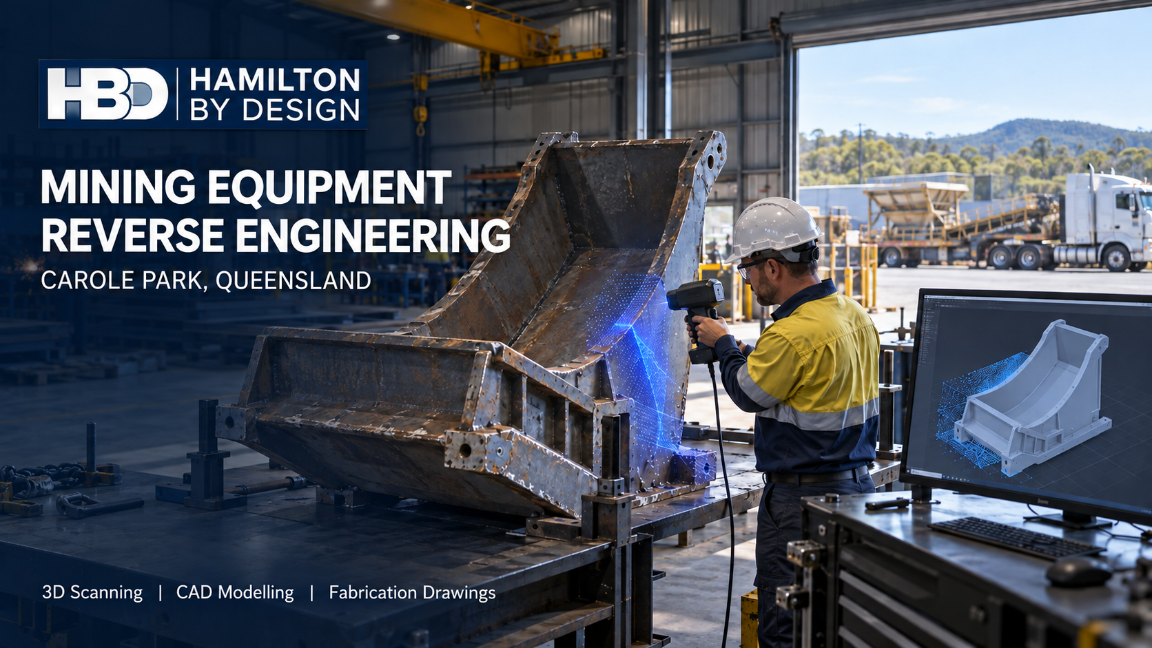

Carole Park is a practical place to solve difficult equipment problems. Within this industrial suburb in the City of Ipswich, businesses machine components, fabricate steelwork, manufacture wear-protection products and move goods across South East Queensland. Its position beside Brisbane’s western industrial corridor also gives workshops access to suppliers and transport routes. For a mining-equipment owner, that combination can make Carole Park a useful place to repair, modify or manufacture a component.
However, manufacturing capability is only part of the job. Before a workshop cuts plate or machines a replacement part, someone must establish what the existing equipment actually looks like, which dimensions matter and how the new component will fit. That becomes difficult when the original drawings are missing, the equipment has been modified or years of wear have changed its shape.
Hamilton By Design helps close that information gap through 3D scanning, reverse engineering, mechanical design and drafting. The objective is to turn an existing component or plant area into engineering data that can be checked, discussed and used for the next decision. Our broader approach to reverse engineering mining and industrial equipment starts with the asset’s function and condition, rather than assuming that a digital copy of its present shape is the right replacement.
Why Carole Park calls for a workshop-focused approach
Carole Park has a distinct industrial character. TNN Engineering describes CNC machining and fabrication work for sectors including mining and civil construction. OZQ Engineering lists fabrication, machining and resources-sector work. Wearmin operates in hose and wear protection for demanding industrial applications. These examples show the range of work carried out locally; they do not imply that the companies are Hamilton By Design clients.
That local mix suggests a particular need: engineering information that survives the handover between an equipment owner, a designer and a manufacturer. A worn chute liner may be easy to remove but difficult to define. A machined component may look straightforward until its bolt pattern, shaft fit or installed clearance is measured. A workshop may be able to fabricate an assembly quickly, yet still need reliable information about the plant it must fit.
Reverse engineering is most useful when it addresses those questions before manufacture begins. It can also reveal where the original equipment could be improved, provided the operating conditions, materials, loads and failure history are understood. Reproducing a failed detail without examining why it failed may simply repeat the problem.
Begin with the decision the scan must support
“Scan the equipment” is a starting request, not a complete scope. The right measurement method depends on what the client needs to decide.
If the aim is to relocate a conveyor or fit a new chute, a site scan can capture surrounding steelwork, walkways, pipework and other physical interfaces. If the aim is to manufacture a replacement component, closer measurement of mating surfaces, holes and critical features may be necessary. If the concern is wear, the task may involve comparing the present geometry with a nominal model or agreed reference dimensions.
Hamilton By Design uses 3D scanning and reverse engineering to develop models that serve a defined engineering purpose. The scope should identify the required deliverables, the dimensions that need direct verification and any surfaces that cannot be measured reliably while the equipment is installed.
A scan records visible geometry at a particular time. It does not, by itself, establish the original unworn profile, the material grade or every manufacturing tolerance. Where those details matter, HBD can identify the additional measurements, records or engineering assessment needed.
Replacement-component CAD for mining equipment
Mining and heavy-industrial equipment often remains in service long after its original documentation has become difficult to find. Components may have been repaired, adjusted or made locally over several decades. A replacement therefore needs to be understood in relation to the equipment around it.
For a component brought into a Carole Park workshop, the process might begin with a mesh or measured profile. The model is then developed around functional features: mounting faces, shaft centres, bolt-hole positions, contact surfaces and the space needed for installation. Where wear has distorted a surface, the model should distinguish measured condition from proposed replacement geometry.
Depending on the job, the outputs may include an editable CAD model, a dimensional report, a general arrangement, a fabrication drawing or a file suitable for manufacturing review. The required accuracy should be set by the component’s function. A broad clearance envelope and a precision-machined fit call for different verification methods.
Keeping the approved model and drawing revision also has value beyond the first replacement. The next maintenance team can begin with an identified design record rather than repeating the entire measurement exercise.
Chutes, conveyors and wear parts
A transfer chute is more than a collection of folded plates. Its performance depends on material flow, wear, access for maintenance and the position of the conveyor equipment around it. A replacement made from an old drawing can create problems if the supporting structure or adjoining plant has changed since that drawing was issued.
For these projects, HBD can capture the installed equipment, model the available space and develop chute or conveyor modifications in CAD. The model allows the team to inspect interfaces and discuss how a proposed assembly will be fabricated, transported and installed. HBD’s mechanical engineering work for mining infrastructure includes materials-handling equipment, transfer stations and plant upgrades.
Wear-part modelling can follow a similar path. A liner or replaceable plate needs geometry that fits the parent equipment, appropriate attachment details and a practical removal path. Recording its geometry and manufacturing revision helps an owner compare later replacements and document changes made in response to wear.
Engineering review should be matched to the proposed change. A new liner profile, altered chute support or conveyor modification may raise different questions about loads, maintenance access and machine safety.
From Carole Park workshop to operating plant
Some assemblies are built in Carole Park but installed at a mine or processing facility elsewhere. In that situation, the workshop and site must share a reliable description of the existing conditions. Even a well-made assembly can be difficult to install if a support is out of position or the available lifting space was assumed rather than measured.
HBD’s scan-to-CAD workflow for Brisbane and Queensland projects brings existing-condition data into a model that can be used to review proposed work. A coordinated model may expose a clash before fabrication, show where another site measurement is needed or help the team plan an installation sequence.
The useful deliverable is not always a complete model of the entire facility. For a specific replacement, it may be enough to capture the assembly’s mounting points, adjacent obstructions and removal path. Defining that boundary early keeps the survey focused on the decision it needs to support.
Safety and access are part of the design
Mining equipment modifications can affect people who operate, clean and maintain the plant. A new guard may restrict access to a wear part. A relocated chute may change how a blockage is cleared. A revised conveyor arrangement may create a new point where moving components can be reached.
Queensland WorkSafe has documented serious conveyor incidents and emphasises guarding, isolation and risk controls for plant work. HBD can assist by measuring existing arrangements, modelling proposed guards and access changes, and preparing drawings for review within the client’s risk-management process. The assessment must consider the actual tasks people perform, including maintenance and abnormal conditions, rather than only normal operation.
Relevant references may include the AS/NZS 4024 machinery-safety series and AS/NZS 4024.3610:2015 for conveyor-system safety. AS 1657:2018 may apply when a project includes fixed walkways, platforms, stairs or ladders. The applicable requirements depend on the equipment and the proposed scope; listing a standard on a drawing is not a substitute for assessing the design against it.
A useful record for future repairs
A good reverse-engineering project should leave the owner better informed about the asset. Subject to the client’s agreed data arrangements, HBD can retain equipment point clouds, component meshes, CAD models, wear-part geometry, dimensional reports, fabrication drawings and manufacturing revisions.
Those records can help distinguish an approved design from an earlier workshop modification. They also give a future maintenance team a starting point when a part wears again or a similar asset needs attention. The value lies in knowing what was measured, what was inferred, what was changed and which revision was manufactured.
Frequently asked questions
Can you reverse engineer a worn mining-equipment component?
Yes, although the worn surface should not automatically become the replacement shape. HBD can scan or measure the component, identify critical interfaces and develop proposed CAD geometry. The owner’s operating records, comparable parts and engineering review may be needed to establish the intended profile.
Is 3D laser scanning accurate enough to manufacture a replacement part?
That depends on the size of the part and the tolerances that matter. A site scan can be highly useful for overall geometry, clearances and installation interfaces. Precision fits, small holes or machined surfaces may require closer-range measurement or direct dimensional verification. The measurement plan should be agreed before scanning.
Can a component be scanned in a Carole Park workshop and fitted at a remote mine?
Potentially. The workshop component and its installed interfaces must both be understood. For a critical fit, HBD can define which site dimensions, mounting features and surrounding clearances need to be captured before the replacement is finalised.
Do you provide fabrication drawings as well as a 3D model?
Yes, when fabrication documentation is included in the agreed scope. A 3D model, a general arrangement and a fabrication drawing serve different purposes. The drawing package should identify the details the manufacturer needs, along with the applicable revision and any dimensions requiring confirmation.
Can you help improve a chute rather than reproduce it exactly?
Yes. HBD can document the existing chute and develop a revised mechanical arrangement for review. An improvement should be based on the material handled, observed wear or blockage, available space, support conditions and maintenance needs. Additional analysis or specialist input may be required for particular changes.
Which Australian standards apply?
The answer depends on the equipment and work being undertaken. Machinery guarding and risk reduction may call for parts of AS/NZS 4024; conveyor modifications may involve AS/NZS 4024.3610; fixed access may involve AS 1657. Steelwork associated with mechanical equipment may call for AS 3990, where its scope applies. The relevant standards are selected for the actual design, not applied as a generic list.
Discuss a component or plant upgrade
If an equipment part has no reliable drawing, a chute needs modification or a new assembly must fit existing plant, Hamilton By Design can help define the measurement and engineering work required. Send through photographs, available drawings, the equipment location and a brief description of the problem. We can then discuss what needs to be captured, what must be verified and which deliverables will help you move toward manufacture or installation.

Contact Us – Talk To Us
Our clients:
























