Structural Drafting Sydney

Structural drafting workflow showing LiDAR scanning, point cloud modelling, and steel detailing for accurate construction in Sydney

Structural Drafting Sydney | Engineering-Grade CAD & Steel Detailing

Engineering-Grade Detailing for Real-World Construction
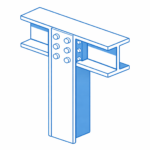
Structural steel I-beam bolted connection with column in isometric view.

Structural drafting in Sydney is often treated as a documentation exercise โ€” but in reality, it sits at the critical junction between design intent and construction reality.

At Hamilton By Design, we approach structural drafting as an engineering-led process, not just linework. By combining 3D LiDAR scanning, SolidWorks modelling, and practical site experience, we ensure drawings reflect what is actually built โ€” not what was assumed.


Why Structural Drafting Matters in Sydney

Sydney presents unique challenges:

  • Dense urban environments
  • Brownfield upgrades and legacy infrastructure
  • Tight construction tolerances
  • Multi-disciplinary coordination (mechanical, civil, structural)

Traditional drafting methods often rely on:

  • Outdated drawings
  • Manual measurements
  • Assumptions based on design models

This creates risk.


3D LiDAR scanning and 3D modelling service button โ€” laser scanner capturing a point cloud for engineering and CAD modelling
Mechanical engineering services

The Problem with Traditional Drafting

In many projects, structural drawings are created without verifying real-world conditions. This leads to:

  • Misaligned steelwork
  • Rework on-site
  • Fabrication errors
  • Cost overruns
  • Delays during installation

The issue is simple:
Design models โ‰  As-built reality


Our Approach: Scan โ†’ Model โ†’ Detail

We solve this using an engineering-grade workflow:

1. 3D Laser Scanning (LiDAR)

Using FARO terrestrial scanners, we capture accurate site geometry:

  • Steel structures
  • Concrete interfaces
  • Existing services
  • Connection points

Deliverables:

  • Registered point clouds (.E57, .RCP)
  • Full site coverage with traceable accuracy

2. Point Cloud to CAD Modelling

We convert reality into usable engineering models:

  • Clean, simplified geometry
  • Fabrication-ready references
  • Clash-aware modelling

3. Structural Drafting & Detailing

We produce:

  • GA drawings
  • Shop drawings
  • Sections and elevations
  • Connection details
  • Platework and steel member detailing

All drawings are structured for:

  • Fabrication
  • Installation
  • Compliance

Why Engineering-Led Drafting Wins

Most drafting services are CAD-driven.
We are engineering-driven.

This means:

  • Load paths are understood
  • Connections are practical
  • Fabrication methods are considered
  • Site constraints are built into the design

Sydney Project Applications

Our structural drafting services are ideal for:

  • Industrial plants
  • Mining infrastructure
  • Structural upgrades
  • Conveyor systems and transfer stations
  • Platforms, walkways, and access systems
  • Retrofit steelwork in existing buildings

The Role of Digital Engineering & Governance

By integrating with the 3DEXPERIENCE platform, we provide:

  • Version-controlled drawings
  • Full revision history
  • Chain of custody for engineering data
  • 24/7 access for stakeholders

This ensures:

  • One source of truth
  • Reduced miscommunication
  • Audit-ready documentation

Key Benefits

  • Reduced rework and site delays
  • Accurate fabrication first time
  • Faster project delivery
  • Improved safety and compliance
  • Better coordination across disciplines

Hamilton By Design logo displayed on a blue tilted rectangle with a grey gradient background

Hamilton By Design

Structural drafting in Sydney should not rely on guesswork.

By combining:

  • Reality capture (LiDAR scanning)
  • Engineering modelling
  • Practical drafting experience

Hamilton By Design delivers drawings that match reality โ€” not assumptions.


Industries We Support

Our structural drafting services support manufacturing facilities, industrial plants, commercial buildings, rail infrastructure, water treatment facilities and resource sector projects throughout Sydney.

Hamilton By Design prepares structural steel drawings, fabrication details, general arrangement drawings and as-built documentation to support construction, maintenance and asset improvement projects.

Hamilton By Design provides structural drafting services throughout Sydney CBD, Parramatta, Liverpool, Penrith, Chatswood, Alexandria, Mascot, Newcastle and the Central Coast. We prepare structural steel drawings, fabrication details, general arrangement drawings and as-built documentation for industrial, infrastructure and commercial projects.


Call to Action

If your project requires accurate, buildable structural drawings, contact:

Hamilton By Design
Engineering-led drafting and 3D scanning services across Sydney

Our clients

3D CAD Modelling Australia service banner for Hamilton By Design

Talk to Us – Contact Us

Name
Would you like us to arrange a phone consultation for you?
Address
3D Scanning Sydney banner promoting engineering-grade 3D laser scanning, LiDAR scanning, and reality capture services by Hamilton By Design.
Mechanical Engineering Sydney banner with white text on a blue background representing Hamilton By Design's mechanical engineering services in Sydney.
Mechanical Drafting and 3D Modelling Sydney banner highlighting Hamilton By Design's CAD drafting, 3D modelling, and engineering design services in Sydney.


Mechanical Engineering | Structural Engineering


Hamilton By Design provides engineering-led 3D scanning, LiDAR scanning, mechanical engineering and digital engineering services throughout Sydney and Greater Sydney.

Explore our related Sydney services:


  • 3D Scanning Sydney โ€“ Engineering-grade terrestrial laser scanning, as-built surveys and point cloud capture for industrial, infrastructure and commercial projects.
  • Reality Capture Sydney โ€“ High-accuracy reality capture, digital twins, asset documentation and engineering-grade site verification.
  • Scan to CAD Sydney โ€“ Convert point cloud data into AutoCAD, SolidWorks, Inventor and other engineering-ready CAD deliverables.
  • Point Cloud Modelling Sydney โ€“ Engineering-grade point cloud processing, clash detection, as-built verification and 3D modelling.
  • Mechanical Engineering Sydney โ€“ Mechanical design, plant upgrades, materials handling systems, conveyors, chutes, platforms and engineering support.
  • Structural Drafting Sydney โ€“ Structural steel drafting, fabrication drawings, GA drawings, workshop detailing and as-built documentation.

Hamilton By Design supports projects throughout Sydney CBD, Parramatta, Liverpool, Penrith, Blacktown, Chatswood, Alexandria, Mascot, Newcastle and the Central Coast.


Blue banner graphic displaying the text "Point Cloud to CAD - Australia" in large white lettering, representing point cloud processing, scan-to-CAD conversion and digital engineering services across Australia.
Blue banner graphic displaying the text "Scan to CAD Sydney" in large white lettering, representing engineering-led point cloud to CAD conversion, LiDAR scanning and digital engineering services in Sydney.
Blue banner graphic displaying the text "Reality Capture Sydney - CBD" in large white lettering, representing engineering-led reality capture, LiDAR scanning and digital engineering services within Sydney CBD commercial buildings and infrastructure.

High Court Changes Engineering Liability

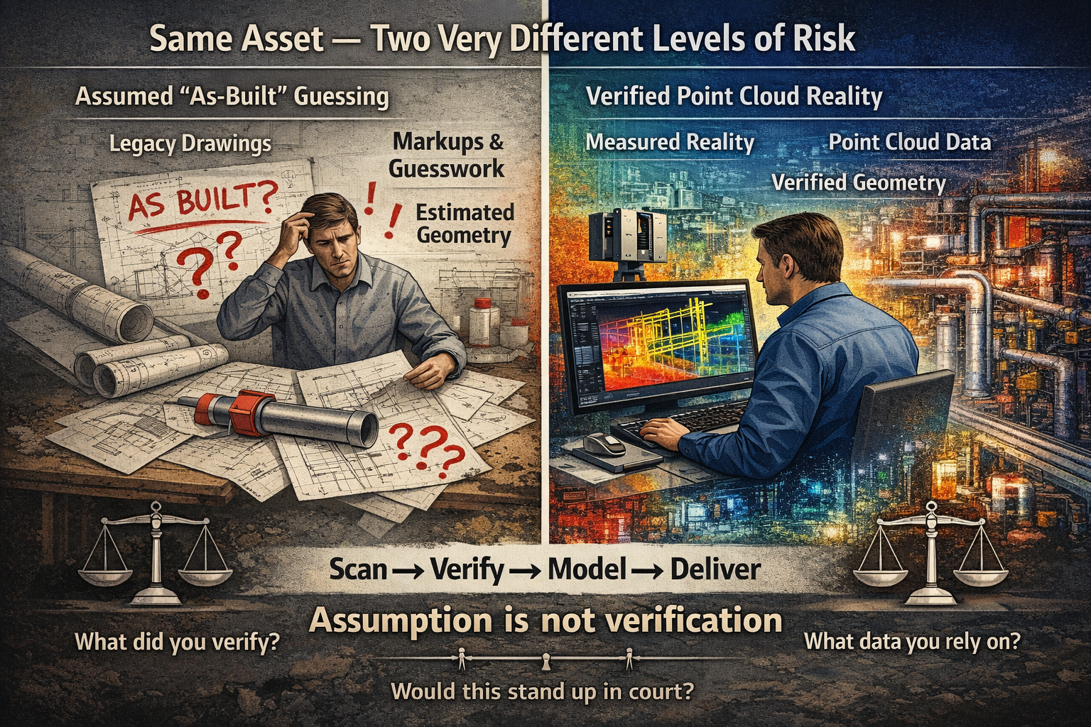
Split-screen engineering graphic comparing assumed as-built drawings with verified point cloud scanning data, highlighting the difference between estimated geometry and measured reality.

The High Court Just Changed Engineering Liability โ€” Why โ€œAs-Built Guessingโ€ Is No Longer Enough

The recent High Court decision in Pafburn Pty Ltd v The Owners โ€“ Strata Plan No 84674 has been widely discussed across the construction and legal sectors. Most commentary has focused on developers and builders, particularly the finding that they can be held fully liable for defects and cannot rely on proportionate liability to distribute responsibility.

But for engineers, designers, and anyone working in brownfield environments, the real impact runs deeper.

This case signals a clear shift in expectation โ€” away from assumption, and toward verified reality.


3D LiDAR scanning and 3D modelling service button โ€” laser scanner capturing a point cloud for engineering and CAD modelling
Mechanical engineering services

The Hidden Risk in โ€œAs-Builtโ€ Drawings

Across many projects, particularly in retrofit, maintenance, and upgrade work, design offices rely on what are commonly referred to as โ€œas-builtโ€ drawings.

In theory, these drawings represent what has actually been constructed on site.

In practice, however, that is not always the case.

Many โ€œas-builtsโ€ are produced through:

  • Manual markups during construction
  • Redline drawings updated after installation
  • Verbal confirmation from site teams
  • Interpretation of incomplete or outdated information

In some cases, they are never formally verified at all.

This creates a fundamental problem.

The design office is making decisions based on information that may be:

  • Incomplete
  • Inaccurate
  • Or in the worst case โ€” assumed

The Question That Is Now Being Asked

Following this High Court decision, the legal environment is changing.

It is no longer sufficient to say:

โ€œI worked from the drawings provided.โ€

Instead, the question is becoming:

What should a competent engineer have verified?

This is a significant shift.

It places responsibility not just on what information was used โ€” but on whether that information should have been trusted in the first place.


Assumption vs Measured Reality

At its core, this issue comes down to a simple comparison:

Does guessing what has been built offer the same level of coverage as measured data?

The answer is increasingly clear โ€” it does not.

When geometry is assumed:

  • Tolerances are unknown
  • Deviations from design are hidden
  • Errors compound as projects progress
  • Rework risk increases

More importantly, from a legal standpoint:

There is no defensible evidence of what actually existed at the time decisions were made.


The Role of Point Cloud Scanning

This is where point cloud scanning and reality capture fundamentally change the workflow.

Rather than relying on interpretation, point cloud data provides a direct measurement of site conditions.

A properly captured scan:

  • Records millions of measured points across the asset
  • Captures geometry exactly as installed
  • Provides a timestamped dataset of site conditions
  • Can be referenced, rechecked, and validated at any time

Most importantly, it creates a feedback loop between site and design.

Instead of guessing what has been built, the design office receives:

  • Accurate geometry
  • Verified spatial relationships
  • Real-world constraints

This allows models and drawings to be developed based on reality, not assumption.


Feeding Reality Back Into the Design Office

One of the most overlooked issues in engineering workflows is the disconnect between site and design.

Information typically flows in one direction:

  • Design โ†’ Construction

But the return flow:

  • Construction โ†’ Design

Is often inconsistent or incomplete.

Point cloud scanning closes this gap.

By scanning installed conditions and feeding that data back into the design environment, engineers can:

  • Align models with actual site geometry
  • Identify clashes before fabrication or installation
  • Validate clearances and fitment
  • Reduce the risk of downstream errors

This is not just about accuracy โ€” it is about confidence.


Why This Matters More After the High Court Decision

The implications of Pafburn Pty Ltd v The Owners โ€“ Strata Plan No 84674 go beyond contractual structures.

They influence how engineering decisions are evaluated.

When something goes wrong, the question is no longer simply:

โ€œWho was responsible for the design?โ€

It becomes:

  • What information was relied upon?
  • Was it reasonable to rely on that information?
  • Could the actual conditions have been verified?

If the tools to verify existed โ€” and were not used โ€” that becomes part of the discussion.


From Design Intent to Verified Condition

The industry is moving through a transition.

Historically, projects were driven by:

  • Design intent
  • Nominal dimensions
  • Idealised geometry

Today, the expectation is shifting toward:

  • Verified condition
  • Measured data
  • Real-world constraints

This shift is particularly important in:

  • Brownfield upgrades
  • Industrial plants
  • Mining infrastructure
  • Retrofit and modification projects

Where existing conditions rarely match original design documentation.


Practical Implications for Engineers

For engineers and designers, this means a change in approach.

Relying solely on drawings โ€” particularly for existing assets โ€” introduces risk.

A more robust workflow includes:

  • Verification of critical geometry
  • Clear documentation of data sources
  • Separation of assumed vs measured information
  • Use of reality capture where accuracy matters

This is not about replacing engineering judgement.

It is about supporting that judgement with evidence.


Conclusion: Coverage, Confidence, and Accountability

At the centre of this discussion is a simple idea:

Not all information offers the same level of coverage.

โ€œAs-builtโ€ drawings based on interpretation provide one level of confidence.

Measured point cloud data provides another.

As legal expectations evolve, the difference between the two becomes more significant.

Guessing what has been built โ€” even when done carefully โ€” does not offer the same level of coverage as data that can be measured, verified, and defended.


How We Approach It

At Hamilton By Design, our workflow is built around this principle:

Scan โ†’ Verify โ†’ Model โ†’ Deliver

By capturing real-world conditions and feeding that data back into the design process, we reduce uncertainty and provide a clear basis for engineering decisions.

Not just for better outcomes โ€” but for greater accountability.


If your next project relies on โ€œas-builtโ€ drawings alone, it is worth asking:

Are they measuredโ€ฆ or assumed?

3D CAD Modelling Australia service banner for Hamilton By Design

Our clients

Structural Steel Engineering for Mining Plants

Engineers using 3D laser scanning and digital modeling to upgrade structural steel in a mining plant.

Structural Steel Design in Mining Infrastructure

Mining plants rely heavily on structural steel infrastructure to support processing equipment, conveyors, walkways, platforms, and maintenance access systems. From crushing circuits to materials handling systems, structural steel plays a critical role in maintaining safe and efficient plant operations.

Because mining environments are complex and often evolve through multiple upgrades over time, structural steel mining design requires careful engineering analysis to ensure that new infrastructure integrates properly with existing plant systems.

At Hamilton By Design, structural steel engineering is commonly used to support plant upgrades, equipment installations, and infrastructure modifications across mining and industrial facilities.


The Role of Structural Steel in Mining Plants

Mining processing plants contain large volumes of structural steel used to support equipment and provide safe access for operations and maintenance teams.

Typical structural steel infrastructure in mining plants includes:

โ€ข conveyor support structures
โ€ข transfer tower frameworks
โ€ข equipment support platforms
โ€ข access walkways and handrails
โ€ข maintenance platforms
โ€ข pipe and services supports

These structures must be designed to support heavy equipment loads while also allowing safe access for plant personnel.

Structural steel systems must also account for vibration, dynamic loads from conveyors, and environmental conditions such as dust, moisture, and corrosion.


Engineering Challenges in Structural Steel Mining Design

Mining plants present unique challenges for structural engineers. Unlike greenfield projects, many mining facilities have evolved through decades of maintenance and upgrades.

Common engineering challenges include:

โ€ข integrating new structures with existing infrastructure
โ€ข limited space around operating equipment
โ€ข unknown loads from legacy plant equipment
โ€ข structural modifications during shutdown periods
โ€ข coordinating mechanical and structural design

Because of these challenges, structural engineers must often analyse existing plant conditions before designing modifications or upgrades.


Capturing Existing Infrastructure Before Design

Before structural steel upgrades or modifications are designed, engineers often capture the existing plant infrastructure to ensure accurate integration.

Many engineering teams now use 3D laser scanning to capture detailed measurements of plant structures.

Laser scanning records millions of measurement points and creates point cloud datasets representing the geometry of conveyors, structures, platforms, and equipment.

These datasets allow engineers to understand the real plant layout before designing new structures.

Learn more about capturing existing conditions here:


Structural Steel Modelling and Engineering Design

Once accurate plant data has been captured, engineers develop structural models used to design new steelwork.

Structural steel mining design often includes:

โ€ข support frames for new equipment
โ€ข conveyor support modifications
โ€ข access platform design
โ€ข structural reinforcements
โ€ข installation support structures

These models allow engineers to evaluate loads, verify clearances, and coordinate structural work with mechanical equipment and plant infrastructure.

Engineering modelling workflows can also support fabrication by providing accurate drawings and installation details.

More information about converting scan data into engineering models can be found here:

CHPP Engineering title graphic featuring bold white text reading "CHPP Engineering" centred on a blue rounded rectangle background.
Pipework Drafting title graphic featuring bold white text reading "Pipework Drafting" centred on a blue rounded rectangle background.
3D LiDAR Scanning for Engineering Projects title graphic featuring bold white text on a blue rounded rectangle background.

Structural Engineering for Plant Upgrades

Structural steel engineering is often required when mining plants undergo upgrades or modifications.

Typical projects may include:

โ€ข installation of new conveyors
โ€ข replacement of processing equipment
โ€ข upgrades to materials handling systems
โ€ข reinforcement of aging infrastructure
โ€ข modifications to transfer towers and chutes

Because much of this work occurs during scheduled shutdowns, structural engineering preparation must often be completed before the shutdown window begins.


Structural Steel and Infrastructure Design Integration

Structural steel engineering rarely occurs in isolation. It must be coordinated with other engineering disciplines including mechanical systems, materials handling equipment, and plant infrastructure.

Successful mining infrastructure design requires collaboration between engineers responsible for:

โ€ข mechanical systems
โ€ข materials handling equipment
โ€ข plant layout
โ€ข maintenance access systems
โ€ข structural support frameworks

Digital plant models and accurate engineering documentation allow these disciplines to work together more effectively.


Hamilton By Design logo displayed on a blue tilted rectangle with a grey gradient background

Conclusion

Structural steel plays a vital role in supporting equipment and infrastructure within mining plants. Through careful structural steel mining design, engineers ensure that plant structures can support operational loads while providing safe access for maintenance and operations teams.

By combining accurate plant data, digital engineering models, and coordinated infrastructure design, engineering teams can develop structural steel solutions that integrate effectively within existing mining plants.

Hamilton By Design provides engineering services to support mining infrastructure design, plant upgrades, and structural steel engineering projects across industrial facilities.

3D LiDAR scanning and 3D modelling service button โ€” laser scanner capturing a point cloud for engineering and CAD modelling
Mechanical engineering services
Name
Would you like us to arrange a phone consultation for you?
Address

Our clients

3D CAD Modelling Australia service banner for Hamilton By Design
3D LiDAR Scanning Darwin for engineering surveys, laser scanning, reality capture and point cloud modelling services
3D LiDAR Scanning Australia engineering services for laser scanning, reality capture, scan-to-CAD, Scan-to-BIM and as-built documentation across Australia
3D LiDAR scanning services on the Central Coast providing engineering-grade laser scanning, point cloud capture, scan-to-CAD modelling and industrial reality capture for infrastructure and industrial projects.
3D LiDAR Scanning Perth for engineering surveys, laser scanning, reality capture and point cloud modelling services
3D LiDAR Scanning Sydney for engineering surveys, laser scanning, reality capture and point cloud modelling services
3D LiDAR Scanning Brisbane for engineering surveys, laser scanning, reality capture and point cloud modelling services
3D LiDAR Scanning Canberra for engineering surveys, laser scanning, reality capture and point cloud modelling services
3D LiDAR Scanning Newcastle for engineering surveys, laser scanning, reality capture and point cloud modelling services
3D LiDAR Scanning Adelaide for engineering surveys, laser scanning, reality capture and point cloud modelling services

Design Verification Under AS 4991

Engineer verifying lifting beam design under AS 4991 with FEA stress analysis overlay in fabrication workshop.

Design Verification Under AS 4991: What Fabricators Often Miss

In Australiaโ€™s heavy industry and mining sectors, lifting devices are routinely fabricated under AS 4991 โ€“ Lifting Devices.

While most fabricators understand the need for compliance, design verification is the area where projects most commonly fall short.

The result?
Rework, certification delays, client rejection, and exposure to liability.

Letโ€™s look at what is often missed โ€” and how to avoid it.


What AS 4991 Actually Requires

AS 4991 does not simply require a fabricated lifting device to be โ€œstrong enough.โ€ It requires:

  • Engineered design calculations
  • Verification of limit states
  • Weld design compliance
  • Traceable material selection
  • Independent design review (where applicable)
  • Documentation suitable for certification

Fabrication alone does not equal compliance.


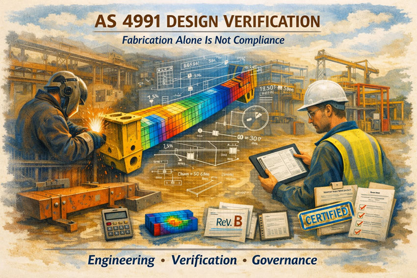
AS 4991 design verification process showing fabrication, engineering analysis and certification workflow.

Engineering Calculations That Donโ€™t Match the Fabrication

One of the most common issues is a disconnect between:

  • The engineered design intent
  • The shop drawings
  • The fabricated outcome

Changes made โ€œon the floorโ€ โ€” such as:

  • Plate thickness substitutions
  • Weld size adjustments
  • Lug geometry tweaks
  • Hole size changes

โ€” can invalidate the original engineering verification.

Without re-verification, certification becomes compromised.


Weld Design is Assumed โ€” Not Verified

Fabricators often focus on structural members but overlook:

  • Fillet weld capacity under combined loading
  • Fatigue considerations
  • Load directionality
  • Throat thickness assumptions

AS 4991 compliance requires welds to be engineered โ€” not assumed.

This is particularly critical in:

  • Spreaders
  • Lifting beams
  • Trunnions
  • Custom lifting frames

No Formal Design Review or Independent Check

The standard requires appropriate verification.

This may include:

  • Independent engineering review
  • Check calculations
  • Formal sign-off by a competent engineer

A workshop โ€œreviewing its own drawingsโ€ does not satisfy independent verification.


Load Cases Are Underestimated

Another common oversight is failure to account for:

  • Dynamic factors
  • Off-centre loading
  • Sling angles
  • Shock loading
  • Environmental factors

Lifting devices rarely operate under perfect static conditions.

Design verification must reflect real-world application.


Documentation Gaps

Even when the engineering is sound, documentation is often incomplete:

  • No clear calculation pack
  • No revision control
  • No traceable material certificates
  • No weld procedure documentation
  • No inspection and test plan

Without structured documentation, clients and auditors may reject otherwise adequate equipment.

This is where governance becomes as important as engineering.


Why This Matters

Failure in lifting devices carries:

  • Serious safety risk
  • Legal liability
  • Project shutdowns
  • Insurance exposure

Under Australian WHS law, the duty of care extends beyond fabrication โ€” it includes engineering adequacy.

AS 4991 is not a box-ticking exercise. It is a risk mitigation framework.


The Hamilton By Design Approach

At Hamilton By Design, we support fabricators by providing:

  • Independent design verification
  • Engineering calculation packages
  • Weld capacity review
  • Load case validation
  • Documentation structured for audit readiness
  • Revision-controlled drawing governance

We work alongside workshops โ€” not against them โ€” ensuring compliance before equipment reaches site.

The cost of early verification is small compared to rework, rejected certification, or liability exposure.


3D LiDAR scanning and 3D modelling service button โ€” laser scanner capturing a point cloud for engineering and CAD modelling
Mechanical engineering services

Final Thought

If your lifting device cannot withstand engineering scrutiny on paper, it should not be trusted in the air.

AS 4991 compliance is not about fabrication skill alone โ€” it is about verified engineering intent.

If you would like assistance reviewing your lifting device designs or establishing a verification framework, reach out to the Hamilton By Design team.


Name
Would you like us to arrange a phone consultation for you?
Address

3D CAD Modelling Australia service banner for Hamilton By Design
Finite Element Analysis (FEA) engineering simulation button
Mechanical engineering services

Bolts, Grades, Materials and Standards

A Practical Engineering Guide to Correct Fastener Selection in Australia

Bolts are one of the most common engineered components on any project โ€” and also one of the most misunderstood.

In drawings they appear as a simple note:
M16 โ€“ 8.8 โ€“ GALV

Yet behind that small call-out sits structural capacity, fatigue life, corrosion resistance, inspection compliance, and legal responsibility.

Many engineering failures do not occur because a beam was undersized or a calculation was incorrect.
They occur because the wrong fastener type was selected for the application.

This article explains:

  • Bolt and nut property classes
  • Where each class should be used
  • Carbon steel vs stainless steel
  • Coatings and environment suitability
  • Structural vs mechanical bolting
  • Australian Standards governing fasteners
  • How to review and challenge incorrect selections โ€” especially when mentoring graduate engineers

1. The Three Different Worlds of Bolting

Most confusion exists because people think a bolt is simply a stronger or weaker version of the same item.

In reality, bolts exist in three different engineering systems:

SystemPurposeGoverning Standards
General Mechanical FasteningHolding components togetherISO / AS 1110 / AS 4291
Structural BoltingLoad transfer between steel membersAS/NZS 1252 / AS 4100
Corrosion Resistant FasteningSurvive environmentStainless / coatings standards

Using a bolt from the wrong system often creates hidden failures.


2. Bolt Property Classes (Metric)

Metric bolts are marked with numbers such as 4.6, 8.8, 10.9, 12.9

These numbers define material strength.

What the Numbers Mean

First number โ†’ Ultimate tensile strength (ร—100 MPa)
Second number โ†’ Yield ratio

Example:

8.8 bolt
800 MPa tensile strength
Yields at 80% = 640 MPa


Typical Bolt Classes and Their Uses

ClassStrength LevelTypical Applications
4.6LowLight brackets, sheet metal
4.8Lowโ€“mediumGeneral hardware
5.8MediumAutomotive covers
6.8MediumMachinery guards
8.8High tensileGeneral engineering & structural connections
9.8Higher tensileAutomotive mechanical
10.9Very high tensileMining equipment, heavy plant
12.9Ultra high tensileTooling, precision machinery

Important Engineering Concept

A stronger bolt is not always better.

Higher strength bolts:

  • are less ductile
  • tolerate less misalignment
  • fatigue faster in bending

Many failures occur when 12.9 bolts are used where 8.8 bolts were intended.


3. Nut Property Classes

Nuts are graded differently.
They must match the bolt strength.

Nut ClassSuitable Bolt
44.6
55.8
66.8
88.8
99.8
1010.9
1212.9

Critical Rule

Nut class must be equal or higher than bolt class first number

If not, the joint will strip before correct preload is reached.


4. Carbon Steel vs Stainless Steel

Many installations choose stainless assuming it is โ€œbetterโ€.

It is not stronger โ€” it is more corrosion resistant.


Mechanical Comparison

PropertyHigh Tensile Carbon SteelStainless Steel
StrengthHighMedium
Fatigue resistanceGoodLower
Vibration resistanceGoodPoorer
Corrosion resistanceDepends on coatingExcellent
Galling riskVery lowHigh
Torque capacityHighLimited

Stainless Grades

GradeEquivalent StrengthTypical Use
A2-50~5.8General hardware
A2-70~7.0Outdoor equipment
A4-80~8.8 tensileMarine / chemical

Important

Stainless steel often fails in structural joints due to:

  • lower yield strength
  • thread galling
  • relaxation under load

5. Coatings and Environment Suitability

Carbon steel requires corrosion protection.

CoatingEnvironment
Black oxideIndoor machinery
Zinc platedIndoor dry
Zinc passivateWorkshop conditions
Hot dip galvanisedOutdoor structural
Mechanical galvanisedStructural bolting
Dacromet / GeometMining & heavy corrosion

Engineering Impact of Coatings

Coatings change friction.

Friction changes preload.

Therefore torque charts must match coating type.

Incorrect torque values are one of the most common installation errors.


6. Structural Bolting vs Mechanical Bolting

These must never be confused.

Mechanical Bolting

Purpose: hold parts together

Failure mode: loosening

Structural Bolting

Purpose: transfer load through friction or bearing

Failure mode: structural collapse

Structural bolts require:

  • certified assemblies
  • controlled tightening method
  • inspection records

General hardware bolts must never be substituted.


7. Storage and Handling Requirements

Fasteners can degrade before use.

Problems Caused by Poor Storage

  • Coating breakdown
  • Hydrogen embrittlement risk
  • Rust under galvanising
  • Lost certification traceability
  • Incorrect torque performance

Recommended Storage Practices

Environment

Dry
Covered
Off concrete
Stable temperature

Handling

Keep manufacturer packaging
Do not mix batches
Record heat numbers

Stainless Steel

Must be isolated from carbon steel contamination.

Carbon particles embed โ†’ rust later appears


8. Australian Standards for Fasteners

Below is a consolidated list relevant to Australian engineering practice.


Mechanical Properties

AS/NZS 4291.1 โ€” Mechanical properties of bolts, screws and studs
AS/NZS 4291.2 โ€” Mechanical properties of nuts
ISO 898-1 / ISO 898-2 โ€” Referenced strength properties
ISO 3506 โ€” Stainless steel fasteners


Dimensions & Threads

AS 1110 โ€” Metric hex bolts & screws
AS 1111 โ€” Metric fasteners
AS 1112 โ€” Hexagon nuts
AS 1275 โ€” Metric screw threads
AS 1721 โ€” General purpose metric threads


Structural Bolting

AS/NZS 1252 โ€” High strength structural bolting assemblies
AS 4100 โ€” Steel structures design
AS/NZS 5131 โ€” Structural steel fabrication & erection


3D LiDAR scanning and 3D modelling service button โ€” laser scanner capturing a point cloud for engineering and CAD modelling
Mechanical engineering services

Corrosion Protection

AS/NZS 1214 โ€” Galvanised coatings on threaded fasteners
AS/NZS 4680 โ€” Hot dip galvanising
AS 2312.2 โ€” Corrosion protection guide
AS 1897 โ€” Electroplated coatings


Locking and Reliability

AS 4145.2 โ€” Locking devices for fasteners


9. Mentoring the Graduate Engineer

What To Do When the Selection Is Wrong

One of the responsibilities of senior engineers is not just checking work โ€” but teaching judgement.

A graduate will often select bolts by:

  • copying an old drawing
  • choosing stainless for safety
  • choosing highest strength available
  • assuming galvanised means structural

Rather than correcting immediately, guide the reasoning.


Questions That Help Them Learn

Instead of saying โ€œthat is wrongโ€, ask:

What load path is the bolt carrying?
Is it clamping, locating, or supporting?

What failure mode are we preventing?
Slip, fatigue, shear, corrosion, loosening?

Is the environment or the force governing selection?

Does the standard require a certified assembly?

What inspection method applies?


The Goal

Teach that engineering is not selecting a stronger component โ€”
it is selecting the correct component for the failure mode.


Hamilton By Design logo displayed on a blue tilted rectangle with a grey gradient background

Conclusion

Fasteners are engineered components.

Correct selection depends on understanding:

  • strength class
  • application type
  • environment
  • installation method
  • applicable standards

Most bolted joint failures occur not from calculation error, but from incorrect assumptions about what the bolt is meant to do.

Engineering quality is achieved when design intent matches real behaviour.

Name
Would you like us to arrange a phone consultation for you?
Address
3D CAD Modelling Australia service banner for Hamilton By Design
Finite Element Analysis (FEA) engineering simulation button
Mechanical engineering services

Engineering Drafting Services on the Central Coast

Engineer and client conducting site scanning near Central Coast Stadium in Gosford

Engineering Drafting Services Central Coast NSW | Hamilton By Design

When engineering projects move from concept to construction, clear and accurate drawings are what make the difference between smooth delivery and costly rework. For businesses on the Central Coast, having access to reliable, local engineering drafting services means faster communication, better outcomes, and drawings that actually work on site.

Hamilton By Design, based on the NSW Central Coast, provides professional engineering drafting services to support mechanical, structural, and industrial projects across the region and beyond.


Engineer using LiDAR scanner with client at Gosford Foreshore, Central Coast Stadium and Brisbane Water in background

What Are Engineering Drafting Services?

Engineering drafting is the process of converting design concepts, engineering calculations, and site requirements into detailed technical drawings. These drawings are used by fabricators, machinists, builders, and installers to manufacture and construct components correctly the first time.

Our drafting services typically include:

  • Dimensioned manufacturing drawings
  • Assembly and exploded views
  • Welded fabrication drawings
  • Structural steel and connection details
  • General arrangement (GA) drawings
  • Site and installation layouts

Clear drafting ensures everyone involved in the project is working from the same, accurate information.

Supporting Central Coast Industry & Construction

The Central Coast is home to a wide range of industries, including manufacturing, construction, infrastructure maintenance, and industrial services. We regularly support local businesses, contractors, and engineers who need drafting work completed accurately and efficiently.

Being locally based means we understand:

  • regional fabrication capabilities
  • site access and installation constraints
  • Australian Standards and compliance requirements
  • the importance of practical, buildable solutions

When needed, we can work closely with clients, fabricators, and installers to make sure drawings reflect real-world conditions.

3D LiDAR scanning services on the Central Coast providing engineering-grade laser scanning, point cloud capture, scan-to-CAD modelling and industrial reality capture for infrastructure and industrial projects.
Drafting services on the Central Coast providing engineering drawings, fabrication detailing, as-built documentation, reverse engineering and CAD drafting for industrial and infrastructure projects.
Mechanical engineering services on the Central Coast providing industrial design, plant inspections, pump calculations, reverse engineering and engineering support for manufacturing, infrastructure and heavy industry projects.

Our Engineering Drafting Capabilities

We provide engineering drafting using SolidWorks and proven industry workflows.

Mechanical Drafting

  • Machined component drawings
  • Sheet metal and folded parts
  • Assemblies with bills of materials (BOMs)
  • Practical tolerancing for manufacturing

Structural & Fabrication Drafting

  • Structural steel and fabrication drawings
  • Weld symbols and fabrication notes
  • Platforms, handrails, and access systems
  • Workshop-ready drawing packs

As-Built & Legacy Drawing Updates

  • As-built drawings for existing assets
  • Updating and converting legacy drawings
  • Reverse engineering from physical components

Who We Work With

Our Central Coast engineering drafting services support:

  • manufacturers and machine shops
  • builders and fabricators
  • mining and industrial contractors
  • engineering consultants
  • councils and asset owners

From one-off components to ongoing drafting support, we scale our services to suit your project.

Why Choose a Local Engineering Drafting Service?

Working with a Central Coastโ€“based drafting provider offers real advantages:

  • easier communication and faster turnaround
  • understanding of local suppliers and trades
  • drawings created with fabrication and installation in mind
  • long-term support for updates and modifications

At Hamilton By Design, our drafting work is backed by hands-on engineering and manufacturing experience โ€” not just CAD skills.


Hamilton By Design logo displayed on a blue tilted rectangle with a grey gradient background
3D LiDAR scanning and 3D modelling service button โ€” laser scanner capturing a point cloud for engineering and CAD modelling
Mechanical engineering services

Engineering Drafting You Can Build From

If youโ€™re looking for engineering drafting services on the Central Coast that deliver clear, practical, and construction-ready drawings, Hamilton By Design can help.

Get in touch to discuss your project or request a quote.


Name
Would you like us to arrange a phone consultation for you?
Address


Finite Element Analysis (FEA) engineering simulation button
Mechanical engineering services