Across Australia’s forestry, sawmill and timber processing industries, industrial infrastructure continues to evolve through ongoing maintenance, shutdown upgrades, plant expansions and operational modifications. Conveyor systems are extended, timber transfer systems are upgraded, structural steel platforms are altered, machinery is relocated and new processing equipment is integrated into ageing brownfield facilities that may have operated continuously for decades.
While many of these changes are often completed to improve productivity or maintain operational continuity, one of the greatest hidden risks within industrial environments is modifying or designing plant equipment without proper engineering review, engineering governance and qualified engineering sign-off.
In many industrial workplaces, practical trade experience is highly respected — and rightly so. Skilled tradespeople are essential to fabrication, installation, shutdown works, plant maintenance and operational reliability. However, building something that functions mechanically is not the same as engineering a system that is safe, compliant, reliable and suitable for long-term industrial operation.
This distinction becomes critically important in industries such as forestry, logging and timber processing where machinery regularly handles heavy loads, rotating equipment, moving conveyors, unstable timber products, stored energy and high-throughput material handling systems.
Across sawmills and timber processing facilities throughout Australia, industrial systems are exposed to continuous operational stresses involving vibration, shock loading, impact forces, moisture, abrasive materials, dust contamination and changing environmental conditions. Conveyor systems, debarkers, screw augers, bucket elevators, log transfer systems and structural platforms must all operate safely while supporting continuous production under demanding industrial conditions.

Without proper engineering consideration, even seemingly simple modifications can introduce serious risk.
Over the past several decades, Australian workplace regulators and courts have repeatedly prosecuted companies following incidents involving timber handling systems, conveyors, rotating shafts, sawmill machinery and plant modifications that failed to adequately consider engineering safety requirements.
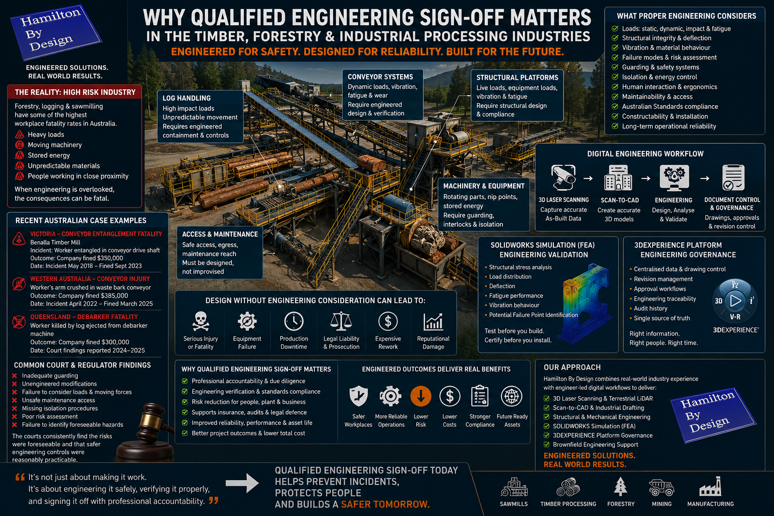
In one Victorian timber mill incident, a worker died after becoming entangled in a conveyor drive shaft. WorkSafe Victoria later found that engineering controls and guarding solutions were reasonably practicable and could have prevented the fatality. In Western Australia, a timber processing company was fined after a worker suffered catastrophic arm injuries involving inadequately guarded conveyor equipment. In Queensland, a timber company faced prosecution after a worker was killed by a log ejected from a debarker machine.
Although each incident involved different operational circumstances, the underlying engineering failures followed remarkably similar patterns:
- inadequate guarding,
- unengineered plant modifications,
- failure to consider loads and moving forces,
- unsafe maintenance access,
- missing isolation procedures,
- poor risk assessment,
- insufficient structural verification,
- lack of engineering review,
- and failure to identify foreseeable operational hazards.
These are engineering failures — not simply fabrication problems.
A tradesperson may know how to weld, fabricate, cut or assemble industrial equipment, but engineering requires a much deeper understanding of how systems behave under operational conditions over time.
Proper engineering design must consider:
- static and dynamic loading,
- fatigue and cyclic stresses,
- vibration,
- structural deflection,
- torque and rotational forces,
- impact loading,
- material behaviour,
- wear characteristics,
- human interaction with machinery,
- guarding requirements,
- maintainability,
- failure modes,
- constructability,
- Australian Standards compliance,
- and long-term operational reliability.
This is why qualified engineering sign-off matters.
Engineering sign-off is not simply a signature placed on a drawing. It represents professional accountability that the design has been reviewed, assessed and verified against engineering principles, foreseeable operational conditions and applicable standards.
Without proper engineering oversight, industrial businesses expose themselves to major commercial, operational and legal risk.
Poorly engineered modifications can lead to:
- worker injury or fatalities,
- structural failure,
- conveyor collapse,
- equipment damage,
- production downtime,
- voided insurance claims,
- failed audits,
- regulatory prosecution,
- expensive shutdown rework,
- project delays,
- and reputational damage.
In many industrial facilities, the risk develops gradually over time. Equipment modifications are often completed during shutdowns or urgent maintenance periods where production pressure overrides long-term engineering review. Small undocumented changes accumulate over years until facilities no longer reflect their original engineered design intent.
Drawings become outdated.
Loads change.
Access paths are altered.
Equipment is relocated.
Platforms are modified.
Conveyors are extended.
Additional services are added.
Over time, facilities can drift significantly away from their original engineered condition.
This is where engineering governance becomes critically important.
At Hamilton By Design, we are an engineer-led organisation focused on delivering engineered outcomes rather than simply trade-based solutions.
While practical trade experience remains essential within industrial environments, our approach extends beyond fabrication and installation alone. We apply engineering thinking, digital engineering workflows and industrial experience to support long-term operational reliability, constructability and risk reduction.
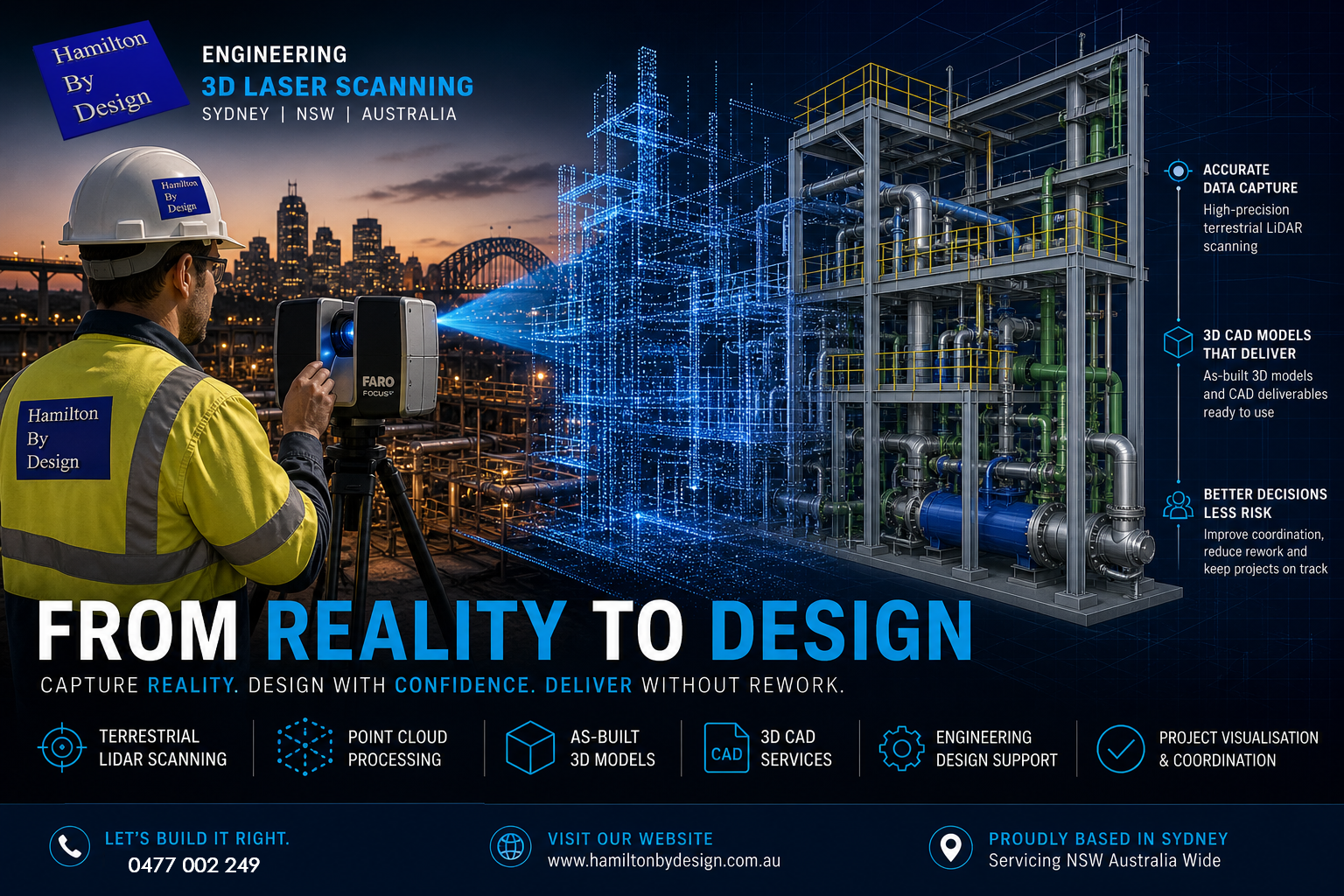
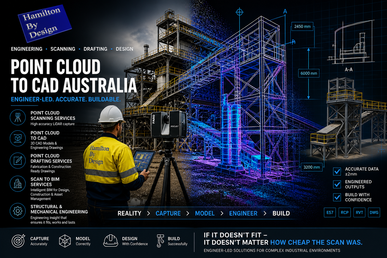
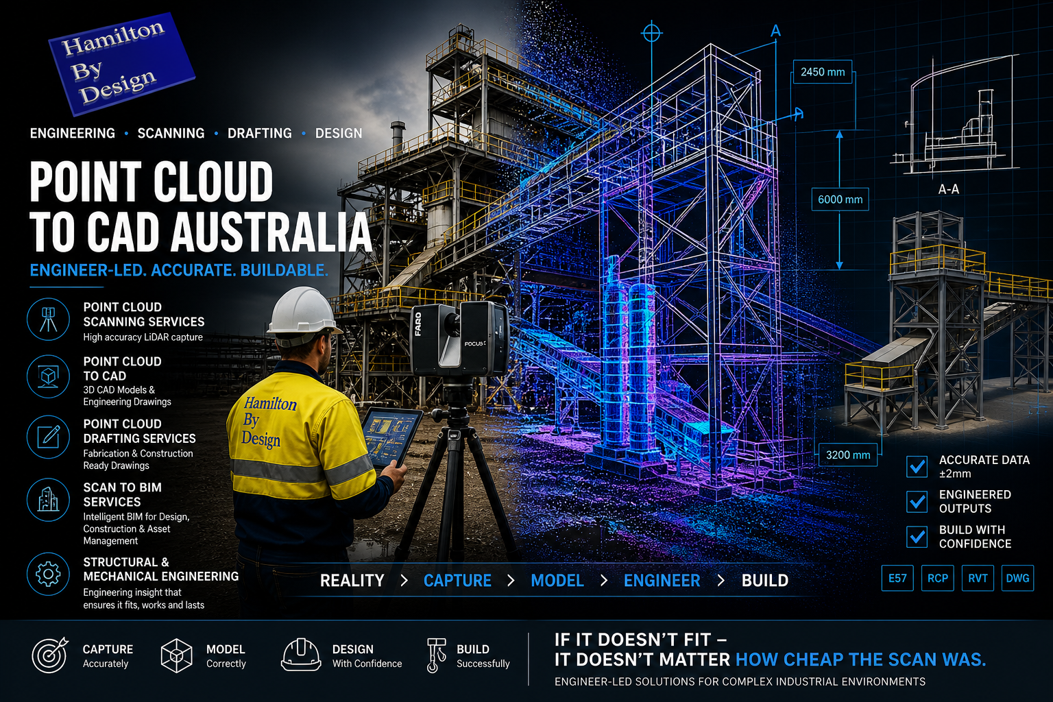
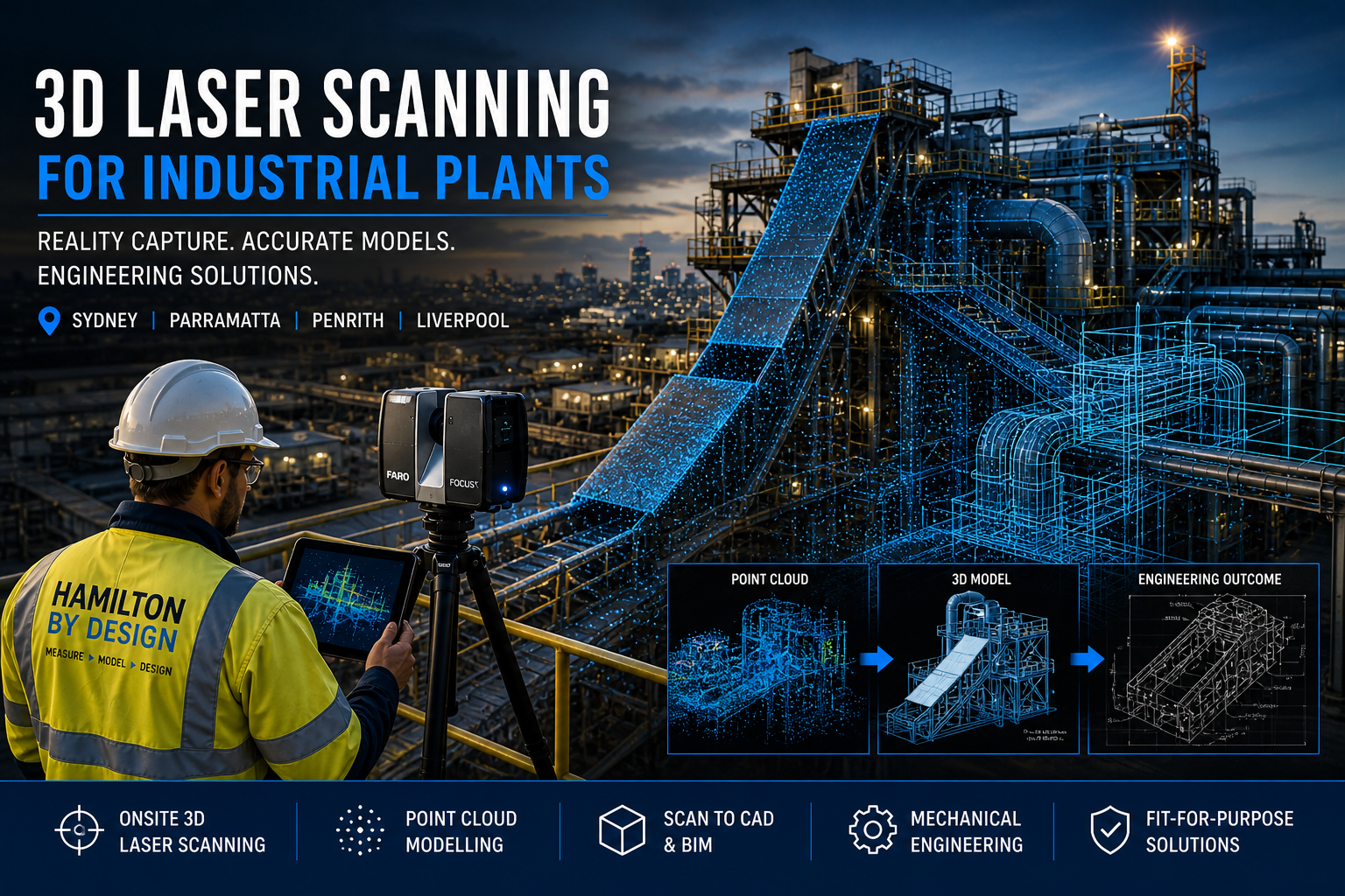
Using engineering-grade 3D laser scanning, terrestrial LiDAR capture and scan-to-CAD workflows, we help industrial clients establish accurate as-built conditions before design or fabrication work begins.
Rather than relying on outdated PDFs or manual measurements, project teams gain access to highly accurate point cloud data that reflects real-world plant conditions. This allows engineers, fabricators and project managers to identify operational risks earlier and improve confidence before fabrication or construction begins.
Engineering-grade point clouds can then be converted into detailed CAD models suitable for:
- structural analysis,
- equipment integration,
- plant upgrades,
- fabrication detailing,
- conveyor layouts,
- clash detection,
- and engineering verification.
One of the major advantages of modern digital engineering workflows is the ability to perform engineering validation before equipment is manufactured or installed onsite.
Using SOLIDWORKS Simulation and Finite Element Analysis (FEA), industrial components and structures can be digitally tested under operational loading conditions to assess how equipment may behave before fabrication occurs.
FEA allows engineers to evaluate:
- structural stress,
- deflection,
- load distribution,
- fatigue performance,
- vibration behaviour,
- and potential failure points.
This becomes particularly valuable within forestry and timber processing facilities where conveyor systems, transfer structures, platforms and machinery supports are exposed to continuous operational loading and vibration.
Rather than relying on assumptions or “rule of thumb” workshop modifications, FEA allows engineering decisions to be supported by measurable analysis and engineering verification.
This significantly improves confidence in the design process while helping reduce the risk of structural failure, overloading or premature wear.
At Hamilton By Design, digital engineering workflows can also be supported through the 3DEXPERIENCE platform, providing engineering governance and controlled management of industrial drawing systems and project information.
Modern industrial projects increasingly require:
- revision control,
- controlled approvals,
- drawing issue states,
- engineering traceability,
- audit history,
- and a single source of truth across multiple project stakeholders.
The 3DEXPERIENCE platform supports this by allowing controlled management of CAD models, drawings, revisions and engineering workflows within a centralised digital environment.
This provides significant advantages for industrial and brownfield projects where multiple contractors, engineers, fabricators and maintenance teams may all be interacting with the same plant infrastructure over long operational lifecycles.
Engineering governance through structured drawing control helps ensure:
- approved drawings remain current,
- revision history is traceable,
- superseded drawings are controlled,
- engineering changes are documented,
- and project teams are working from reliable information.
In industries such as forestry, timber processing, mining and manufacturing, poor drawing control can create major operational and safety risks if outdated or unverified information is used during fabrication or construction activities.
At Hamilton By Design, our workflows focus on engineering-grade deliverables designed to support practical industrial outcomes.
This includes:
- engineering-grade 3D laser scanning,
- terrestrial LiDAR capture,
- scan-to-CAD workflows,
- industrial drafting,
- structural and mechanical modelling,
- FEA-supported engineering workflows,
- revision-controlled drawing systems,
- and brownfield engineering support.


We do not simply create geometry or visualisation models.
We focus on engineering workflows designed to support real-world industrial reliability, constructability and operational performance.
Because in high-risk industrial environments, “it works” is not the same as “it has been engineered safely.”

Qualified engineering sign-off matters because the consequences of poor engineering decisions can extend far beyond production downtime — affecting worker safety, operational reliability, legal liability and the long-term success of industrial infrastructure.
If your business is seeking engineered outcomes that outlast short-term fixes, Hamilton By Design provides engineer-led digital engineering support designed to help reduce risk and engineer success across industrial operations throughout Australia.