Engineering Governance with 24/7 Drawing Access & Advanced FEA | Hamilton By Design
Australian manufacturing does not stop at 5pm.
Projects run across time zones.
Procurement decisions happen after hours.
Site teams need answers immediately.
Your engineering data must be available when your business needs it — not when someone is back in the office.
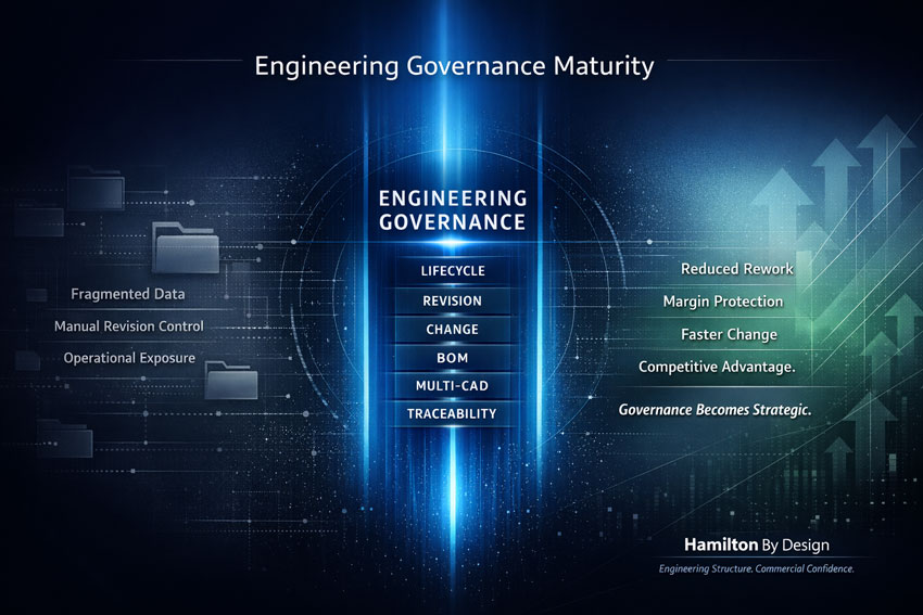
At Hamilton By Design, we provide structured engineering governance with secure 24 hours, 7 days a week access to your drawings, controlled revision management, protected design data, and advanced engineering analysis capability.
24/7 Access to Released Engineering Data
Engineering delays often occur for one simple reason:
The right drawing cannot be found.
Or worse — the wrong revision is used.
We help organisations implement structured digital environments where:
✔ Released drawings are accessible anytime
✔ Models and documentation are securely stored
✔ Teams work from a single source of truth
✔ Permissions control who can edit and who can view
✔ Data is protected but accessible
Whether your team is in the office, on site, or working remotely, access to correct engineering information becomes immediate and controlled.
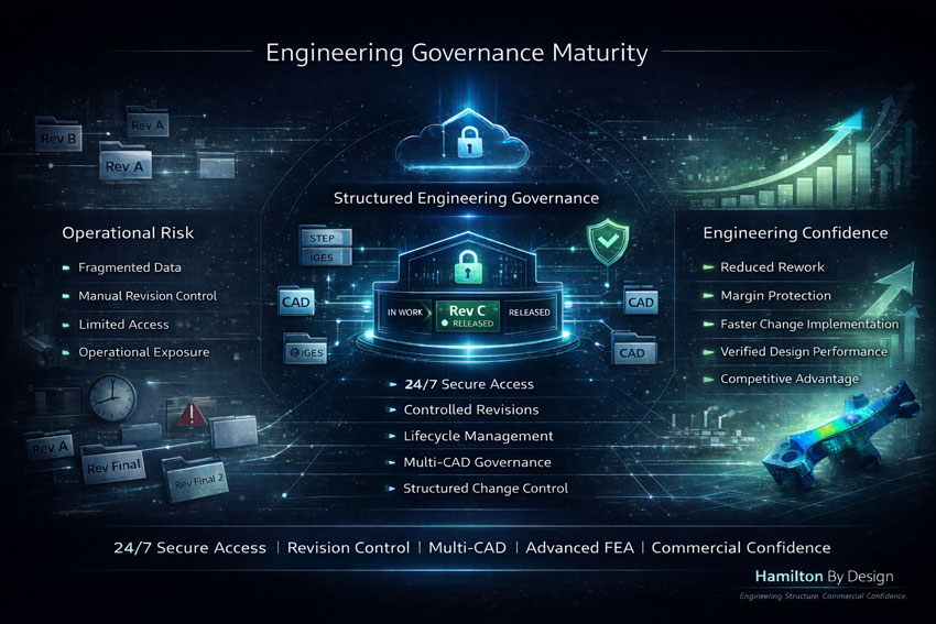
Structured Revision Control & Lifecycle Discipline
Revision control is not administrative — it is commercial risk management.
Without structured governance:
- Manufacturing builds from outdated drawings
- Procurement orders to superseded revisions
- Change approvals are undocumented
- Accountability becomes unclear
Hamilton By Design assists in implementing disciplined lifecycle management including:
• Controlled revision numbering
• Defined lifecycle states (In Work → Released → Superseded)
• Formal change review and approval workflows
• Complete traceability of design decisions
• Audit-ready documentation
This ensures that engineering change becomes structured and predictable — not reactive.
Design Data Governance Across Multi-CAD Environments
Modern manufacturers operate in complex digital ecosystems.
You may be working with:
- Native mechanical CAD
- 2D drawings
- Neutral formats such as STEP
- Supplier-generated geometry
- Legacy data
- Scan-to-CAD models
We support governance across multiple CAD platforms, ensuring:
✔ Data consistency
✔ Controlled release processes
✔ Alignment between drawings and Bills of Materials
✔ Protection of intellectual property
✔ Reduced duplication and confusion
Engineering governance must extend across all formats — not just one system.
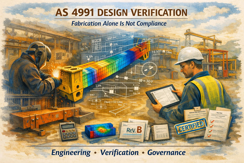
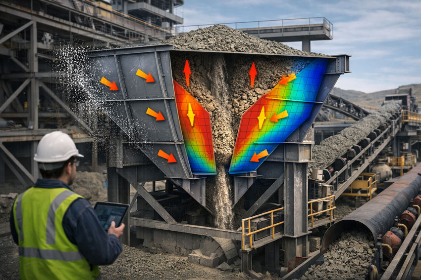
Advanced FEA Tools for Engineering Confidence
Governance alone is not enough.
Engineering strength must be validated.
Hamilton By Design integrates advanced Finite Element Analysis (FEA) tools into structured engineering workflows, allowing:
- Structural validation of components
- Load case analysis
- Stress and deflection verification
- Design optimisation
- Risk reduction prior to manufacture
By combining disciplined data control with engineering-grade analysis, decisions are made with confidence — not assumption.
FEA becomes part of a controlled, traceable design process.
From Data Control to Commercial Confidence
When engineering governance, revision control, and advanced analysis are aligned:
✔ Rework reduces
✔ Margins are protected
✔ Change is implemented faster
✔ Compliance improves
✔ Teams work with clarity
✔ Directors gain visibility
This is how Australian manufacturers remain competitive in a high-cost environment.


Engineering Structure. Commercial Confidence.
Hamilton By Design does not simply provide engineering services.
We help organisations level up their engineering maturity by combining:
- 24/7 secure access to drawings
- Structured revision control
- Multi-CAD governance
- Integrated design data management
- Advanced FEA capability
The result is a disciplined engineering environment that supports growth, protects margin, and reduces operational exposure.
If your engineering data still lives in shared drives and spreadsheets, it may be time to move toward structured governance.
Hamilton By Design — Engineering Structure. Commercial Confidence.


Mechanical Engineering | Structural Engineering