High Court Changes Engineering Liability

Split-screen engineering graphic comparing assumed as-built drawings with verified point cloud scanning data, highlighting the difference between estimated geometry and measured reality.

The High Court Just Changed Engineering Liability โ€” Why โ€œAs-Built Guessingโ€ Is No Longer Enough

The recent High Court decision in Pafburn Pty Ltd v The Owners โ€“ Strata Plan No 84674 has been widely discussed across the construction and legal sectors. Most commentary has focused on developers and builders, particularly the finding that they can be held fully liable for defects and cannot rely on proportionate liability to distribute responsibility.

But for engineers, designers, and anyone working in brownfield environments, the real impact runs deeper.

This case signals a clear shift in expectation โ€” away from assumption, and toward verified reality.


3D LiDAR scanning and 3D modelling service button โ€” laser scanner capturing a point cloud for engineering and CAD modelling
Mechanical engineering services

The Hidden Risk in โ€œAs-Builtโ€ Drawings

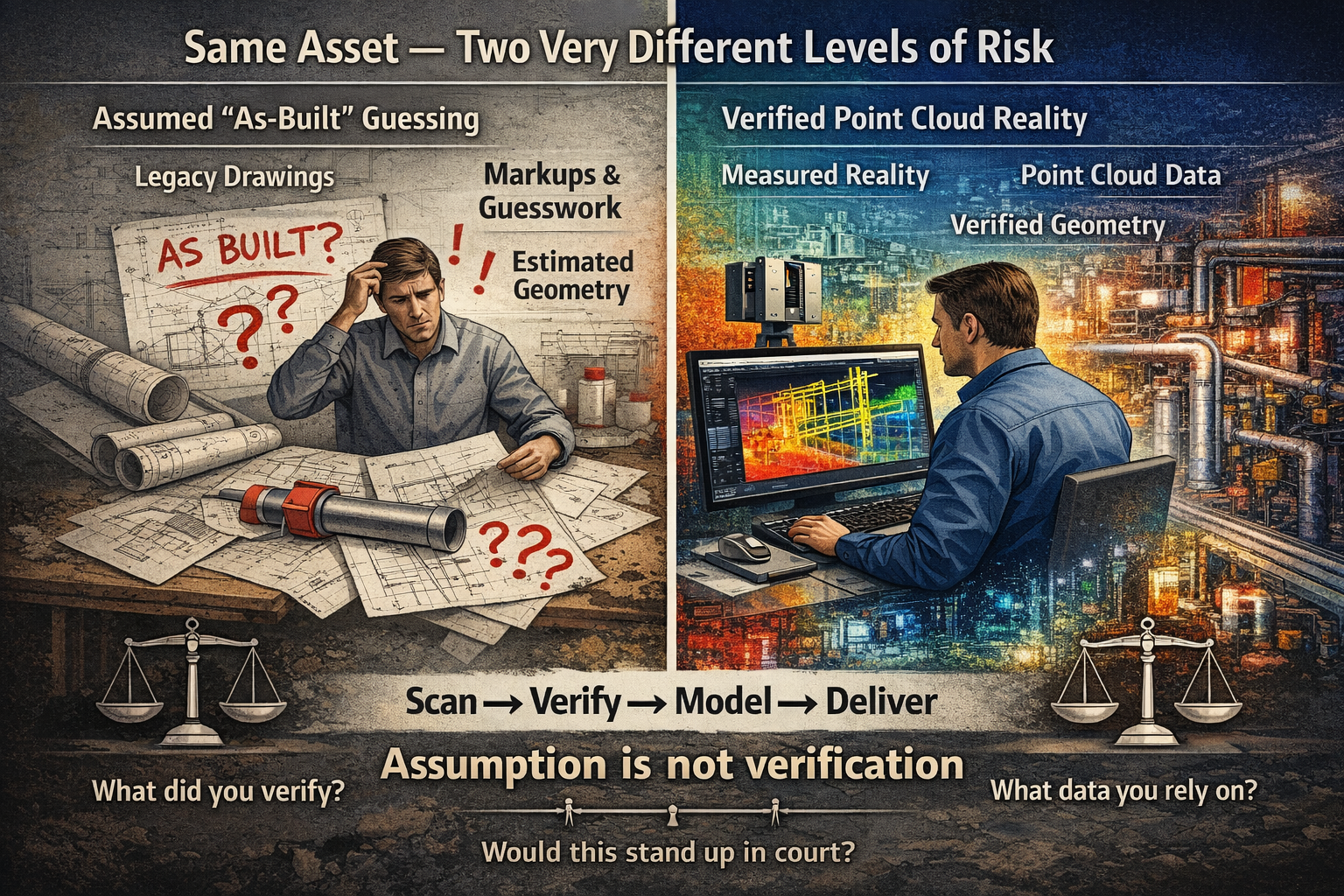
Across many projects, particularly in retrofit, maintenance, and upgrade work, design offices rely on what are commonly referred to as โ€œas-builtโ€ drawings.

In theory, these drawings represent what has actually been constructed on site.

In practice, however, that is not always the case.

Many โ€œas-builtsโ€ are produced through:

  • Manual markups during construction
  • Redline drawings updated after installation
  • Verbal confirmation from site teams
  • Interpretation of incomplete or outdated information

In some cases, they are never formally verified at all.

This creates a fundamental problem.

The design office is making decisions based on information that may be:

  • Incomplete
  • Inaccurate
  • Or in the worst case โ€” assumed

The Question That Is Now Being Asked

Following this High Court decision, the legal environment is changing.

It is no longer sufficient to say:

โ€œI worked from the drawings provided.โ€

Instead, the question is becoming:

What should a competent engineer have verified?

This is a significant shift.

It places responsibility not just on what information was used โ€” but on whether that information should have been trusted in the first place.


Assumption vs Measured Reality

At its core, this issue comes down to a simple comparison:

Does guessing what has been built offer the same level of coverage as measured data?

The answer is increasingly clear โ€” it does not.

When geometry is assumed:

  • Tolerances are unknown
  • Deviations from design are hidden
  • Errors compound as projects progress
  • Rework risk increases

More importantly, from a legal standpoint:

There is no defensible evidence of what actually existed at the time decisions were made.


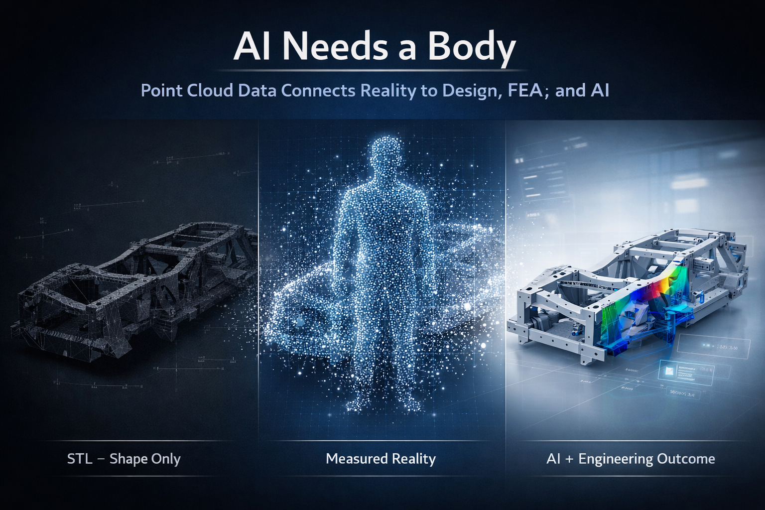
The Role of Point Cloud Scanning

This is where point cloud scanning and reality capture fundamentally change the workflow.

Rather than relying on interpretation, point cloud data provides a direct measurement of site conditions.

A properly captured scan:

  • Records millions of measured points across the asset
  • Captures geometry exactly as installed
  • Provides a timestamped dataset of site conditions
  • Can be referenced, rechecked, and validated at any time

Most importantly, it creates a feedback loop between site and design.

Instead of guessing what has been built, the design office receives:

  • Accurate geometry
  • Verified spatial relationships
  • Real-world constraints

This allows models and drawings to be developed based on reality, not assumption.


Feeding Reality Back Into the Design Office

One of the most overlooked issues in engineering workflows is the disconnect between site and design.

Information typically flows in one direction:

  • Design โ†’ Construction

But the return flow:

  • Construction โ†’ Design

Is often inconsistent or incomplete.

Point cloud scanning closes this gap.

By scanning installed conditions and feeding that data back into the design environment, engineers can:

  • Align models with actual site geometry
  • Identify clashes before fabrication or installation
  • Validate clearances and fitment
  • Reduce the risk of downstream errors

This is not just about accuracy โ€” it is about confidence.


Why This Matters More After the High Court Decision

The implications of Pafburn Pty Ltd v The Owners โ€“ Strata Plan No 84674 go beyond contractual structures.

They influence how engineering decisions are evaluated.

When something goes wrong, the question is no longer simply:

โ€œWho was responsible for the design?โ€

It becomes:

  • What information was relied upon?
  • Was it reasonable to rely on that information?
  • Could the actual conditions have been verified?

If the tools to verify existed โ€” and were not used โ€” that becomes part of the discussion.


From Design Intent to Verified Condition

The industry is moving through a transition.

Historically, projects were driven by:

  • Design intent
  • Nominal dimensions
  • Idealised geometry

Today, the expectation is shifting toward:

  • Verified condition
  • Measured data
  • Real-world constraints

This shift is particularly important in:

  • Brownfield upgrades
  • Industrial plants
  • Mining infrastructure
  • Retrofit and modification projects

Where existing conditions rarely match original design documentation.


Practical Implications for Engineers

For engineers and designers, this means a change in approach.

Relying solely on drawings โ€” particularly for existing assets โ€” introduces risk.

A more robust workflow includes:

  • Verification of critical geometry
  • Clear documentation of data sources
  • Separation of assumed vs measured information
  • Use of reality capture where accuracy matters

This is not about replacing engineering judgement.

It is about supporting that judgement with evidence.


Conclusion: Coverage, Confidence, and Accountability

At the centre of this discussion is a simple idea:

Not all information offers the same level of coverage.

โ€œAs-builtโ€ drawings based on interpretation provide one level of confidence.

Measured point cloud data provides another.

As legal expectations evolve, the difference between the two becomes more significant.

Guessing what has been built โ€” even when done carefully โ€” does not offer the same level of coverage as data that can be measured, verified, and defended.


How We Approach It

At Hamilton By Design, our workflow is built around this principle:

Scan โ†’ Verify โ†’ Model โ†’ Deliver

By capturing real-world conditions and feeding that data back into the design process, we reduce uncertainty and provide a clear basis for engineering decisions.

Not just for better outcomes โ€” but for greater accountability.


If your next project relies on โ€œas-builtโ€ drawings alone, it is worth asking:

Are they measuredโ€ฆ or assumed?

3D CAD Modelling Australia service banner for Hamilton By Design

Our clients

AI Needs a Body โ€“ Why Point Cloud Data Powers the Next Generation of Engineering

AI needs a body concept showing STL mesh, point cloud data, and CAD model with FEA for engineering workflow

Engineering is entering a new phase.

Artificial intelligence is being integrated into design platforms, automation is accelerating workflows, and digital engineering environments are becoming more connected than ever before. Tools such as SolidWorks are now introducing AI assistants like AURA, LEO, and Marie, promising smarter design, faster modelling, and improved decision-making.

But there is a fundamental issue that is often overlooked:

AI cannot design, validate, or optimise anything without a physical reference.

AI needs a body.

And in engineering, that body is real-world, measurable data.

3D point cloud scanning provides that foundation.


3D LiDAR scanning and 3D modelling service button โ€” laser scanner capturing a point cloud for engineering and CAD modelling
Mechanical engineering services

Gen 1, Gen 2, Gen 3 โ€“ The Evolution of Engineering

Engineering workflows can be broadly understood in three stages: Gen 1, Gen 2, and Gen 3.

Gen 1 was manual. Tape measures, site sketches, and experience-driven decisions formed the basis of design. While effective for its time, it relied heavily on interpretation and often resulted in rework due to incomplete data.

Gen 2 introduced CAD platforms such as SolidWorks, Autodesk Inventor, Autodesk Fusion, and Onshape. This enabled parametric modelling, faster iteration, and improved documentation. However, Gen 2 introduced a new problemโ€”designs were often disconnected from reality. Models were built based on assumptions, outdated drawings, or incomplete site data.

Even when scanning was introduced, the workflow often stopped at STL or OBJ files. These formats are visual representations only. They are static, faceted, and lack the structure required for engineering.

Gen 3 represents the shift to reality-based engineering. This is where point cloud scanning, CAD, FEA, AI, and lifecycle management systems all connect. The key difference is that models are no longer based on assumptionsโ€”they are derived from measured reality.


The Problem With STL Workflows

STL files are commonly produced by handheld or metrology-grade scanners. They are easy to generate and provide a visually accurate representation of a component.

However, an STL file is a triangulated mesh. It contains no features, no relationships, and no design intent. It is a surface approximation made up of flat facets.

This creates a major limitation.

An STL file can show what something looks like, but it cannot define how it functions, how it should be modified, or how it should be manufactured.


Why FEA on STL Is Not Best Practice

It is technically possible to run Finite Element Analysis (FEA) on an STL file, but it is not considered best practice.

The reasons are straightforward.

The geometry is not true. Surfaces are faceted, holes are not perfect circles, and edges are broken into triangles. This makes it difficult to apply loads and boundary conditions accurately.

Because the STL is already a mesh, FEA introduces a second mesh on top of it. This reduces control over element quality and can affect convergence and accuracy.

Most importantly, the results are based on an approximation rather than engineered geometry.

You are analysing a surface representation, not a design.

For engineering decisions, this creates risk. Results become difficult to verify, defend, or repeat.


AI Has the Same Limitation

AI assistants such as AURA, LEO, and Marie are designed to work inside CAD environments. They rely on structured, parametric data to assist with modelling, optimisation, and decision-making.

They are highly effective when working with:

  • Defined features
  • Parametric relationships
  • Clean geometry

But when given an STL file, AI faces the same problem as the engineer.

There are no features to interpret, no constraints to follow, and no design intent to understand. The data is simply a collection of triangles.

As a result:

AI cannot meaningfully design or optimise from an STL file.

It can attempt to approximate geometry, but it cannot guarantee accuracy, intent, or engineering reliability.


AI Needs a Body

AI is often described as the brain of the future engineering workflow.

But a brain alone is not enough.

Without a body:

  • There is no spatial context
  • No physical reference
  • No connection to reality

In engineering, the body is the physical asset captured in digital form.

This is where point cloud scanning becomes critical.


Point Cloud โ€“ The Body for Engineering and AI

Point cloud data captures millions of measured points in three-dimensional space. Each point represents a real-world coordinate.

This provides:

  • True geometry
  • Accurate spatial relationships
  • Complete environmental context

Unlike STL files, point clouds are not simplified or interpreted. They represent measured reality.

From this data, engineers can:

  • Extract accurate dimensions
  • Fit planes, cylinders, and features
  • Build parametric CAD models
  • Maintain traceability back to the original scan

This creates a reliable foundation for both engineering and AI.


The Correct Engineering Workflow

A robust, engineering-grade workflow follows a clear sequence:

Scan โ†’ Point Cloud โ†’ CAD Model โ†’ FEA โ†’ AI โ†’ Engineering Outcome

Each step adds value.

The scan captures reality.
The point cloud preserves it.
The CAD model structures it.
FEA validates it.
AI enhances it.

Without the point cloud, the entire process loses its connection to reality.


Vehicle Chassis Example

Consider the development or modification of a vehicle chassis.

Using an STL-based workflow, the process typically involves rebuilding geometry from a mesh, applying FEA to an approximation, and attempting to optimise the design without a reliable reference. This introduces risk in alignment, load paths, and final fitment.

Using a point cloud-based workflow, the chassis is scanned and modelled directly from measured data. FEA is applied to true geometry, and AI tools such as AURA, LEO, and Marie can assist in refining and optimising the design.

The result is accurate, repeatable, and ready for manufacturing.


Digital Twin, PLM, and the 3D Environment

Point cloud data also supports broader engineering systems, including Digital Mock-Up (DMU), Product Data Management (PDM), and Product Lifecycle Management (PLM).

These systems rely on a single source of truth.

Point cloud data provides that truth by ensuring alignment between the digital model and the physical asset.

This enables:

  • Lifecycle tracking
  • Design validation
  • Ongoing updates and modifications

It also supports Digital Twin environments, where the physical and digital worlds remain connected over time.


Manufacturing in Australia

For manufacturing, accuracy is critical.

Point cloud-driven workflows ensure that:

  • Components fit as intended
  • Drawings reflect real-world conditions
  • Rework is minimised
  • Fabrication is efficient

This is particularly important for local manufacturing in Australia, where precision and reliability directly impact cost and delivery.


The Bottom Line

It is not best practice to run FEA on an STL file. It is not effective to design from an STL file. And it is unrealistic to expect AI to compensate for poor input data.

STL files provide a visual reference, but they do not provide a foundation for engineering.

AI is a powerful tool, but it cannot operate without accurate, structured data.

AI cannot fix a workflow that starts with the wrong data.


Final Thought

Engineering is evolving.

Gen 1 was manual.
Gen 2 was digital.
Gen 3 is reality-based and AI-assisted.

AI is not the starting point. Data is.

And in modern engineering:

AI needs a body.
Point cloud scanning is that body.

Our Clients

Finite Element Analysis (FEA) engineering simulation button
Mechanical engineering services

Why Point Cloud Data Beats STL for Real Engineering Work

Point cloud to CAD workflow showing transition from STL mesh to engineering-ready parametric model with dimensions and drawings

In the world of 3D scanning, there is often confusion around what type of data is actually useful for engineering. Many providers offer high-accuracy scanning using metrology-grade equipment, yet the final deliverable is often limited to STL or OBJ files.

The question is simple:
If the data cannot be used inside your CAD system, what is its real value?


The Rise of Metrology-Grade Scanning

Modern handheld scanners are incredibly capable. They can capture fine detail, achieve high accuracy, and generate dense surface representations of components. These systems are often used in reverse engineering, product design, and inspection workflows.

They are frequently marketed as โ€œmetrology-grade,โ€ and in terms of capture capability, that claim is valid. These scanners can measure to very tight tolerances and produce highly detailed digital representations.

However, the real issue is not how the data is captured.
It is how the data is delivered and how it integrates into engineering workflows.

Capturing accurate data is only the first step. The true value lies in whether that data can be used to design, modify, verify, and manufacture real-world components.


STL and OBJ โ€“ A Surface, Not a Solution

STL and OBJ files are mesh-based formats. They represent the surface of an object using thousands or millions of triangles stitched together to form a 3D shape.

These files are useful for:

  • Visualisation
  • 3D printing
  • Basic reference and communication

They are fast to generate and easy to share, which is why many scanning providers stop at this stage.

However, they come with significant limitations:

  • No parametric geometry
  • No selectable engineering features
  • No design intent
  • Difficult to dimension accurately
  • Cannot drive CAD models effectively

A mesh file is essentially a visual representation, not an engineering model.

In simple terms:

An STL file shows what something looks like, but not how to design, modify, or manufacture it.

Once the data is converted into a mesh, it is often smoothed, simplified, and processed. This means the original measured data is no longer fully preserved, and any measurements taken from the mesh are based on an interpreted surface rather than raw coordinates.


Engineering Happens in CAD

Real engineering work takes place inside platforms such as SolidWorks, Autodesk Inventor, Autodesk Fusion, and Onshape.

These tools are built around:

  • Parametric modelling
  • Feature-based design
  • Relationships and constraints
  • Editable geometry

They rely on identifiable features such as:

  • Planes
  • Cylinders
  • Holes
  • Edges and faces

Mesh files do not contain this level of intelligence. As a result, they cannot be easily used to:

  • Modify or optimise designs
  • Perform engineering calculations or simulations
  • Generate fabrication-ready drawings
  • Maintain consistency across revisions

This creates a disconnect:

You can measure on the scanner, but you cannot effectively design in CAD.

And if design cannot happen in CAD, the workflow breaks down.


The Advantage of Point Cloud Data

Point cloud data, typically delivered in formats such as E57 or RCP, captures real-world coordinates directly from the scan. Each point represents a measurable location in 3D space.

This is fundamentally different from a mesh.

Point clouds provide:

  • True measured data (not interpreted surfaces)
  • High-density spatial accuracy
  • Full capture of the environment or component
  • The ability to revisit and re-measure at any time

This enables engineers to:

  • Extract accurate dimensions directly from real-world data
  • Fit geometry (planes, cylinders, centre lines) inside CAD
  • Validate designs against existing conditions
  • Maintain traceability and confidence in the data

Point clouds form the foundation for engineering-grade modelling, not just visual representation.


From Scan to Engineering Outcome

At Hamilton By Design, the focus is not just on capturing data, but on delivering usable engineering outcomes.

Our workflow is:

Scan โ†’ Point Cloud โ†’ CAD Model โ†’ Engineering Drawings

This ensures the data can be:

  • Measured inside CAD
  • Verified and checked against real conditions
  • Modified to suit design requirements
  • Used for fabrication, installation, and real-world implementation

This approach bridges the gap between reality and design.

It turns captured data into something that engineers, fabricators, and project teams can actually use.


Like-for-Like vs Design Flexibility

If your requirement is a like-for-like digital representation of an object, mesh files such as STL or OBJ may be sufficient.

They provide a quick and effective way to visualise shape and form.

However, if your goal is to:

  • Modify a design
  • Integrate with existing infrastructure
  • Produce engineering drawings
  • Support fabrication or installation

Then flexibility becomes critical.

If youโ€™re looking for like-for-like, mesh will get you there.
If youโ€™re looking for a flexible design tool, point cloud is the answer.


The Bottom Line

Metrology-grade scanners can capture extremely accurate data. But if that data is delivered only as an STL or OBJ file, its value is significantly limited within an engineering context.

True value comes from transforming scan data into something that works inside CAD and supports real-world outcomes.

Mesh files deliver a shape.
Point clouds deliver a foundation for engineering.

3D CAD Modelling Australia service banner for Hamilton By Design
Finite Element Analysis (FEA) engineering simulation button
Mechanical engineering services

Mechanical Engineering | Structural Engineering


Chain of Custody in LiDAR Scanning | Data Governance with 3DEXPERIENCE

Chain of Custody, Data Governance, and Engineering-Grade LiDAR Workflows

Why Chain of Custody Matters in Reality Capture

As LiDAR scanning technology becomes more widely used across mining, manufacturing, and infrastructure, the role of scan data is changing.

Point clouds are no longer just visual references โ€” they are increasingly relied upon for:

  • Engineering design decisions
  • Asset verification
  • Contractor coordination
  • Insurance and compliance
  • Legal and dispute resolution

In this environment, the question is no longer โ€œDo you have a scan?โ€
It is:

โ€œCan this data be trusted?โ€


The Problem with Traditional Scanning Workflows

Many scanning providers still operate with a simple delivery model:

  • Capture data
  • Process it
  • Export a file
  • Send via Dropbox or USB

At that point:

  • File versions are uncontrolled
  • Edits are not tracked
  • Data integrity cannot be verified
  • There is no audit trail

For engineering, this creates risk.
For legal or contractual matters, it can make the data unusable.


3D LiDAR scanning and 3D modelling service button โ€” laser scanner capturing a point cloud for engineering and CAD modelling
Mechanical engineering services

What is Chain of Custody in LiDAR Scanning?

Chain of custody refers to the complete, traceable record of how data is handled, from capture through to final use.

For LiDAR scanning, this includes:

  • Who captured the data
  • When and where it was captured
  • Equipment used and calibration status
  • Processing steps and software workflows
  • File versions and revisions
  • Who has accessed or modified the data

A properly managed chain of custody ensures that:

  • Data is authentic
  • Data is unchanged or changes are recorded
  • Data can be defended if challenged

Introducing Data Governance Through the 3DEXPERIENCE Platform

At Hamilton By Design, LiDAR scanning is not treated as a standalone service.
It is integrated into a controlled engineering environment using the 3DEXPERIENCE platform.

This shifts the workflow from:

  • File-based delivery
    to
  • Managed digital asset lifecycle

How LiDAR and 3DEXPERIENCE Work Together

1. Controlled Data Capture

  • Engineering-led scanning methodologies
  • Defined scan plans and coverage
  • Documented site conditions and limitations

2. Structured Data Processing

  • Registered point clouds with documented workflows
  • Export formats aligned to downstream engineering use
  • Verification of alignment and accuracy

3. Centralised Data Storage

  • All scan data stored in a secure, managed environment
  • No reliance on uncontrolled file sharing
  • Single source of truth for all stakeholders

4. Revision Control and Traceability

  • Every model, drawing, and dataset is version-controlled
  • Changes are tracked and attributable
  • Previous revisions remain accessible

5. Multi-User Collaboration

  • Engineers, designers, and contractors access the same dataset
  • No duplication of files
  • Reduced risk of working on outdated information

6. Audit-Ready Data

  • Full history of data handling and modification
  • Clear documentation of methodology
  • Suitable for compliance, contractual, and legal review

Engineering Outcomes, Not Just Scan Data

The integration of LiDAR with the 3DEXPERIENCE platform enables a shift from raw data delivery to engineering-ready outputs:

  • Point clouds linked directly to CAD models
  • Scan-to-SolidWorks workflows for fabrication
  • Drawings developed within a controlled revision environment
  • Digital twins that evolve with the asset

This ensures that the data is not only accurate โ€” it is usable and maintainable over time.


Reducing Risk Across the Asset Lifecycle

By combining chain of custody principles with structured data governance, Hamilton By Design helps clients:

  • Reduce rework during construction and shutdowns
  • Improve confidence in design decisions
  • Maintain accurate as-built records
  • Support compliance and audit requirements
  • Provide defensible data where disputes arise

The Future of Reality Capture

As industries move toward digital twins and data-driven decision-making, unmanaged scan files will become increasingly inadequate.

The future is:

  • Controlled
  • Traceable
  • Collaborative
  • Defensible

Summary

LiDAR scanning provides the data.
Chain of custody ensures it can be trusted.
Data governance ensures it remains valuable.

Hamilton By Design delivers all three โ€” combining engineering-led reality capture with structured digital environments to support the full asset lifecycle.

Our Clients

Name
Would you like us to arrange a phone consultation for you?
Address
3D CAD Modelling Australia service banner for Hamilton By Design
Australian Drafting logo featuring bold white text reading "Australian Drafting" centred on a blue rounded rectangle background.
Engineering Governance title graphic featuring bold white text reading "Engineering Governance" centred on a blue rounded rectangle background.
Mechanical, Structural & Pipework Drafting service banner by Hamilton By Design featuring white text on a blue background.
Mechanical engineering services
Blue rounded button with the text โ€œSolidWorks Designโ€ in white.
Finite Element Analysis (FEA) engineering simulation button
3D LiDAR Scanning Darwin for engineering surveys, laser scanning, reality capture and point cloud modelling services
3D LiDAR Scanning Australia engineering services for laser scanning, reality capture, scan-to-CAD, Scan-to-BIM and as-built documentation across Australia
3D LiDAR scanning services on the Central Coast providing engineering-grade laser scanning, point cloud capture, scan-to-CAD modelling and industrial reality capture for infrastructure and industrial projects.
3D LiDAR Scanning Perth for engineering surveys, laser scanning, reality capture and point cloud modelling services
3D LiDAR Scanning Sydney for engineering surveys, laser scanning, reality capture and point cloud modelling services
3D LiDAR Scanning Brisbane for engineering surveys, laser scanning, reality capture and point cloud modelling services
3D LiDAR Scanning Canberra for engineering surveys, laser scanning, reality capture and point cloud modelling services
3D LiDAR Scanning Newcastle for engineering surveys, laser scanning, reality capture and point cloud modelling services
3D LiDAR Scanning Adelaide for engineering surveys, laser scanning, reality capture and point cloud modelling services

3D Laser Scanning Port Macquarie | Engineering-Grade LiDAR by Mechanical Engineers

3D Laser Scanning Port Macquarie โ€“ Why Accuracy Matters for Engineering Projects

If you’re planning a plant upgrade, fabrication project, or site modification in Port Macquarie, the quality of your 3D scan data directly impacts the success of your project.

At Hamilton By Design, we provide engineering-grade 3D laser scanning services led by mechanical engineers, ensuring the data captured is not only accurate, but also suitable for real-world design, fabrication, and construction outcomes.

Not All 3D Scanning Is the Same

With the rise of low-cost scanning technology, many providers now offer handheld scanning solutions as a fast and affordable option.

While these systems can be useful for general visualisation, they often rely on SLAM-based positioning, which estimates location as the operator moves through a site.

This can introduce:

  • positional drift over distance
  • reduced dimensional accuracy
  • inconsistencies in large or complex environments

In many cases, these services are delivered by non-qualified operators using handheld equipment without a clear understanding of engineering requirements.

Why Mechanical Engineers Deliver Better Outcomes

3D scanning is only one part of the process. The real value comes from how the data is understood and applied.

A mechanical engineer-led scanning approach ensures:

  • critical areas are prioritised during capture
  • scan density aligns with fabrication requirements
  • line-of-sight limitations are identified and managed
  • downstream modelling and design risks are reduced
  • data is validated against real engineering constraints

Rather than simply collecting data, mechanical engineers focus on what the data needs to achieve.

The Risk of Handheld โ€œCowboyโ€ Scanning

While handheld scanning has its place, relying solely on it โ€” particularly when carried out by inexperienced or non-qualified operators โ€” often leads to poor engineering outcomes.

These โ€œfast and cheapโ€ approaches can produce point clouds and 3D models that look correct visually but are not dimensionally reliable.

Typical issues include:

  • accumulated positional drift across the model
  • misalignment of structural and mechanical elements
  • missing critical geometry due to poor capture planning
  • inconsistent scaling across large areas

The result is 3D models that cannot be trusted for fabrication, retrofit design, or installation.

Why Tripod-Based LiDAR Scanning Is Different

Tripod-mounted LiDAR scanners capture data from fixed, controlled positions, delivering a stable and repeatable dataset.

This is critical when your project requires:

  • accurate tie-in points
  • fabrication-ready measurements
  • structural or mechanical design
  • clash detection and modelling
  • confidence in as-built conditions

For engineering projects, the difference is clear:

Handheld scanning shows you what it looks like.
LiDAR scanning โ€” guided by mechanical engineers โ€” tells you what it actually is.

The Risk of Low-Accuracy Data

Choosing the wrong scanning method โ€” or the wrong provider โ€” can lead to:

  • rework during fabrication
  • misalignment on installation
  • increased project costs
  • delays during shutdowns or upgrades

In industrial environments, even small dimensional errors can have significant downstream impacts.

A Smarter Approach to Reality Capture

At Hamilton By Design, we take an engineering-led approach to 3D scanning, combining the right technology with real engineering expertise.

Where required, we may use multiple capture methods โ€” but critical areas are always captured using high-accuracy LiDAR scanning guided by mechanical engineering judgement.

Supporting Port Macquarie and Regional NSW

We support clients across Port Macquarie and regional New South Wales, delivering professional 3D laser scanning services for industrial facilities, manufacturing plants, infrastructure upgrades, and mechanical and structural projects.

Talk to Hamilton By Design – Contact Us

If you need accurate, engineering-grade site data in Port Macquarie, backed by mechanical engineering expertise, get in touch to discuss your project.


Name
Would you like us to arrange a phone consultation for you?
Address

Our clients

Mechanical Engineers

3D Lidar Scanning

3D CAD Modelling Australia service banner for Hamilton By Design

Mechanical Engineering & 3D Scanning Services โ€“ Yorke Peninsula, South Australia

The Yorke Peninsula is home to some of South Australiaโ€™s most important agricultural and industrial operations โ€” from grain handling and bulk material processing to regional infrastructure and maintenance-driven facilities.

At Hamilton By Design, we provide engineering-led mechanical solutions, 3D LiDAR scanning, and drafting services to support businesses across the Yorke Peninsula and regional South Australia.


3D LiDAR scanning and 3D modelling service button โ€” laser scanner capturing a point cloud for engineering and CAD modelling
Mechanical engineering services

๐ŸŒพ Supporting Regional Industry Across the Yorke Peninsula

From towns like Minlaton, Maitland, and Yorketown, local operations rely on efficient, reliable infrastructure to keep production moving.

Common challenges we see across the region include:

  • Ageing plant and equipment
  • Limited or outdated drawings
  • Conveyor and transfer inefficiencies
  • Shutdown-based upgrades and modifications
  • Lack of access to specialised engineering services

These are exactly the types of challenges our services are built to solve.


๐Ÿ“ Engineering-Led 3D LiDAR Scanning

Image
Image
Image
Image

We provide high-accuracy 3D laser scanning (LiDAR) to capture existing assets and environments.

But more importantly โ€” we do this as engineers.

That means:

  • Scanning is completed with design and fabrication outcomes in mind
  • Data is captured with sufficient density and coverage
  • Outputs are suitable for CAD modelling, retrofit design, and construction

๐Ÿ‘‰ You get more than a point cloud โ€”
you get usable, engineering-grade information.


๐Ÿ› ๏ธ Mechanical Engineering Services

We support Yorke Peninsula projects with practical, fit-for-purpose engineering solutions, including:

  • Conveyor and chute design
  • Structural and mechanical upgrades
  • Reverse engineering of existing plant
  • Design for fabrication and installation
  • Brownfield modification support

Our focus is always on real-world outcomes โ€” designs that work on site, not just on paper.


๐Ÿ“Š Mechanical & Structural Drafting

We deliver clear, build-ready documentation:

  • 2D AutoCAD drawings (plans, elevations, sections)
  • 3D CAD models for coordination and fabrication
  • Scan-to-CAD conversion
  • Bill of materials and fabrication detailing

๐Ÿ‘‰ Helping contractors and fabricators build with confidence.


๐Ÿšง Built for Regional Projects

Image
Image
Image

Projects across the Yorke Peninsula often involve:

  • Brownfield upgrades
  • Tight shutdown windows
  • Remote site access
  • Limited existing documentation

We work within these constraints to deliver:

  • Efficient site capture
  • Accurate modelling
  • Reliable turnaround aligned with project timelines

๐ŸŒ Supporting All Australians โ€” Wherever You Operate

At Hamilton By Design, we support projects across Australia โ€” from major cities to regional locations like the Yorke Peninsula.

Our goal is simple:

Deliver accurate data, practical engineering, and reliable outcomes โ€” no matter where you are.


๐Ÿ”— Learn More About Our Services

Explore our engineering and 3D scanning capabilities here:
๐Ÿ‘‰ https://www.hamiltonbydesign.com.au/home/engineering-services/3d-scanning-sydney/


๐Ÿ“ž Get in Touch

If youโ€™re operating on the Yorke Peninsula and require:

  • Mechanical engineering support
  • 3D LiDAR scanning
  • Mechanical or structural drafting

contact Hamilton By Design to discuss how we can support your next project.


๐Ÿท๏ธ Labels

yorke peninsula engineering, 3d scanning south australia, lidar scanning australia, mechanical engineering services australia, point cloud to cad, grain handling engineering, conveyor design australia, regional engineering support


๐Ÿ” Search Description

Mechanical engineering, 3D LiDAR scanning, and drafting services for the Yorke Peninsula, South Australia. Supporting regional industry with accurate reality capture and practical design solutions.

Name
Would you like us to arrange a phone consultation for you?
Address
3D CAD Modelling Australia service banner for Hamilton By Design
Australian Drafting logo featuring bold white text reading "Australian Drafting" centred on a blue rounded rectangle background.
Engineering Governance title graphic featuring bold white text reading "Engineering Governance" centred on a blue rounded rectangle background.
Mechanical, Structural & Pipework Drafting service banner by Hamilton By Design featuring white text on a blue background.
Mechanical engineering services
Blue rounded button with the text โ€œSolidWorks Designโ€ in white.
Finite Element Analysis (FEA) engineering simulation button
3D LiDAR Scanning Darwin for engineering surveys, laser scanning, reality capture and point cloud modelling services
3D LiDAR Scanning Australia engineering services for laser scanning, reality capture, scan-to-CAD, Scan-to-BIM and as-built documentation across Australia
3D LiDAR scanning services on the Central Coast providing engineering-grade laser scanning, point cloud capture, scan-to-CAD modelling and industrial reality capture for infrastructure and industrial projects.
3D LiDAR Scanning Perth for engineering surveys, laser scanning, reality capture and point cloud modelling services
3D LiDAR Scanning Sydney for engineering surveys, laser scanning, reality capture and point cloud modelling services
3D LiDAR Scanning Brisbane for engineering surveys, laser scanning, reality capture and point cloud modelling services
3D LiDAR Scanning Canberra for engineering surveys, laser scanning, reality capture and point cloud modelling services
3D LiDAR Scanning Newcastle for engineering surveys, laser scanning, reality capture and point cloud modelling services
3D LiDAR Scanning Adelaide for engineering surveys, laser scanning, reality capture and point cloud modelling services