
Machine Guarding in Australia: A Decade of Lessons for Leaders, Asset Owners, and Engineers

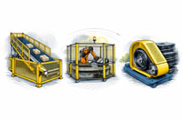
ndustrial machine guarding solutions showing a conveyor system, a robotic cell, and a belt drive with fixed guards designed to prevent access to hazardous moving parts.

Machine guarding examples showing a guarded conveyor, enclosed robotic cell, and belt drive with safety covers

3D LiDAR scanning and 3D modelling service button โ€” laser scanner capturing a point cloud for engineering and CAD modelling
Mechanical engineering services

Machine guarding remains one of the most persistent and preventable safety risks across Australian industry.
Despite improvements in automation, safety culture, and regulatory oversight, serious injuries and fatalities involving machinery continue to occur every year, particularly in manufacturing, mining, food processing, and materials handling.

Over the past decade, regulators, courts, and insurers have consistently reinforced one message:
machine guarding is not optional, not administrative, and not a โ€œfit-laterโ€ activity โ€” it is a core engineering and governance responsibility.

This article examines:

  • The international and Australian standards framework for machine guarding
  • Accident and injury trends over the past ten years
  • Legal and enforcement signals emerging from prosecutions
  • Why machine guarding must be treated as a strategic asset-risk issue, not just a safety task

The Global Framework: International Standards for Machine Guarding

Machine guarding is governed globally through standards developed by the International Organization for Standardization (ISO).


ISO standards portal
Core International Standards

ISO 12100 Risk assessment

ISO 14120 Guard design

ISO 13857 Safety distances

ISO 13849-1 Interlocks & control systems

These standards establish a risk-based engineering approach, requiring hazards to be:

  1. Identified
  2. Eliminated where possible
  3. Engineered out through guards and control systems
  4. Verified through geometry, distances, and fail-safe logic

This methodology underpins CE marking, global OEM compliance, and multinational EPC project delivery.


The Australian Context: AS 4024 and WHS Expectations

Australia adopts and localises ISO principles through AS 4024 โ€“ Safety of Machinery, referenced extensively by regulators under Work Health and Safety (WHS) legislation.

Standards Australia โ€“ AS 4024 Series
Key Australian Standards

AS 4024.1201 Risk assessment

AS 4024.1601 Guards

AS 4024.1602 Interlocks

AS 4024.1801 Safety distances

AS 4024.1501 Safety control systems

While standards themselves are not legislation, courts and regulators consistently use AS 4024 as the benchmark for determining whether risks have been managed so far as is reasonably practicable.


Australia does not publish a dedicated โ€œmachine guarding accidentโ€ metric. However, national data from Safe Work Australia clearly shows machinery remains a leading cause of serious harm.

Safe Work Australia โ€“ Key WHS statistics:
National Trends (Approximate โ€“ Last 10 Years)

MetricEvidence Source
~1,850+ traumatic work fatalitiesSafework Australia
~180โ€“200 fatalities per yearSafework Australia
Highest fatality rateMachinery operators & drivers
~130,000โ€“140,000 serious injury claims annuallyAustralian Institute of health and welfare
Common mechanismsTrapped by machinery, struck by moving objects

Machinery operators consistently record:

  • The highest fatality rates of all occupation groups
  • Disproportionate representation in serious injury claims
  • Higher exposure to entanglement, crush, shear, and impact hazards

These mechanisms are directly linked to guarding effectiveness, not worker behaviour alone.


What Hasnโ€™t Changed โ€” and Why It Matters

1. Legacy Plant Remains a Key Risk

Many incidents involve:

  • Older machinery
  • Brownfield modifications
  • Equipment altered without re-engineering guarding

Australian WHS law does not grandfather unsafe plant.


2. Guarding Is Still Added Too Late

Common failures include:

  • Guards designed post-fabrication
  • Inadequate reach distances
  • Interlocks added without validated performance levels

This often leads to bypassing, removal, or unsafe maintenance practices.


3. Lack of Engineering Documentation

Post-incident investigations frequently identify:

  • No formal risk assessment
  • No justification against AS 4024 or ISO standards
  • No evidence that guarding was engineered, tested, or validated

In legal proceedings, absence of documentation is treated as absence of control.


Australian regulators (WorkSafe NSW, WorkSafe VIC, SafeWork QLD, SafeWork SA) have consistently prosecuted machine-guarding failures, particularly where:

  • Hazards were known
  • Improvement notices were ignored
  • Guards were removed or ineffective

Regulator portals:

Courts have reinforced that:

  • Training does not replace guarding
  • PPE does not replace guarding
  • Signage does not replace guarding

Guarding as a Governance Issue

For executives and boards, machine guarding intersects with:

  • Officer due diligence obligations
  • Asset lifecycle risk
  • Insurance and liability exposure
  • Business continuity and ESG performance

Well-designed guarding:

  • Reduces downtime
  • Enables safer automation
  • Improves workforce confidence
  • Creates defensible compliance positions

The Engineering Reality: Geometry Drives Compliance

Modern compliance relies on:

  • Verified reach distances
  • Measured openings and clearances
  • Validated interlock logic

This is why accurate:

  • As-built capture
  • 3D modelling
  • Engineering-grade spatial data

are increasingly essential for brownfield and high-risk plant.


Looking Ahead: The Next Decade

Trends indicate:

  • Greater scrutiny of legacy machinery
  • Stronger linkage between standards and prosecutions
  • Higher expectations for engineering evidence
  • Increased use of digital engineering to prove compliance

Organisations that integrate guarding early into engineering workflows will be better protected legally, operationally, and reputationally.


Hamilton By Design logo displayed on a blue tilted rectangle with a grey gradient background

Final Thought

Machine guarding is not about mesh and fences.
It is about engineering intent, risk ownership, and accountability.

The last decade of Australian data, prosecutions, and standards alignment is clear:
when guarding fails, the outcomes are predictable โ€” and preventable.

Structural drafting services button
3D LiDAR scanning and 3D modelling services button
Mechanical drafting services button

Our clients:

Name
Would you like us to arrange a phone consultation for you?
Address

#Machine guarding standards Australia #Machinery safety best practices #AS/NZS 4024 machine guarding #Workplace safety machinery #Industrial safety compliance #Machine guarding lessons for engineers
Finite Element Analysis (FEA) engineering simulation button
Mechanical engineering services

Lessons from a Landmark Case:

The Importance of Robust Structural Design Review

In 2024, SafeWork SA concluded a landmark case involving a spectator-roof collapse during a football club redevelopment project in South Australia. While no life-threatening injuries occurred, the incident highlighted how critical it is for design, review, and certification processes to work together to ensure safety on site.

This was the first successful design-related prosecution under South Australiaโ€™s Work Health and Safety Act, sending a clear signal to the engineering and construction sector: design decisions carry legal and safety obligations, not just technical ones.

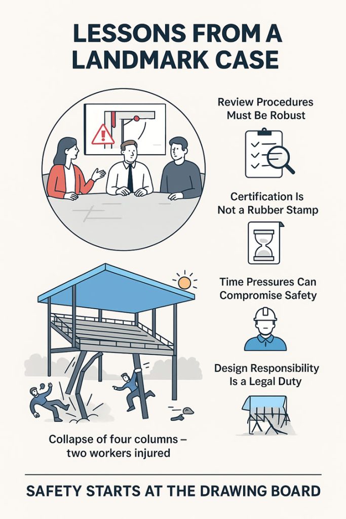
Infographic titled โ€œLessons from a Landmark Case,โ€ showing engineers reviewing a design, icons highlighting robust review procedures, proper certification, time-pressure risks, and legal design responsibilities. The lower illustration depicts a structure collapsing after four column failures with two workers falling, emphasising the message โ€œSafety starts at the drawing board

What Happened (Briefly)

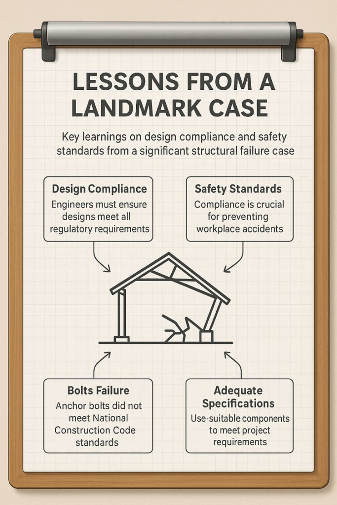
During roof sheeting works in late 2021, four of seven supporting columns of a cantilevered spectator roof failed, causing two apprentices to slide down the roof sheets. SafeWork SAโ€™s investigation found that the anchor bolts specified for the column base plates were inadequate and did not meet the requirements of the National Construction Code (NCC).

An independent compliance review also failed to detect this issue, allowing the error to pass unchecked into construction. The result was a collapse that could have had far more severe consequences had the roof been fully loaded or occupied.

Key Learnings for the Industry

This case underscores several important lessons for engineers, designers, project managers, and certifiers:

1. Design Responsibility Is a WHS Duty

Under the WHS Act, designers have a duty to ensure their work is safe not just in its intended use, but during construction. This means bolts, connections, and base plates must be designed for real-world loads โ€” including wind uplift, combined shear and tension, and concrete breakout limits per NCC and relevant Australian Standards.

2. Review Procedures Must Be Robust โ€” and Followed

Having a documented review procedure is not enough if it isnโ€™t rigorously applied. Independent verification and internal peer review are critical to catching design errors before they reach site.

3. Certification Is Not a Rubber Stamp

Independent certifiers play a key role in safeguarding public safety. They must actively verify that designs meet compliance, rather than simply sign off on documentation.

4. Time Pressures Can Compromise Safety

Compressed project timelines were noted as a factor in missed opportunities to catch the error. Project teams must resist the temptation to shortcut review steps when schedules are tight โ€” safety must remain non-negotiable.

5. Documentation & Traceability Protect Everyone

Maintaining calculation records, checklists, and review signoffs creates a clear audit trail. This helps demonstrate due diligence if something goes wrong.

Infographic titled โ€˜Lessons From a Landmark Caseโ€™ displayed on a clipboard. It highlights key learnings from a structural failure case: design compliance, safety standards, bolts failure, and adequate specifications. At the centre is a simple line drawing of a collapsed structure, with arrows pointing to four labelled boxes describing the importance of regulatory compliance, workplace safety standards, anchor bolt failures, and using suitable components to meet project requirements

Why This Matters

The collapse at Angaston Football Club was a relatively small incident with minor injuries โ€” but it could easily have been catastrophic. By learning from cases like this, the industry can improve its processes and prevent future failures.

As professionals, our role is to design for safety, verify rigorously, and document clearly. Doing so protects workers, end-users, and our own organisations.

Legal & Ethical Considerations

This post is intended as a learning resource, not as an allocation of blame. The case referenced is a matter of public record through SafeWork SA and SAET decisions, and all commentary here focuses on general principles of safe design and compliance.

We recommend that other practitioners review their own QA and certification procedures in light of this case to ensure compliance with the National Construction Code and WHS obligations.

More Information —> The Advertiser / Adelaide Now

Hamilton By Design logo displayed on a blue tilted rectangle with a grey gradient background

Mechanical Engineering | Structural Engineering

Mechanical Drafting | Structural Drafting

3D CAD Modelling | 3D Scanning

Chute Design

SolidWorks Contractors in Australia

Hamilton By Design โ€“ Blog

Finite Element Analysis (FEA) engineering simulation button
Mechanical engineering services

Designing for Developing Hazards

Designing for Developing Hazards: Lessons from the Derrimut Crane Collapse

Crane accidents are among the most visible reminders of the risks inherent in construction. The collapse of a crane at a data centre site in Derrimut, Melbourne, brought attention once again to the vulnerability of temporary lifting structures. While formal investigations are still underway, and no conclusions should be drawn prematurely, the event provides a valuable opportunity for reflection within the engineering community.

This article considers the collapse not as an isolated failure but as a case study in hazard identification. In particular, it highlights how mechanical engineers must adapt from a static, design-phase view of risk to a dynamic, real-time approach to hazard monitoring. Wind, soil stability, and load conditions are well-known hazards. But with modern tools โ€” including LiDAR scanning for obstacle detection โ€” engineers can move toward a future where developing hazards are continuously tracked, anticipated, and controlled.


Illustrated infographic titled โ€œDesigning for Developing Hazards,โ€ showing a mechanical engineer at a computer analysing a structure while surrounded by icons representing hazard identification. Elements include rain and storm clouds, a lightbulb symbolising ideas, AI tools, a wind sensor for wind monitoring, and a soil test graphic for soil analysis. Arrows connect these hazards to a mobile crane lifting equipment, alongside an alarm system alerting operators. The layout highlights how engineers assess weather, wind, soil conditions, and digital data to design safely around evolving hazards.
3D LiDAR scanning and 3D modelling service button โ€” laser scanner capturing a point cloud for engineering and CAD modelling
Mechanical engineering services

From Hazard Identification to Live Hazard Monitoring

Hazard identification has traditionally been a design-phase process: engineers anticipate risks, apply safety factors, and create conservative margins. This remains essential. Yet the Derrimut collapse illustrates the limits of a static model in a dynamic environment.

Cranes are exposed to evolving hazards:

  • Wind gusts that change minute by minute.
  • Soil stability that shifts with rainfall, excavation, or groundwater.
  • Obstacles such as power lines or nearby structures, which can create cascading risks if struck.
  • Load dynamics, including swinging or sudden movement.

What is needed is a transition from hazard identification to hazard monitoring: a continuous loop where design assumptions are validated against real-time data, and where developing risks are detected before they become failures.


Wind Hazards: Predicting the Unpredictable

Wind is a leading cause of crane collapses. Engineers know the mathematics: pressure rises with the square of velocity. A 50 km/h gust exerts twice the force of a 35 km/h breeze.

Most cranes today are fitted with anemometers and alarms, but these are often basic: a single reading at a single point, with alarms sounding when preset thresholds are exceeded. This approach can miss:

  • Local gust variability along a long jib.
  • Interaction with crane orientation (wind hitting the broadside is more critical than aligned wind).
  • Forecasted conditions that could deteriorate within minutes.

Next-generation wind monitoring could include:

  • Multi-point sensor arrays on cranes.
  • Integration with Bureau of Meteorology gust forecasts.
  • AI models predicting when risk thresholds will be exceeded, not just reporting when they are crossed.
  • Automatic crane repositioning to minimise wind exposure.

This transforms alarms from reactive to predictive โ€” the difference between warning after a hazard is present and anticipating before it materialises.


Soil Hazards: Stability Under Load

Ground conditions are another silent but critical hazard. Outriggers may impose hundreds of kilonewtons on pads, meaning even small soil weaknesses can lead to tilting or overturning.

Engineering practice already includes soil investigations: boreholes, CPT, SPT, and FEA models. But these tests capture conditions before installation, not necessarily during operation. Soil strength can change due to rainfall, groundwater shifts, or nearby excavation.

Live soil monitoring can be achieved with:

  • Load cells under mats to track ground reactions.
  • Settlement gauges to detect tilt.
  • Piezometers for pore pressure during rain events.
  • Integrated warnings when ground resistance trends downward.

This approach acknowledges soil as a living hazard that changes daily.


LiDAR and Obstacle Detection: Power Lines and Proximity Hazards

One striking feature of the Derrimut collapse was the craneโ€™s boom striking power lines. Contact with utilities is a recurrent hazard in crane operations worldwide. While operators are trained to maintain exclusion zones, in practice visibility, fatigue, or unexpected boom movement can still lead to contact.

LiDAR scanning offers a solution.

  • How it works: LiDAR (Light Detection and Ranging) emits laser pulses to map surroundings in 3D with centimetre accuracy. Mounted on a crane, it can create a live digital map of nearby obstacles.
  • Application in cranes:
    • Detecting and mapping power lines, buildings, or scaffolding in the lift path.
    • Setting proximity alarms when a boom, hook, or load approaches a defined clearance.
    • Combining with wind data to predict if gusts could push the load into restricted zones.

In aviation, LiDAR and radar-based systems are standard for obstacle detection. In construction, adoption is patchy. Yet the technology exists, is cost-effective, and could dramatically reduce risks of contact with hazards like live power lines.

LiDARโ€™s strength lies not only in static mapping but in detecting movement โ€” for example, when a suspended load begins to swing toward a power line due to a gust. This is a quintessential developing hazard, one that static design could never fully capture.


Integrated Hazard Dashboards

Wind, soil, and LiDAR obstacle detection all provide valuable data. But their true power lies in integration. Imagine a crane operatorโ€™s cabin equipped with a single dashboard displaying:

  • Wind speeds and gust forecasts, colour-coded for risk.
  • Soil reaction forces under each outrigger, with alerts if settlement is trending.
  • LiDAR mapping of nearby structures and power lines, with real-time clearance zones.
  • Predictive risk models showing probability of instability or contact over the next 30 minutes.

This integration mirrors aviationโ€™s cockpit: multiple inputs fused into actionable guidance. For cranes, such systems could shift the operatorโ€™s role from reactive decision-maker to proactive risk manager.


AI as a Predictive Partner

Artificial Intelligence has a natural role in hazard monitoring:

  • Sensor fusion: combining wind, soil, and LiDAR inputs into coherent risk profiles.
  • Prediction: learning from past crane incidents to forecast when risks are likely to escalate.
  • Decision support: providing operators with clear options (โ€œsafe to continue lift for 20 minutesโ€ / โ€œhalt operations โ€” clearance margin < 1mโ€).

The challenge is balance. AI should not replace human oversight, but augment it. Over-reliance could create new vulnerabilities if operators become complacent. The design challenge is to build AI into systems that support human judgment rather than substitute for it.


Ethics and Engineering Responsibility

The Derrimut collapse underscores the ethical responsibility of mechanical engineers. Hazard identification is not just a design requirement; it is a matter of public safety. The profession has a duty to anticipate, detect, and control risks wherever possible.

The tools now exist to monitor developing hazards โ€” wind sensors, soil gauges, LiDAR scanners, and AI dashboards. If lives and infrastructure can be protected through wider adoption of these tools, then the question becomes one of responsibility: should they be optional, or mandatory?


Open Questions for the Future

  1. Would integrated live monitoring have reduced the risks at Derrimut?
  2. Should all cranes be fitted with LiDAR obstacle detection as standard?
  3. Do we already have enough technology, but lack regulation and enforcement?
  4. What role should AI play in balancing predictive insight with operator autonomy?

Conclusion

The Derrimut incident remains under investigation. No conclusions can be drawn about its specific cause until findings are published. Yet as a case study, it illustrates the broader point that hazards in crane operations are dynamic. Wind, soil, obstacles, and loads evolve minute by minute.

Mechanical engineers have the tools โ€” wind sensors, soil monitors, LiDAR scanners, integrated dashboards, and AI โ€” to detect these developing hazards. The challenge is to move from a culture of static design assumptions to one of continuous hazard monitoring.

The ultimate professional question is this: If aviation can integrate multiple systems to monitor and predict hazards, why canโ€™t construction do the same for cranes? And if we can, how soon will we accept the ethical responsibility to make it standard?


Hamilton By Design logo displayed on a blue tilted rectangle with a grey gradient background

References and Further Reading

  • ISO 4301 / AS 1418 โ€” Crane standards covering stability and wind.
  • ISO 12480-1:2003 โ€” Safe use of cranes; includes environmental hazard monitoring.
  • WorkSafe Victoria Guidance Notes โ€” Crane safety management.
  • Holickรฝ & Retief (2017) โ€” Probabilistic treatment of wind action in structural design.
  • Nguyen et al. (2020) โ€” Real-time monitoring of crane foundation response under variable soil conditions.
  • Liebherr LICCON โ€” Example of integrated load and geometry monitoring.
  • FAA LLWAS โ€” Aviationโ€™s real-time wind shear alert system, model for construction.
  • Recent research in LiDAR obstacle detection (e.g., IEEE Transactions on Intelligent Transportation Systems) โ€” showing LiDARโ€™s potential in complex environments.

Mechanical Engineering

Consulting Engineers

Our clients:

Name
Would you like us to arrange a phone consultation for you?
Address
Finite Element Analysis (FEA) engineering simulation button
Mechanical engineering services

Maximising Uptime at Transfer Points: How Hamilton By Design Optimises Chutes, Hoppers, and Conveyors for the Mining Industry

In the mining industry, system uptime isnโ€™t just a goalโ€”itโ€™s a necessity. Transfer points such as chutes, hoppers, and conveyors are often the most failure-prone components in processing plants, especially in high-wear environments like HPGR (High Pressure Grinding Rolls) circuits. Abrasive ores, heavy impact, fines accumulation, and moisture can all combine to reduce flow efficiency, damage components, and drive up maintenance costs.

At Hamilton By Design, we help mining clients minimise downtime and extend the life of their material handling systems by applying advanced 3D scanning, DEM simulation, smart material selection, and modular design strategies. This ensures that transfer points operate at peak efficiencyโ€”day in, day out.

Hereโ€™s how we do it:

Optimised Flow with DEM-Based Chute & Hopper Design

Flow blockages and misaligned velocities are among the biggest contributors to transfer point failure in the mining industry. Thatโ€™s why we use Discrete Element Method (DEM) simulations to model bulk material flow through chutes, hoppers, and transfer transitions.

Through DEM, we can simulate how different oresโ€”ranging from dry coarse rock to sticky finesโ€”move, compact, and impact structures. This allows us to tailor chute geometry, outlet angles, and flow paths in advance, helping:

  • Prevent material buildup or arching inside hoppers and chutes
  • Align material velocity with the conveyor belt speed using hood & spoon or trumpet-shaped designs
  • Reduce wear by managing trajectory and impact points

Optimised flow equals fewer shutdowns, longer equipment life, and better plant throughput.

Wear-Resistant Liners & Material Engineering

Not all wear is the sameโ€”and neither are the materials we use to combat it. By studying the abrasion and impact zones in your chute and hopper systems, we strategically apply wear liners suited to each application.

Our engineering team selects from:

  • AR (Abrasion-Resistant) steels for high-wear areas
  • Ceramic liners in fines-rich or ultra-abrasive streams
  • Rubber liners to absorb shock and reduce noise

This approach reduces liner replacement frequency, improves operational safety, and lowers the risk of unplanned shutdowns at key transfer points.

Dust and Spillage Control: Cleaner, Safer Operation

Dust and spillage around conveyors and transfer chutes can lead to extensive cleanup time, increased maintenance, and health hazards. At Hamilton By Design, we treat this as a core design challenge.

We design chutes and hoppers with:

  • Tight flange seals at interface points
  • Enclosed transitions that contain dust at the source
  • Controlled discharge points to reduce turbulent material drops

This reduces environmental risk and contributes to more consistent plant performanceโ€”especially in confined or enclosed processing facilities in the mining industry.

Modular & Accessible Designs for Faster Maintenance

When liners or components need replacement, every minute counts. That’s why our chute and hopper systems are built with modular sectionsโ€”each engineered for fast removal and reinstallation.

Key maintenance-driven design features include:

  • Bolt-on panels or slide-in liner segments
  • Accessible inspection doors for safe visual checks
  • Lightweight modular components for easy handling

These details reduce labour time, enhance safety, and keep your plant online longerโ€”especially critical in HPGR zones where throughput is non-stop.

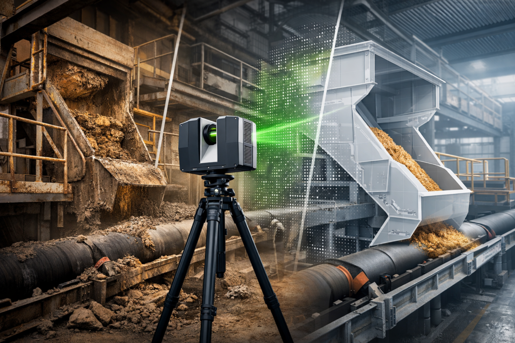
3D laser scanner capturing a blocked mining transfer chute with a digital redesign overlay above a conveyor.
3D LiDAR scanning and 3D modelling service button โ€” laser scanner capturing a point cloud for engineering and CAD modelling
Mechanical engineering services

Precision 3D Scanning & 3D Modelling for Retrofit Accuracy

One of the most powerful tools we use is 3D scanning. In retrofit or brownfield projects, physical measurements can be inaccurate or outdated. We solve this by conducting detailed laser scans that generate accurate point cloud dataโ€”a precise digital twin of your plant environment.

That data is then transformed into clean 3D CAD models, which we use to:

  • Design retrofits that precisely match existing structure
  • Identify interferences or fit-up clashes before fabrication
  • Reduce install time by ensuring right-first-time fits

This scan-to-CAD workflow dramatically reduces rework and error margins during installation, saving time and cost during shutdown windows.

Real-World Application: HPGR & Minerals Transfer Systems

In HPGR-based circuits, transfer points between crushers, screens, and conveyors experience high rates of wear, dust generation, and blockagesโ€”particularly where moisture-rich fines are present.

Hereโ€™s how Hamilton By Designโ€™s methodology addresses these pain points:

  • DEM-based flow modelling ensures the HPGR discharge flows cleanly into chutes and onto conveyors without buildup.
  • Hood/spoon geometries help track material to belt velocityโ€”minimising belt wear and reducing misalignment.
  • Strategic liner selection extends life in critical wear zones under extreme abrasion.
  • Modular chute designs allow for fast liner swap-outs without major disassembly.
  • 3D scanning & CAD design ensures new chute sections fit seamlessly into existing HPGR and conveyor frameworks.

By designing smarter transfer systems with these technologies, we enable operators to reduce downtime, increase liner life, and protect critical assets in high-throughput mining applications.

Uptime Benefits at a Glance

Performance AreaImpact on Mining Operations
Smooth bulk material flowFewer clogs, improved throughput, longer operating cycles
Velocity-matched dischargeLower conveyor belt wear and downtime
Robust wear protectionLonger life, fewer liner replacements
Modular designFaster maintenance turnarounds during scheduled shutdowns
3D scanning & CAD integrationPrecise fit, reduced installation time, fewer errors during retrofit

Final Word: Engineering That Keeps the Mining Industry Moving

At Hamilton By Design, we combine mechanical engineering expertise with 3D modelling, material flow simulation, and smart fabrication practices to deliver high-performance chute, hopper, and transfer point systems tailored for the mining industry.

Whether youโ€™re dealing with a problematic HPGR discharge, spillage issues, or planning a brownfield upgrade, our integrated design process delivers results that improve reliability, extend service life, and protect uptime where it matters most.

Looking to retrofit or upgrade transfer systems at your site?
Letโ€™s talk. We bring together 3D scanning, DEM modelling, practical engineering, and proven reliability to deliver systems that workโ€”from concept through to install.

Our clients

Reach out

Name
Would you like us to arrange a phone consultation for you?
Address
Hamilton By Design logo displayed on a blue tilted rectangle with a grey gradient background

#3DScanning #MiningIndustry #Chutes #Hoppers #TransferPoints #3DModelling #MechanicalEngineering #HPGR #PlantUptime #HamiltonByDesign

Structural Drafting | Mechanical Drafting | 3D Laser Scanning

Mechanical Engineering

3D CAD Modelling Australia service banner for Hamilton By Design
Australian Drafting logo featuring bold white text reading "Australian Drafting" centred on a blue rounded rectangle background.
Engineering Governance title graphic featuring bold white text reading "Engineering Governance" centred on a blue rounded rectangle background.
Mechanical, Structural & Pipework Drafting service banner by Hamilton By Design featuring white text on a blue background.
Mechanical engineering services
Blue rounded button with the text โ€œSolidWorks Designโ€ in white.
Finite Element Analysis (FEA) engineering simulation button
3D LiDAR Scanning Darwin for engineering surveys, laser scanning, reality capture and point cloud modelling services
3D LiDAR Scanning Australia engineering services for laser scanning, reality capture, scan-to-CAD, Scan-to-BIM and as-built documentation across Australia
3D LiDAR scanning services on the Central Coast providing engineering-grade laser scanning, point cloud capture, scan-to-CAD modelling and industrial reality capture for infrastructure and industrial projects.
3D LiDAR Scanning Perth for engineering surveys, laser scanning, reality capture and point cloud modelling services
3D LiDAR Scanning Sydney for engineering surveys, laser scanning, reality capture and point cloud modelling services
3D LiDAR Scanning Brisbane for engineering surveys, laser scanning, reality capture and point cloud modelling services
3D LiDAR Scanning Canberra for engineering surveys, laser scanning, reality capture and point cloud modelling services
3D LiDAR Scanning Newcastle for engineering surveys, laser scanning, reality capture and point cloud modelling services
3D LiDAR Scanning Adelaide for engineering surveys, laser scanning, reality capture and point cloud modelling services